Tabla de contenido
Publicidad
Idiomas disponibles
Idiomas disponibles
Enlaces rápidos
Publicidad
Tabla de contenido

Manuales relacionados para KTM 69034081044


Resumen de contenidos para KTM 69034081044
- Página 1 Information Power Parts 69034081044 03. 2009 3.211.443 *3211443* www.ktm.com...
- Página 2 KTM Power Parts are race proven to offer the ultimate in performance. KTM WILL NOT BE HELD LIABLE FOR IMPROPER INSTALLATION OR USE OF THIS PRODUCT. Please follow all instructions provided. If you are unsure of any installation procedure, please contact a certified KTM dealer.
- Página 3 1x Kabelband 300/4.8mm (8) 44011076305 1x Kabel2 (12) 69034081030 Vorarbeiten - Motorrad aufbocken. HINWEIS:Es wird eine bei KTM erhältliche Hinterradhebevorrichtung (610.29.055.400) mit dem Universal V-Adapter (610.29.055.120) emp- fohlen. - Sitz demontieren. - Tank demontieren. - Kühlerverkleidung links und rechts demontieren.
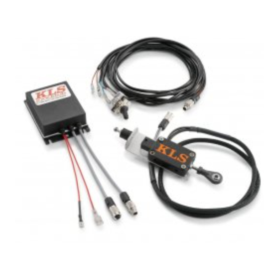
- Página 4 Lieferumfang Schaltautomat 69034080000 1x Sensorbox (1) 1x Schaltautomat (2) 1x Kabel1 (3) 1x EIN/AUS Schalter (5) 1x Inbusschlüssel (6) Mutter (7) und (11) von Sensorbox (1) demontieren. Mutter (7) dient zum Kontern der Mutter (11). Sensorbox an Position (A) mit der Mutter (11) befestigen. Mit der Mutter (7) kontern.
- Página 5 - Schaltautomat am Heck mit den Kabelbindern (Lieferumfang Montagekit) befestigen. HINWEIS: Der Schaltautomat kann aus Platzgründen nicht in Verbindung mit der optio- nal erhätlichen Alarmanlage verwendet werden. Kabel1 am Schaltautomaten anstecken. Kabel1, wie in Skizze gezeigt, nach vorne verlegen. HINWEIS: Kabel1 durch die Führung nach vorne verlegen (Bild A).
- Página 6 - Original Schraube (1) entfernen. - Halteblech für EIN/AUS Schalter (2) positionieren und mit der im Lieferumfang enthaltenen Schraube M6x20 (1) montieren. - EIN/AUS Schalter am Halteblech montieren und Stecker des Kabel1 am Schalter anstecken (Bild A). HINWEIS: Nach erfolgter Montage aller Kabel kontrollieren, ob die Stecker am Schalter richtig positioniert sind.
- Página 7 GRUNDEINSTELLUNG Einstellen der Schaltpunkte an der Sensorbox HINWEIS: Die Lage der Schaltpunkte hängt von der Schalt- und Getriebemechanik des Motors selbst, sowie von der Dynamik des Schaltvorganges ab und kann ggf. im Fahrbetrieb weiter optimiert werden. Eine optimale Einstellung ist dann erreicht, wenn die Betätigung des Schalthebels nahezu ohne fühlbaren Widerstand schnell und vollständig möglich ist.
- Página 8 1x cable2 (12) 69034081030 Preparations - Jack up the motorcycle. NOTE: A rear wheel lifting device (610.29.055.400) available from KTM with the universal V-adapter (610.29.055.120) is recommended. - Remove the seat. - Remove the tank. - Remove the left and right radiator shrouds.
- Página 9 Scope of delivery, quick shifter 69034080000 1x sensor box (1) 1x quick shifter (2) 1x cable1 (3) 1x ON/OFF switch (5) 1x Allen key (6) - Remove nuts (7) and (11) from sensor box (1). - Nut (7) locks nut (11). - Attach the sensor box at position (A) with nut (11).
- Página 10 - Attach the quick shifter to the rear with the cable ties (included in the assembly kit). NOTE: For space reasons, the quick shifter cannot be used together with the optional alarm system. - Connect Cable1 to the quick shifter. - Route Cable1 to the front as shown in the illustration.
- Página 11 - Remove original screw (1). - Position the retaining plate for ON/OFF switch (2) and mount it with screw M6x20 (1) included in the scope of supply. - Mount the ON/OFF switch on the retaining plate and plug the connector of Cable1 into the switch (Figure A).
-
Página 12: Basic Setting
BASIC SETTING Setting the shift points on the sensor box NOTE: The position of the shift points depends on the shift and gear mechanism of the engine itself, as well as on the dynamics of the shifting procedure and can be further optimized during operation, if necessary. The setting is optimal when the shift lever can be operated quickly and fully without a perceptible resistance. -
Página 13: Operazioni Preliminari
69034081030 Operazioni preliminari Porre la motocicletta sul cavalletto alzamoto. NOTA BENE: si consiglia di utilizzare il dispositivo di sollevamento ruota posteriore (610.29.055.400, disponibile presso KTM) con l'adattatore universale a V (610.29.055.120). - Smontare la sella. - Smontare il serbatoio. - Smontare la copertura del radiatore a sinistra e a destra. - Página 14 Volume della fornitura del dispositivo di cambio marce automatico 69034080000 N. 1 scatola sensori (1) N. 1 dispositivo di cambio marce automatico (2) N. 1 cavo1 (3) N. 1 interruttore ON/OFF (5) N. 1 chiave a brugola (6) - Smontare i dadi (7) e (11) della scatola sensori (1). - Il dado (7) serve a serrare il dado (11).
- Página 15 - Fissare posteriormente il dispositivo di cambio marce automatico utiliz- zando le fascette serracavi (in dotazione al kit di montaggio). NOTA BENE: Per motivi di spazio, il dispositivo di cambio marce automatico non può essere utilizzato insieme all'impianto d'allarme opzionale. - Collegare il cavo1 al dispositivo di cambio marce automatico.
- Página 16 - Rimuovere la vite originale (1). - Posizionare la piastrina dell'interruttore ON/OFF (2) e montarla con la vite M6x20 (1) fornita in dotazione. - Montare l'interruttore ON/OFF sulla piastrina e collegare il connettore del cavo1 all'interruttore (figura A). NOTA BENE: Terminato il montaggio, controllare tutti i cavi e verificare che i connettori risultino posizionati correttamente sull'interruttore.
- Página 17 TARATURA BASE Regolazione dei punti d'innesto sulla scatola sensori NOTA BENE: La posizione dei punti d'innesto dipende dalla meccanica di innesto e del cambio del motore, nonché dalle dinamiche di cambiata e, se necessario, può essere ottimizzata durante la marcia. La regolazione ottimale è quella in cui si riesce ad azionare la leva del cambio, in modo rapido e fino in fondo, senza percepire quasi alcuna resistenza.
- Página 18 69034081030 Travaux préalables Béquiller la moto. REMARQUE : Une béquille arrière (610.29.055.400) et un adaptateur en V universel (610.29.055.120) disponibles auprès de KTM sont recom- mandés. - Déposer la selle. - Déposer le réservoir. - Démonter le cache du radiateur à droite et à gauche.
- Página 19 Contenu de la livraison automate 69034080000 1x Boîtier de capteurs(1) 1x Automate (2) 1x Câble1 (3) 1x Bouton MARCHE/ARRÊT (5) 1x Clé Allen (6) - Retirer les écrous (7) et (11) sur le boîtier de capteurs (1). - L'écrou (7) permet de contrer l'écrou (11). - Fixer le boîtier de capteurs en position (A) avec l'écrou (11).
- Página 20 - Fixer l'automate à l'arrière avec des serre-câble (contenu de la livraison kit de montage). REMARQUE : Par manque de place, l'automate ne peut pas être utilisé en conjonction avec l'alarme disponible en option. - Brancher le câble1 sur l'automate. - Disposer le câble1 vers l'avant, comme sur la photo.
- Página 21 - Retirer la vis d'origine (1). - Placer la tôle de fixation du bouton MARCHE/ARRÊT (2) et la fixer avec la vis M6x20 (1) fournie dans le contenu de la livraison. - Monter le bouton MARCHE/ARRÊT sur la tôle de fixation et brancher le connecteur du câble1 sur le bouton (fig.
-
Página 22: Réglage De Base
RÉGLAGE DE BASE Réglage des points de passage sur le boîtier de capteurs REMARQUE : La position des points de passage dépend de la boîte de vitesses et de la mécanique du moteur, ainsi que de la dynamique de l'opération de passage, et peut le cas échéant être optimisé pendant les trajets. Un réglage optimal est atteint lorsque le sélecteur peut être actionné... -
Página 23: Trabajos Previos
Trabajos previos Levantar la motocicleta sobre un soporte. NOTA: Se recomienda utilizar el dispositivo elevador para la rueda trasera (610.29.055.400) que puede adquirirse de KTM junto con el adaptador universal en V (610.29.055.120). - Desmontar el asiento. - Desmontar el depósito. - Página 24 Volumen de suministro del cambio automático 69034080000 1x Caja de sensores (1) 1x Cambio automático (2) 1x Cable 1 (3) 1x Interruptor de conexión y desconexión (5) 1x Llave Allen (6) - Desmontar las tuercas (7) y (11) de la caja de sensores (1). - La tuerca (7) permite asegurar la tuerca (11).
- Página 25 - Fijar el cambio automático a la parte trasera con las cintas sujetacables (volumen de suministro del kit de montaje). NOTA: Por motivos de espacio, el cambio automático y el sistema de alarma opcional no se pueden utilizar juntos. - Conectar el cable 1 al cambio automático. - Llevar el cable 1 hacia delante tal como se muestra en el esquema.
- Página 26 - Quitar el tornillo original (1). - Colocar el interruptor de conexión y desconexión (2) y montarlo con el tornillo M6x20 (1) incluido en el volumen de suministro. - Montar el interruptor de conexión y desconexión en la chapa de sujeción y conectar el conector del cable 1 al interruptor (figura A).
-
Página 27: Ajuste Básico
AJUSTE BÁSICO Ajustar los puntos de cambio en la caja de sensores NOTA: La posición de los puntos de conexión depende del sistema mecánico del cambio y los engranajes del motor y de la dinámica del cambio de marchas y, de ser necesario, se puede optimizar en la marcha. El ajuste óptimo se alcanza cuando el accionamiento del pedal del cambio se realiza rápidamente, completamente y sin resistencia.