Publicidad
Enlaces rápidos
Consejo para un correcto montaje del kit: No apretar los tornillos del todo hasta asegurarse que el KIT está correctamente colocado y alineado.
Advice for correct fitting of the kit: Do not fully tighten the screws until it is ensured that the KIT is correctly attached and aligned.
Conseil pour un montage correct du kit: Ne pas serrer les vis avant de vous être assuré que le KIT est placé et aligné correctement.
Hinweis für einen korrekten Einbau des Bausatzes: Ziehen Sie die Schrauben nicht ganz fest, bevor Sie sich nicht vergewissert haben, daß der
Bausatz korrekt eingestellt und ausgerichtet ist.
Consiglio per un montaggio corretto del kit: Non stringere del tutto le viti fin tanto non si è sicuri che il kit è collocato correttamente e
allineato.
1.
C
2.
3.
C
Ø 21
Ø 21
Desmontar la tapeta (A) del transportin trasero (B),
mediante los tornillos (C).
Strip the lid (A) of the back carrier (B) down with
the screws (C).
Démonter le chapeau (A) du siège arrière (B), avec
A
les vis (C).
Abdeckung (A) des hinteren Platzes (B), durch
Lösen der Schrauben (C) abheben.
Smontare la copertura (A) del sedile aggiunto
posteriore (B), tramite le viti (C).
B
Por la parte interior de la tapeta (A) encontraremos
cuatro marcas, realizaremos un agujero Ø21 en las
marcas inferiores de la tapeta (A). Una vez realizados
los primeros agujeros, colocaremos la plantilla incluida
en este KIT TOP y realizaremos los dos agujeros
superiores que nos marcan a un Ø21. (Nota: aconse-
jamos que se realicen varios agujeros de Ø inferior
hasta llegar al Ø21, por seguridad del usuario).
On the inside part of the lid (A), four marks can be
found. Pierce them on a Ø21 in the marks you can
find in the lower part of the lid (A). Once the first
holes are done, place the grid included in KIT TOP
and pierce twice in the upper marks with a Ø21.
(WARNING: we advise you not to make the hole
directly at Ø21, it is better to start with a small hole
and make it broader later on).
Dans la partie interne du chapeau (A) nous trouvons
quatre marques, nous ferons un trou Ø21 sur les
marques inférieures du chapeau (A). Une fois les
premiers trous faits, nous placerons le gabarit inclus
dans ce KIT TOP et nous ferons les deux trous
supérieurs marqués à un Ø21. (Remarque: nous
recommandons de réaliser plusieurs trous de Ø
inférieur jusqu'à arriver au Ø21, pour que l'usager soit
en toute sécurité).
Im Inneren der Abdeckung (A) finden Sie vier Zeichen, wir
bohren ein Loch Ø21 an den unten angezeichneten
Punkten der Abdeckung (A). Nach dem Bohren der ersten
Löcher legen Sie die in diesem KIT TOP befindliche
Schablone auf und bohren die oben angezeichneten
Löcher mit Ø21. (Anmerkung: wir empfehlen Ihnen, aus
Sicherheitsgründen zunächst mehrere Löcher mit kleine-
rem Ø zu bohren, um dann genau Ø21 zu erreichen).
Per la parte interiore della copertura (A) trovaremo
quattro segni, realizzaremo un buco Ø21 nei segni
inferiori della copertura (A). Una volta realizzati i
primi buchi, collocaremo il modello incluso in questo
3
KIT TOP e realizzaremo i due buchi superiori che ci
portano a un Ø21. (Nota: consigliamo di realizzare
diversi buchi di Ø inferiore fin'arrivare al Ø21, per
sicurezza dell'usuario).
Colocar la tapeta (A) en el transportin trasero (B), mediante
2
los tornillos (C). Colocar los distanciadores (1).
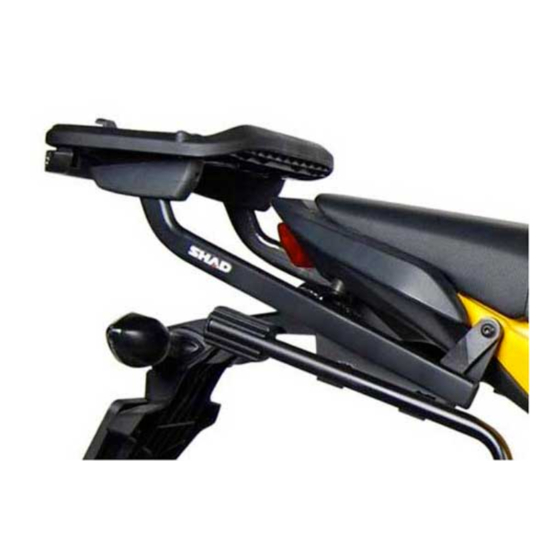
Montar el soporte KIT TOP (2), mediante los tornillos (3),
arandelas (4) y tuercas (5).
Place the lid (A) in the back carrier (B) with the screws (C).
1
Place the standoffs (1). Assemble the KIT TOP (2), with the
screws (C), rings (4) and nuts (5)
Placer le chapeau (A) sur le siège arrière (B), avec les vis
(C). Placer les entretoises (1). Monter le support KIT TOP
A
(2), avec les vis (3), les rondelles (4) et les écrous (5).
Abdeckung (A) auf dem hinteren Platz (B) mit Hilfe der
Schrauben (C) anbringen. Abstandhalter (1) anbringen.
B
Halterung TOP (2) mit Hilfe der Schrauben (3),
Unterlegscheiben (4) und Schraubenmuttern (5) befestigen.
4
Collocare la copertura (A) nel sedile aggiuto posteriore (B),
5
tramite le viti (C). Collocare i distanziatori (1).
Montare il supporto KIT TOP (2), tramite le viti (3), rondelle
(4) e bulloni (5).
Publicidad

Resumen de contenidos para Shad A0TL13ST
- Página 1 Consejo para un correcto montaje del kit: No apretar los tornillos del todo hasta asegurarse que el KIT está correctamente colocado y alineado. Advice for correct fitting of the kit: Do not fully tighten the screws until it is ensured that the KIT is correctly attached and aligned. Conseil pour un montage correct du kit: Ne pas serrer les vis avant de vous être assuré...
- Página 2 COMPONENTES / PARTS / COMPOSANTES / EINZELBAUTEILE / COMPONENTI: Pos. Ref. Cant. 260712 Distanciador Ø20 x Ø11 x 22 - Spacer - Entre-toise - Abstandshalter - Distanziatore 260880 KIT TOP 304152 Tornillo M6 x 50 DIN 7991 - Screw - Vis - Schraube - Vite 303017 Arandela esp Ø18 X Ø6 - Washer - Rondelle - Scheibe - Rondella Tuerca M6 autoblocante - Self-blocking Nut M6 - Écrou M6 autobloquant...


