Tabla de contenido
Publicidad
Idiomas disponibles
Idiomas disponibles
Enlaces rápidos
293 Wright St • Delavan, WI 53115
Phone: 800.937.6664
www.omnifilter.com
Tools and Fittings Required
•
Pencil
•
Utility knife (for plastic tubing)
•
Phillips screwdriver
•
Towel
•
Tape measure
•
Wall anchors
For sinks without extra hole for faucet
•
Hand or electric drill
•
Center punch
•
3/32-inch, 1/4-inch and 9/16-inch drill bits
•
File
Parts Included
•
Filter head assembly
•
Fittings kit
•
Lead free faucet kit
•
Cartridge life indicator
•
6 ft. of 1/4-inch plastic tubing
•
1500R filter cartridge, 1750R filter cartridge
•
Mounting screws and bracket
•
Inlet supply adapter
•
Teflon
®
tape
Optional Materials
•
Shut-off valve
•
Saddle tap valve with shut-off
The US2000 is tested and certified by WQA to NSF/
ANSI Standard 42 for the reduction of chlorine
taste and odor, and Particulate Class I and against
Standard 53 for the reduction of Cyst, Lead, Lindane,
Atrazine, Turbidity, Mercury, Asbestos, MTBE and
VOC.
For further operating, installation, maintenance,
parts or assistance:
Call OMNIFILTER Customer Service at:
800.937.6664
©2009 Pentair Residential Filtration, LLC
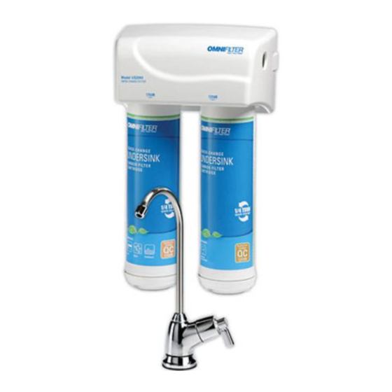
Model US2000
Quick-Change Filter System
INSTALLATION INSTRUCTIONS
English . . . . . . . . . . . . . . . . . . . . . . . . . . . . . . . . . . . . . Pages 2-9
Replacement Parts . . . . . . . . . . . . . . . . . . . . . . . . . . . . . .Page 7
Modelo US2000
Sistema de filtro de cambio rápido
INSTRUCCIONES DE INSTALACIÓN
Español . . . . . . . . . . . . . . . . . . . . . . . . . . . . . . . . . Páginas 10-17
Piezas de repuesto . . . . . . . . . . . . . . . . . . . . . . . . . . . Página 15
Modèle US2000
Système de filtre à
changement rapide
CONSIGNES D'INSTALLATION
Français . . . . . . . . . . . . . . . . . . . . . . . . . . . . . . . . . . Pages 18-25
Pièces de rechange . . . . . . . . . . . . . . . . . . . . . . . . . . . . .Page 23
Herramientas y conexiones necesarias
•
Lápiz
•
Cuchillo multiuso (para tubo plástico)
•
Atornillador Phillips
•
Toalla
•
Cinta métrica
•
Anclajes de pared
Para fregaderos sin orificio adicional para llave
•
Taladro manual o eléctrico
•
Punzón de centrar
•
Brocas de 3/32 pulg., 1/4 pulg. y 9/16 pulg.
•
Lima
Piezas incluidas
•
Cabezal de filtros
•
Juego de acoples
•
Conjunto de llave sin plomo
•
Indicador de duración de cartucho
•
Tubo plástico de 1,8 m (6 pies) x 1/4 pulg.
•
Cartucho filtrante 1500R,
cartucho filtrante 1750R
•
Soporte y tornillos de montaje
•
Adaptador de suministro de entrada
•
Cinta Teflon
®
Materiales opcionales
•
Válvula de cierre
•
Válvula de toma (tipo montura) con cierre
El US2000 ha sido probado y certificado por la
Asociación para la Calidad del Agua (WQA) de acuerdo
con la Norma 42 de NSF/ANSI para la reducción del
sabor y olor a cloro, y de las partículas de clase I; y
de acuerdo con la Norma 53 para la reducción de
parásitos, plomo, lindano, atrazina, turbiedad, mercurio,
asbesto, metilterbutil éter (MTBE) y compuestos
orgánicos volátiles (COV).
Para mayor información sobre la operación,
instalación o el mantenimiento:
Llame al Servicio al Cliente de OMNIFILTER:
800.937.6664
Outils et raccords nécessaires
•
Crayon de bois
•
Couteau à lame rétractable
(pour tube plastique)
•
Tournevis cruciforme Phillips
•
Serviette
•
Mètre à ruban
•
Chevilles d'ancrage
Pour éviers sans trou supplémentaire
pour le robinet
•
Perceuse à main ou électrique
•
Pointeau
•
Forets de 3/32 po, ¼ po et 9/16 po
•
Lime
Pièces incluses
•
Ensemble de tête de filtre
•
Kit de raccords
•
Kit de robinet sans plomb
•
Indicateur de durée de vie de cartouche
•
1,8 M (6 pieds) de tube plastique de ¼ po
•
Cartouche filtrante 1500R, cartouche
filtrante 1750R
•
Patte et vis de fixation
•
Adaptateur d'arrivée
•
Ruban Téflon
®
Matériels en option
•
Robinet d'arrêt
•
Robinet auto-forant avec arrêt
Le US2000 a été testé et homologué par WQA selon
la norme NSF/ANSI 42 pour la réduction des goûts
et odeurs de chlore et des particules de Classe I et
selon la norme 53 pour la réduction de la turbidité
et de la teneur en parasites, plomb, lindane, atrazine,
mercure, amiante, MTBE et COV.
Pour de tout autre renseignement concernant le
fonctionnement, l'installation ou l'entretien :
Appelez le service à la clientèle en
composant le : 800.937.6664
Publicidad
Tabla de contenido

Manuales relacionados para Omnifilter US2000


Resumen de contenidos para Omnifilter US2000
- Página 1 • Robinet auto-forant avec arrêt El US2000 ha sido probado y certificado por la The US2000 is tested and certified by WQA to NSF/ Asociación para la Calidad del Agua (WQA) de acuerdo Le US2000 a été testé et homologué par WQA selon ANSI Standard 42 for the reduction of chlorine con la Norma 42 de NSF/ANSI para la reducción del...
-
Página 2: Operating Specifications
OPERATING SPECIFICATIONS INSTALLATION INSTRuCTIONS 1. Water Supply Connection Pressure Range: 30–125 psi The inlet supply adapter fits 1/2-inch 14 NPS Temperature Range: 40–100°F threads. If local codes permit, it may be used to connect the system to the cold water supply line. Turbidity: 5 NTU max. NOTE: If local codes do not permit the use of the Rated Service Flow: 0.60 gpm inlet supply adapter, alternate connectors can be Filter Capacity: 300 gallons or obtained from your local retailer. 6-month cartridge life Turn off the cold water supply. If the cold water Electrical: 3-volt coin cell battery line does not have a shut-off valve under the sink, one should be installed. Open the cold water faucet and allow water to PRECAuTIONS drain from line. WARNING Do not use with water that is microbiologically unsafe or Disconnect the cold water line from the 1/2-inch of unknown quality without adequate disinfection before or after the 14 NPS threaded stub of the faucet. system. Systems certified for cyst reduction may be used on disinfected waters that may contain filterable cysts. Apply Teflon ®... - Página 3 INSTALLATION INSTRuCTIONS Continued 2. Faucet Location Selection continued NOTE: The drinking water faucet should be positioned with function, convenience and appearance in mind. An adequate flat area is required to allow the faucet base to rest securely. The faucet fits through a 9/16-inch hole. Most sinks have pre-drilled 1 ⁄ -inch or ⁄ -inch diameter holes that accommodate this system’s faucet. If a pre-drilled hole is not available, it will be necessary to drill a 9/16-inch hole into the sink (Figure 2). Line the bottom of the sink with newspaper to prevent debris, parts or tools from falling into drain or disposal. Place masking tape over area to be drilled to help prevent scratches if drill bit slips. Mark hole with a center punch. Use a 1/4-inch drill bit to drill the pilot hole. Use a 9/16-inch drill bit and drill a hole completely through the sink. Smooth rough edges with a file and remove masking tape. 3. Mount the Faucet Cartridge life indicator CAUTION The cartridge life indicator cable may become pinched. Ridged gasket Insert the cable through the hole and pull through completely. The cartridge life indicator could be damaged if the installer pulls on the Large gasket cable too hard. The indicator should be held down to the countertop when the faucet is inserted. Route the cable through the opening of Lock washer “C” washer the “C” washer.
-
Página 4: Vertical Installation
16" 4. Mount the System continued 6.5" 6.5" NOTE: Select location under sink or in basement where the system is to be mounted. 3.5" NOTE: The system can be mounted vertically (Figure 4A) or horizontally (Figure 4B). Dimensions in both diagrams allow for cartridge removal or system removal. 20.25" Vertical installation requires a minimum space of 16 inches wide by 20.25 inches high. Ensure that the mounting bracket is level and the bracket tabs angle away from the mounting surface. 16.75" When mounting the US2000 in the vertical (upright) position, the bracket will be centered on the backside of the unit. The blade of the bracket will straddle the two filter heads. Horizontal installation requires a minimum space of 21.5 inches wide by 16 inches high. Ensure that the mounting bracket is level 21.5" and the bracket tabs angle away from the mounting surface. Use the 3/32-inch drill bit to create pilot holes for the mounting 5.5" bracket. If using wall anchors, use the size drill bit recommend by 10.5" the wall anchor manufacturer. 16" Using wall anchors or supplied screws, attach the bracket to the 10.5" wall with tabs facing upward. - Página 5 INSTALLATION INSTRuCTIONS Continued 6. Connect the Supply Adapter CAUTION Do not bend or kink tube when inserting. Vertical NOTE: Ensure that all tubing ends are fully pushed past the o-rings on installation the system inlet/outlet and inlet adapter fittings. When mounting Determine the length of plastic tubing needed to connect the inlet system vertically, bracket must (left) side of the filter with the inlet supply adapter installed on the straddle the cold water supply line. Be sure to allow enough tubing to prevent center of the kinking and cut the tubing squarely. Place a mark 5/8 inch from system and slide into BOTH slots. one end of the tubing. Wet the end of the tubing. Insert the end of the tubing into the 1/4-inch fitting of the inlet supply adapter. The 5/8-inch mark should be flush with the white collar of the fitting located on the inlet supply adapter. Use a marker to mark 5/8 inch from remaining end of the tubing. Wet the end of the tube. Insert the end into the white collar fitting on the inlet side (left) of the system. The tube should go in up to the mark. 7. Install the Filter Cartridge NOTE: The 1500R Cartridge must be installed on the left side. The 5/8"...
-
Página 6: Filter Cartridge Replacement
1/4 turn until the cartridge can go no further (Figure 2). Slowly turn on cold water. Flush filter for 5 minutes through the faucet. Discard water. Press reset button. See Cartridge Life indicator. Check for leaks at all fittings before leaving installation. If leaks appear, see troubleshooting. 1500R 1750R TROuBLESHOOTING 1500R Leaks between filter head assembly and filter cartridge Relieve pressure. Turn off the water supply to the system and open faucet until water flow stops. Place a bucket or towel under the system to catch any water drips. Remove cartridge and inspect o-rings to make sure they are properly seated and clean. Install filter cartridge. Place system into operation and check for leaks. If leaks persist, turn off the water supply and contact OMNIFILTER Customer Service at 800.937.6664 M–F 7:30 AM–5 PM CST. • 6 •... -
Página 7: Replacement Parts
M–F 7:30 AM–5 PM CST. REPLACEMENT PARTS Part Number Description 455911-127 1750R Filter Cartridge 455910-127 1500R Filter Cartridge SH357268 Filter Head Assembly (with battery) SH244748 US2000 Kit SH243210 Wall Mount Bracket SH243217 Mounting Screws SH244771 Faucet Assembly SH244807 Faucet Base (Life Indicator) SH143431 Inlet Supply Adapter SH144072-03 1/4-inch Tubing 6 ft SH244606 Teflon Tape 30"... -
Página 8: Performance Data
Inlet Pressure = 60 psi before installing a water treatment system, to determine your = 7.5 ±1 Temperature = 68°F ±5F° water treatment needs. Testing was performed under standard laboratory conditions; actual performance may vary. This system is designed to be used with one 1500R and one Operating Requirements 1750R filter cartridge. These cartridges when used together in Pressure = 30–125 psi (2.11–8.79 kg/cm this system have the performance claims listed below. Temperature = 40–100°F Turbidity = 5 NTU Max. uS2000 System Do not use with water that is microbiologically WARNING unsafe or of unknown quality without adequate disinfection This system has been tested according to NSF/ANSI 42 and 53 before or after the system. Systems certified for cyst reduction for reduction of the substances listed below. The concentration may be used on disinfected waters that may contain filterable of the indicated substances in water entering the system was cysts. reduced to a concentration less than or equal to the permissible limit for water exiting the system, as specified in NOTE: Filter must be maintained according to manufacturer’s NSF/ANSI 42 and 53. recommendations, including replacement of filter cartridges. The contaminants or other substances reduced by this water Maximum treatment device are not necessarily in your water. Reduction... - Página 9 Organic Chemicals Included by Surrogate Testing Maximum permissible Influent Challenge product water Substance Concentration mg/L concentration mg/L Alachor 0.050 0.001 Atrazine 0.100 0.003 Benzene 0.081 0.001 Carbofuran 0.190 0.001 Carbon tetrachloride 0.078 0.0018 Chlorobenzene 0.077 0.001 Chloropicrin 0.015 0.0002 2,4-D 0.110 0.0017 Dibromochloropropane (DBCP) 0.052...
-
Página 10: Especificaciones De Funcionamiento
ESPECIFICACIONES dE FuNCIONAMIENTO INSTRuCCIONES dE INSTALACIÓN 1. Conexión del suministro de agua Gama de presión: 30–125 psi El adaptador de suministro de entrada acopla en Gama de temperatura: 4–38ºC (40–100°F) roscas 14 NPS de 1/2 pulg. Si los códigos locales lo permiten, éste puede utilizarse para conectar el Turbiedad: 5 NTU máx. sistema al tubo de suministro de agua fría. 2,27 Lpm (0,60 gpm) Flujo de servicio nominal: NOTA: Si los códigos locales no permiten el duración del cartucho:1.135 litros (300 uso del adaptador de suministro de entrada, Capacidad del filtro: galones) ó 6 meses pueden obtenerse conectores equivalentes en... - Página 11 INSTRuCCIONES dE INSTALACIÓN ContinuACiÓn 2. Selección de la ubicación de la llave continuación NOTA: La llave de agua potable debe posicionarse teniendo en cuenta la función, comodidad y apariencia. Se requiere una superficie plana adecuada para permitir que la base de la llave se asiente firmemente. La llave cabe a través de un orificio de 9/16 pulg. La mayoría de fregaderos (lavaplatos) tienen orificios pre-taladrados de 1-3⁄8 pulg. o 1-1⁄2 pulg. de diámetro que alojan la llave de este sistema. En caso de no disponerse de un orificio pre-taladrado, será necesario taladrar un orificio de 9/16 pulg. en el fregadero (Figura 2). Recubra el fondo del fregadero con papel periódico para evitar que desechos, piezas o herramientas caigan dentro del canal de desagüe. Coloque cinta de enmascarar sobre el área a taladrar para ayudar a evitar rasguños si la broca se desliza. Marque el orificio con un punzón de centrar. Utilice una broca de 1/4 pulg. para taladrar el orificio piloto. Utilice una broca de 9/16 pulg. y taladre un orificio pasante a Indicador de duración través del fregadero. del cartucho Alise los bordes rugosos con una lima y remueva la cinta de Empaquetadura con resalto enmascarar. Empaqueta- dura grande 3. Instalación de la llave PRECAUCIÓN El cable del indicador de duración del cartucho Arandela de...
-
Página 12: Instalación Del Sistema
NOTA: Seleccione la ubicación debajo del fregadero o en la base donde el sistema debe montarse. 16.75" NOTA: El sistema puede montarse verticalmente (Figura 4A) u horizontalmente (Figura 4B). Las dimensiones en ambos diagramas permiten la remoción de los cartuchos o del sistema. La instalación vertical requiere un espacio mínimo de 40,6 cm (16 pulgadas) de ancho por 51,4 cm (20,25 pulgadas) de altura. 21.5" Verifique que el soporte de montaje esté nivelado y que las lengüetas del soporte se alejen en ángulo de la superficie de 5.5" montaje. Al montar el US2000 en la posición vertical, el soporte se 10.5" centrará sobre la parte trasera de la unidad. La aleta del soporte se 16" montará a horcajadas sobre los dos cabezales de filtros. 10.5" La instalación horizontal requiere un espacio mínimo de 54,6 cm (21,5 pulgadas) de ancho por 40,6 cm (16 pulgadas) de altura. Verifique que el soporte de montaje está nivelado y que las lengüetas del soporte se alejan en ángulo de la superficie de montaje. Utilice la broca de 3/32 pulg. para crear orificios pilotos para el soporte de montaje. Si se están utilizando anclajes de pared, utilice la broca de tamaño recomendada por el fabricante de los anclajes de pared. -
Página 13: Conecte El Adaptador De Suministro
INSTRuCCIONES dE INSTALACIÓN CONTINUACIÓN 5. Conexión del sistema a la llave continuación NOTA: El mantenimiento de rutina y los cambios de cartucho no Instalación requerirán que usted desconecte el tubo del sistema de filtros; sin vertical embargo, el tubo puede removerse de manera rápida y fácil del Cuando acople, en caso de ser necesario. Primero cierre el suministro de agua el sistema hacia la unidad. Abra la llave, luego presione hacia adentro el collar se monta blanco alrededor del tubo mientras tira del tubo con la otra mano. verticalmente, el soporte Encamine el cable del indicador de duración del cartucho hacia debe montarse a horcajadas el sistema. Verifique que el trayecto del cable incluya una curva en el centro de goteo para evitar que posibles fugas de agua ingresen a la del sistema y conexión del cable en la parte superior del sistema. Inserte el deslizarse por AMBAS ranuras. enchufe del extremo del cable dentro de la conexión ubicada en la parte superior del sistema. 6. Conecte el adaptador de suministro PRECAUCIÓN Al realizar la inserción, no pliegue ni retuerza el tubo. -
Página 14: Indicador De Duración Del Cartucho
La pila se activa removiendo Para cambiar la pila, utilice un destornillador pequeño para empujar el la lengüeta resorte metálico y soltar la pila (Figura C). Inserte a presión la pila nueva con el número dirigido hacia arriba. Tire hacia abajo para abrir NOTA: Utilice una pila de repuesto tipo CR2032. la cubierta REEMPLAZO dEL CARTuCHO FILTRANTE NOTA: La duración del cartucho filtrante depende del volumen de agua utilizado y la calidad del agua de entrada. Se recomienda reemplazar el cartucho filtrante cada 6 meses, o cuando haya un cambio evidente en el sabor, olor o flujo del agua filtrada. Medición de tiempo de 6 Compre un (1) cartucho OMNIFILTER 1500R y un (1) cartucho Pila débil • meses terminada - momento OMNIFILTER 1750R para el sistema. de cambiar los cartuchos y Lea todas las instrucciones antes de reemplazar los cartuchos filtrantes. • reiniciar el medidor de tiempo Descargue la presión cerrando el suministro de agua del sistema y abriendo la llave hasta que el flujo de agua se detenga. Coloque un balde o toalla debajo del sistema para recoger cualquier goteo de agua. Coloque la mano en el cabezal de filtros para estabilizar el sistema. Gire el cartucho filtrante 1/4 de vuelta en sentido antihorario hasta que no se sienta resistencia. Tire del cartucho hacia abajo y en línea recta fuera del cabezal de filtro (Figura 1). NOTE: Instale el cartucho filtrante 1500R en el lado izquierdo del conjunto y el cartucho filtrante 1750R en el lado derecho. -
Página 15: Fugas Por Los Acoples Del Tubo
OMNIFILTER al teléfono 800.937.6664, de lunes a viernes, 7:30 a 17:00 h, hora estándar del centro de los EE.UU. (CST). PIEZAS dE REPuESTO Número de pieza Descripción Cant. 455911-127 Cartucho filtrante 1750R 455910-127 Cartucho filtrante 1500R SH357268 Cabezal de filtros (con pila) SH244748 Conjunto US2000 SH243210 Soporte de montaje en pared SH243217 Tornillos de montaje SH244771 Conjunto de llave (grifo) SH244807 Base de la llave (indicador de duración) SH143431 Adaptador de suministro de entrada SH144072-03 Tubo de 1/4 pulg. 1,8 m (6 pies) SH244606 Cinta de teflón... -
Página 16: Datos De Rendimiento
=7,5 ±1 Temperatura = 20°C ±2,5C° (68°F ±5F°) para determinar sus necesidades de tratamiento de agua. Este sistema está diseñado para ser utilizado con un (1) cartucho El análisis se realizó bajo condiciones normales de laboratorio, el rendimiento real podría variar. filtrante 1500R y un (1) cartucho filtrante 1750R. Cuando estos Requisitos de funcionamiento cartuchos se utilizan juntos en este sistema tienen los valores de Presión = 30–125 psi (2,1–8,62 bar; 2,11–8,79 kg/cm rendimiento listados a continuación. Temperatura = 4,4–37,8°C (40–100°F) Turbiedad = 5 NTU Máx. Sistema uS2000 No lo utilice con agua que sea ADVERTENCIA Este sistema ha sido probado de acuerdo con las normas NSF/ microbiológicamente peligrosa o de calidad desconocida sin usar una desinfección adecuada, antes o después del sistema. Los ANSI 42 y 53 para la reducción de las sustancias enumeradas a continuación. La concentración de las sustancias indicadas sistemas certificados para la reducción de quistes pueden usarse en aguas desinfectadas que pudieran contener quistes filtrables. en el agua que ingresa al sistema fue reducida hasta una concentración inferior o igual al límite permisible para el agua NOTA: El filtro debe recibir servicio de mantenimiento de que sale del sistema, según se especifica en la norma NSF/ANSI acuerdo con las recomendaciones del fabricante, incluyendo el 42 y 53. reemplazo de los cartuchos filtrantes. Los contaminantes u otras sustancias reducidas por este dispositivo de tratamiento de agua, Concentración no necesariamente están en su agua. - Página 17 Compuestos orgánicos incluidos según análisis de suplentes Concentración Concentración de máxima permisible Sustancia flujo entrante, mg/L en el agua, mg/L Alaclor 0,050 0,001 Atrazina 0,100 0,003 Benceno 0,081 0,001 Carbofurano 0,190 0,001 Tetracloruro de carbono 0,078 0,0018 Clorobenceno 0,077 0,001 Cloropicrina 0,015 0,0002 2,4-D 0,110...
-
Página 18: Précautions À Prendre
CARACTÉRISTIQuES TECHNIQuES d’uTILISATION CONSIGNES d’INSTALLATION 1. Raccordement de l’arrivée d’eau L’adaptateur d’arrivée convient à un filetage de ½ Gamme de pression : 30–125 psi po – 14 NPS. Si les règlements locaux l’autorisent, Gamme de température : 4-38°C (40–100°F) on peut l’utiliser pour raccorder le système au tuyau d’arrivée d’eau froide. Turbidité : 5 NTU maxi REMARQUE : Si les règlements locaux ne Débit nominal de service : 2,27 Lpm (0,60 gpm) permettent pas l’utilisation de l’adaptateur d’arrivée, Capacité du filtre : Durée de vie de la cartouche : vous pouvez vous procurer d’autres types de 1 135 litres (300 gallons) ou 6 mois raccords auprès de votre détaillant local. - Página 19 CONSIGNES d’INSTALLATION Suite 2. Choix de l’emplacement du robinet suite REMARQUE : Il faut placer le robinet d’eau potable là où il sera pratique et attrayant. Il convient de disposer d’une surface plate pour permettre à l’embase du robinet de reposer fermement. Le robinet est conçu pour un trou de 9/16 po. La plupart des éviers sont munis de trous pré-percés de 1 3/8 po ou 1 1/2 po de diamètre qui conviennent au robinet de ce système. Si l’évier n’est pas doté d’un trou pré-percé, il vous faudra y percer un trou de 9/16 po (figure 2). Tapisser le fond de l’évier avec du papier journal pour empêcher les débris, pièces ou outils de tomber dans le trou de vidange ou dans le broyeur à déchets. Placez du ruban-cache sur la zone à percer pour éviter les rayures si le foret glisse. Marquez l’emplacement du trou d’un coup de pointeau. Percez un avant-trou avec un foret de ¼ po. Percez un trou débouchant dans l’évier avec un foret de 9/16 po. Ébavurez le bord du trou avec une lime et enlevez le ruban-cache. Indicateur de durée de vie de cartouche 3. Montage du robinet Joint avec saillie ATTENTION Il y a risque de pincer le câble de l’indicateur de durée de vie de cartouche.
- Página 20 CONSIGNES d’INSTALLATION Suite 16" 4. Montage du système suite 6.5" 6.5" REMARQUE : Choisissez l’emplacement sous l’évier ou au sous-sol où vous désirez monter le système. 3.5" REMARQUE : Ce système peut être monté verticalement (figure 4A) ou horizontalement (figure 4B). Les cotes qui sont indiquées dans les deux schémas servent à...