Registrarse
Cargar
Manuales
Marcas
Allied Telesyn Manuales
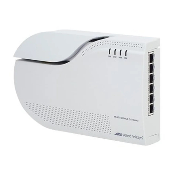
Puerta de Enlace
AT-iMG606BD
Allied Telesyn AT-iMG606BD Manuales
Manuales y guías de usuario para Allied Telesyn AT-iMG606BD. Tenemos
1
Allied Telesyn AT-iMG606BD manual disponible para descarga gratuita en PDF: Guia De Instalacion
Allied Telesyn AT-iMG606BD Guia De Instalacion (80 páginas)
Marca:
Allied Telesyn
| Categoría:
Puerta de Enlace
| Tamaño: 1.82 MB
Tabla de contenido
Tabla de Contenido
7
Preface
13
Safety Symbols Used in this Document
14
Table 1: Safety Symbols
14
Where to Find Web-Based Guides
15
Contacting Allied Telesyn
16
Online Support
16
Email and Telephone Support
16
Returning Products
16
Sales or Corporate Information
16
Management Software Updates
16
Chapter 1: Overview
18
Features
18
Gateway and Base Units
19
Gateway Unit
19
Figure 1: Front View
19
Figure 2: LAN Ports
19
Figure 3: Power Connector and Console Port
19
Base Unit
20
Figure 4: Base Unit
20
Ports
21
10/100Base-TX Ports
21
100Base-FX Fiber Uplink (WAN) Port
22
Leds
23
LAN Port Leds
23
Figure 5: LAN Port Leds
23
Table 2: LAN Port LED Descriptions
23
System Leds
24
Figure 6: System Leds
24
Table 3: System Leds
24
Power Connector
25
Console Connection
26
Chapter 2: Installation
28
Reviewing Safety Precautions
28
Selecting a Site for the Gateway
30
Planning the Installation
31
LAN Ports
31
Fiber Optic Uplink Port
31
Console Port
31
Table 4: Twisted Pair Cabling and Distances
31
Unpacking the AT-Img606Bd Multiservice Gateway
32
Installing the AT-Img606Bd Multiservice Gateway
33
Figure 7: Parts of the Base Unit
33
Figure 8: Location of Wall Anchor Holes
34
Figure 9: Mounting the Base to the Wall
34
Figure 10: Knockout Locations
35
Figure 11: Securing the Cable to the Base
35
Figure 12: Wrapping the Cable Around the Spindles
36
Figure 13: Threading the Cable through the Cover
36
Figure 14: Aligning the Screw Holes with the Posts
37
Figure 15: Attaching the Cover to the Base
37
Figure 16: Removing the Cover from the Post
38
Figure 17: Positioning the SC Connector
38
Figure 18: Securing the Cable in Position
38
Figure 19: Installing the Connector Cover
39
Figure 20: Removing the Plug from the Fiber Optic Port
39
Figure 21: Mounting the Gateway on the Base
40
Figure 22: AT-Img606Bd Multiservice Gateway Installed on the Base
40
Figure 23: Plugging in the Power Cord
41
Warranty Registration
42
Chapter 3 Troubleshooting
43
Appendix A: Technical Specifications
45
Physical Specifications
45
Environmental Specifications
45
Power Specifications
45
Safety and Electromagnetic Emissions Certifications
46
10/100Base-TX Port Pinouts
46
Figure 24: RJ-45 Connector and Port Pin Assignments
46
Table 5: 10/100Base-TX Port Pinouts
46
Table 6: 100Base-FX Fiber Optic Port
47
Publicidad
Publicidad
Productos relacionados
Allied Telesyn AT-8900 Serie
Allied Telesyn AT-9900 Serie
Allied Telesyn AT-9900s Serie
Allied Telesyn AT-8948
Allied Telesyn AT-8316F/MT
Allied Telesyn AT-8316F/VF
Allied Telesyn AT-8324
Allied Telesyn AT-B15/SX
Allied Telesyn AT-A24/LX
Allied Telesyn AT-8216FXL/MT
Allied Telesyn Categorias
Conmutadores de Red
Modules
Fuentes de Alimentación
Conversores de Medios
Puerta de Enlace
Más Allied Telesyn manuales
Login
Entrar
O
Iniciar sesión con Facebook
Iniciar sesión con Google
Cargar el manual
Cargar desde el disco
Cargar desde la URL