Tabla de contenido
Publicidad
Idiomas disponibles
Idiomas disponibles
Enlaces rápidos
Montage- und Bedienungsanleitung
Mounting instruction and operating manual
Notice de montage et d'emploi
Montagehandleiding en gebruiksaanwijzing
Istruzioni per il montaggio e l'uso
Instrucciones de montaje y funcionamiento
Starter Set Heizen – easy connect
DE
Starter Set Heating Control – easy connect
EN
Starter Set chauffage – easy connect
FR
Starter Set verwarming – easy connect
NL
Starter Set per il riscaldamento – easy connect
IT
Kit de inicio para calefacción – easy connect
ES
HmIP-SK9
S. 2
p. 34
p. 61
p. 83
p. 111
p. 146
Publicidad
Capítulos
Tabla de contenido

Manuales relacionados para HomeMatic IP Easy Connect

Resumen de contenidos para HomeMatic IP Easy Connect
- Página 1 Starter Set Heating Control – easy connect p. 61 Starter Set chauffage – easy connect p. 83 Starter Set verwarming – easy connect p. 111 Starter Set per il riscaldamento – easy connect p. 146 Kit de inicio para calefacción – easy connect HmIP-SK9...
-
Página 2: Lieferumfang
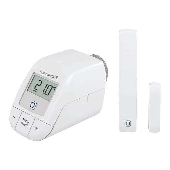
Lieferumfang Anzahl Bezeichnung Homematic IP Heizkörperthermostat – basic Homematic IP Fenster- und Türkontakt mit Magnet 1,5 V LR6/Mignon/AA Batterien 1,5 V LR03/Micro/AAA Batterien Adapter Danfoss RA Montagematerial Bedienungsanleitung Sicherheitshinweise Dokumentation © 2018 eQ-3 AG, Deutschland Alle Rechte vorbehalten. Ohne schriftliche Zustimmung des Herausgebers darf... - Página 5 5 mm 5 mm...
- Página 6 oder oder...
-
Página 7: Tabla De Contenido
Inhaltsverzeichnis Hinweise zur Anleitung ..............8 Funktion und Geräteübersicht ............8 Allgemeine Systeminformationen ..........10 Anlernen .................... 10 Direktes Anlernen...............11 Anlernen an den Access Point (alternativ) ....12 Montage .................... 13 Montage des Heizkörperthermostats ......13 Adaptierfahrt ..............16 Montage des Fenster- und Türkontakts ......17 Konfigurationsmenü... -
Página 8: Hinweise Zur Anleitung
Der Homematic IP Heizkörperthermostat kann die Raumtemperatur zeitgesteuert und bedarfsgerecht über ein Heizprofil mit individuellen Heizphasen regulieren. Der Homematic IP Fenster- und Türkontakt erkennt zuverlässig geöffnete Fenster bzw. Türen über einen Magnet- kontakt. Dadurch kann die Raumtemperatur bei geöffnetem Fenster automatisch abgesenkt werden. - Página 9 Funktion und Geräteübersicht Geräteübersicht Heizkörperthermostat (s. Abbildung 1): Überwurfmutter Batteriefach Display Systemtaste (Anlerntaste und LED) Minus-Taste Plus-Taste Menü-/Boost-Taste Geräteübersicht Fenster- und Türkontakt (s. Abbildung 1): Halterung Magnetkontakt Distanzstück (6 mm) für Magnetkontakt Elektronikeinheit Systemtaste (Anlerntaste und LED) Batteriefach Th Fr Sa Su Displayübersicht Heizkörperthermostat: Übersicht der Heizphasen Fr Sa Su...
-
Página 10: Allgemeine Systeminformationen
BOOST MANU Allgemeine Systeminformationen Offset Dieses Gerät ist Teil des Homematic IP Smart-Home-Systems und kommuniziert über das Homematic IP Funkprotokoll. Alle Geräte des Systems können komfortabel und individuell per Smartphone über die Homematic IP App konfiguriert werden. Alternativ haben Sie die Möglichkeit, Homematic ... -
Página 11: Direktes Anlernen
Sie können den Anlernvorgang durch erneute kurze Betäti- gung der Systemtaste (D) abbrechen. Dies wird durch rotes Aufleuchten der Geräte-LED (D) bestätigt. Um den Heizkörperthermostat an den Homematic IP Fenster- und Türkontakt mit Magnet anzulernen, müssen beide Geräte in den An- lernmodus gebracht werden. -
Página 12: Anlernen An Den Access Point (Alternativ)
Access Point anlernen möchten, müssen Sie die Werkseinstellungen der Geräte zuvor wiederherstellen (s. „10 Wiederherstellung der Werkseinstellungen“ auf Seite 30). Damit das Gerät in Ihr System integriert werden und per Homema- tic IP App gesteuert werden kann, muss es an den Homematic IP Ac-... -
Página 13: Montage
Montage cess Point angelernt werden. • Öffnen Sie die Homematic IP App auf Ihrem Smartphone. • Wählen Sie den Menüpunkt „Gerät anlernen“ aus. Ziehen Sie den Isolierstreifen aus dem Batteriefach (B bzw. M) des • Geräts heraus. Der Anlernmodus ist für 3 Minuten aktiv. - Página 14 Montage Die am Heizkörperthermostat angebrachte Überwurfmutter (A) ist uni- versell einsetzbar und ohne Zubehör passend für alle Ventile mit dem Gewindemaß M30 x 1,5 mm der gängigsten Hersteller (z. B. Heimeier, MNG, Junkers, Landis&Gyr (Duodyr), Honeywell-Braukmann, Oven- trop, Schlösser, Comap, Valf Sanayii, R.B.M, Jaga, Siemens und Idmar). Durch den im Lieferumfang enthaltenen Adapter ist das Gerät auch auf Heizkörperventile vom Typ Danfoss RA montierbar (s.
- Página 15 Sie den Thermostatkopf ab (P). Nach der Demontage des alten Thermostatkopfes können Sie den Homematic IP Heizkörperthermostat mit der Überwurfmutter (A) auf das Heizkörperventil aufsetzen (s. Abbildung 4). Bei Bedarf verwenden Sie den beiliegenden Adapter für Danfoss RA- Ventile (s.
-
Página 16: Adaptierfahrt
Montage Achten Sie darauf, sich nicht die Finger zwischen den Adap- terhälften einzuklemmen! Nach dem Aufrasten auf den Ventilkörper befestigen Sie die Adapter mit der beiliegenden Schraube und Mutter. 5.1.3 Stützring Bei Ventilen einiger Hersteller weist der in das Gerät hineinragende Teil des Ventils nur einen geringen Durchmesser auf, was zu einem lockeren Sitz führt. -
Página 17: Montage Des Fenster- Und Türkontakts
Montage Nachdem der Heizkörperthermostat erfolgreich montiert wurde, muss im nächsten Schritt zur Anpassung ans Ventil eine Adaptierfahrt (AdA) durchgeführt werden: • Wenn im Display „AdA“ steht, drücken Sie die Menü-/Boost-Taste (G), um die Adaptierfahrt zu starten. Der Heizkörperthermostat führt eine Adaptierfahrt durch. Dabei wer- den „AdA“... - Página 18 Montage Die Elektronikeinheit und der Magnetkontakt sollten sich möglichst auf der gleichen Höhe befinden. Dafür können Sie beim Magnetkontakt ein Distanzstück (J) einsetzen. Der ideale Abstand zwischen der Gehäusekante des Fenster- und Türkontakts und des Magnetkontakts beträgt 5 mm (s. Abbildung 6).
- Página 19 Montage Sie den Magnetkontakt an die gewünschte Position am Fenster. 5.3.3 Schraubmontage Setzen Sie den Magnetkontakt vor der Schraubmontage noch nicht zusammen. Für die Schraubmontage, gehen Sie wie folgt vor: • Bohren Sie die Schraublöcher in der Halterung (H) mit einem ge- eigneten Bohrer vor.
-
Página 20: Konfigurationsmenü Des Heizkörperthermostats
Mo Tu We Th Fr Sa Su Offset BOOST AUTO MANU MANU BOOST Bediensperre MANU Datum und Uhrzeit Offset Offset Offset Urlaubsmodus Wenn Sie das Gerät an den Access Point anlernen, können Sie die Einstellungen bequem über die Homematic IP App vornehmen. -
Página 21: Automatischer Betrieb
Gerät bereits direkt an ein anderes Home- matic IP Gerät angelernt haben, müssen Sie zum Anlernen des Heizkörperthermostats an einen Homematic IP Access Point oder an eine Zentrale CCU2/CCU3 zunächst die Werkseinstellungen des Geräts wiederherstellen (s. „10 Wie- derherstellung der Werkseinstellungen“... -
Página 22: Offset-Temperatur
Konfigurationsmenü des Heizkörperthermostats Zur Bestätigung blinkt das Symbol zweimal kurz auf und das Gerät wechselt in den manuellen Betrieb. 6.3 Offset-Temperatur Da die Temperatur am Heizkörperthermostaten gemessen wird, kann es an einer anderen Stelle im Raum kälter oder wärmer sein. Um dies anzugleichen, kann eine Offset-Temperatur von ±3.5 °C eingestellt werden. -
Página 23: Bediensperre
Konfigurationsmenü des Heizkörperthermostats Taste. • Bestätigen Sie die Startzeit 00:00 Uhr mit der Menü-Taste. • Wählen Sie über die Plus- oder Minus-Tasten die gewünschte Temperatur für die Startzeit aus und bestätigen Sie mit der Menü- Taste. • Im Display wird die nächste Uhrzeit angezeigt. Sie können diese Zeit über die Plus- oder Minus-Tasten verändern. -
Página 24: Uhrzeit Und Datum
Konfigurationsmenü des Heizkörperthermostats wechselt zurück zur Standardanzeige. Bei Aktivierung der Bediensperre wird das Symbol „Schloss“ im Display angezeigt. Um die Bediensperre zu deaktivieren, gehen Sie wie folgt vor: • Drücken Sie für ca. 2 s auf die Menü-Taste (G), um das Konfigura- tionsmenü... -
Página 25: Urlaubsmodus
Bedienung des Heizkörperthermostats 6.7 Urlaubsmodus Mo Tu We Th Fr Sa Su AUTO Der Urlaubsmodus kann genutzt werden, wenn für einen bestimmten BOOST Zeitraum dauerhaft eine feste Temperatur gehalten werden soll (z. B. MANU während eines Urlaubs oder einer Party). Um den Urlaubsmodus ein- zustellen, gehen Sie wie folgt vor: Offset Wählen Sie über die Plus- oder Minus-Tasten (E und F) den Menü-... -
Página 26: Batterien Wechseln
Batterien wechseln • Boost-Funktion: Drücken Sie die Boost-Taste (G) kurz, um die Boost-Funktion für schnelles, kurzzeitiges Aufheizen des Heizkör- pers durch Öffnung des Ventils zu aktivieren. Dadurch wird sofort ein angenehmes Wärmegefühl im Raum erreicht. Batterien wechseln Wird eine leere Batterie in der App bzw. am Gerät angezeigt, tauschen Sie die verbrauchten Batterien gegen neue Batterien aus. -
Página 27: Fehlerbehebung
Fehlerbehebung Vorsicht! Explosionsgefahr bei unsachgemäßem Austausch der Batterien. Ersatz nur durch denselben oder einen gleich- wertigen Typ. Batterien dürfen niemals aufgeladen werden. Batterien nicht ins Feuer werfen. Batterien nicht übermäßiger Wärme aussetzen. Batterien nicht kurzschließen. Es besteht Explosionsgefahr! Verbrauchte Batterien gehören nicht in den Hausmüll! Ent- sorgen Sie diese in Ihrer örtlichen Batteriesammelstelle! Fehlerbehebung 9.1 Befehl nicht bestätigt... -
Página 28: Fehlercodes Und Blinkfolgen
(also 36 Sekunden in einer Stunde). Die Geräte dürfen bei Erreichen des 1 %-Limits nicht mehr senden, bis diese zeitliche Begrenzung vo- rüber ist. Gemäß dieser Richtlinie, werden Homematic IP Geräte zu 100 % normenkonform entwickelt und produziert. Im normalen Be- trieb wird der Duty Cycle in der Regel nicht erreicht. - Página 29 Fehlerbehebung Kurzes oranges Anlernmodus Geben Sie die letzten vier Blinken aktiv Ziffern der Geräte-Serien- (alle 10 s) nummer zur Bestätigung ein (s. „4.2 Anlernen an den Access Point (alternativ)“ auf Seite 12). Schnelles oran- Direkter Anlern- Aktivieren Sie den Anlern- ges Blinken modus aktiv modus des anzulernenden...
-
Página 30: Wiederherstellung Der Werkseinstellungen
Wiederherstellung der Werkseinstellungen Mo Tu We Th Fr Sa Su AUTO BOOST Antennen- Kommunikati- Prüfen Sie die Verbindung MANU symbol ( ) blinkt onsstörung zum zum Access Point bzw. zu Offset Access Point den angelernten Geräten. oder zum ange- lernten Gerät We Th Fr Sa Su Schlosssymbol Bediensperre... -
Página 31: Wartung Und Reinigung
Wartung und Reinigung • Lassen Sie die Systemtaste wieder los. Drücken Sie die Systemtaste erneut für 4 s, bis die Geräte-LED (D • bzw. L) grün aufleuchtet. • Lassen Sie die Systemtaste wieder los, um das Wiederherstellen der Werkseinstellungen abzuschließen. Das Gerät führt einen Neustart durch. -
Página 32: Technische Daten
Technische Daten Hiermit erklärt die eQ-3 AG, Maiburger Str. 29, 26789 Leer, Deutsch- land, dass der Funkanlagentyp Homematic IP HmIP-eTRV-B und HmIP-SWDM der Richtlinie 2014/53/EU entspricht. Der vollständige Text der EU-Konformitätserklärung ist unter der folgenden Internetad- resse verfügbar: www.eq-3.de 13 Technische Daten... - Página 33 Technische Daten Fenster- und Türkontakt Geräte-Kurzbezeichnung: HmIP-SWDM Versorgungsspannung: 2x 1,5 V LR03/Micro/AAA Stromaufnahme: 35 mA max. Batterielebensdauer: 4 Jahre (typ.) Umgebungstemperatur: -10 bis +50 °C Abmessungen Elektronikeinheit (B x H x T): 102 x 18 x 25 mm Abmessungen Magnetkontakt (B x H x T): 48 x 11 x 13 mm Gewicht Elektronikeinheit: 46 g (inkl.
-
Página 34: Package Contents
Package contents Quantity Description Homematic IP Radiator Thermostat – compact Homematic IP Window / Door Contact with magnet 1.5 V LR6/mignon/AA batteries 1.5 V LR03/micro/AAA batteries Danfoss RA adapter Mounting accessories User manual Safety instructions Documentation © 2018 eQ-3 AG, Germany All rights reserved. - Página 35 Table of contents Information about this manual ............36 Function and device overview .............36 General system information ............38 Teaching-in ..................38 Direct pairing ..............39 Teaching-in to the Access Point (alternative) .....40 Installation ..................41 Installation of the radiator thermostat ......41 Adaption run ..............44 Mounting the window / door contact ......45 Configuration menu of the radiator thermostat ......48 Automatic operation ............49...
-
Página 36: Information About This Manual
Information about this manual Please read this manual carefully before beginning operation with your Homematic IP components. Keep the manual so you can refer to it at a later date if you need to. If you hand over the device to other persons for use, please hand over this manual as well. - Página 37 Function and device overview Device overview radiator thermostat (see figure 1): Union nut Battery compartment Display System button (teach-in button and LED) Minus button Plus button Menu/Boost button Device overview window and door contact (see figure 1): Bracket Magnet contact Spacer (6 mm) for magnetic contact Electronic unit System button (teach-in/pairing button and LED)
-
Página 38: General System Information
Offset This device is part of the Homematic IP smart home system and works with the Homematic IP radio protocol. All devices of the system can be configured comfortably and individually with the Homematic IP smartphone app. Alternatively, you can operate the Homematic IP devices via the Central Control Unit CCU2/CCU3 or in connection with various partner solutions. -
Página 39: Direct Pairing
(D) again. This will be indicated by the device LED (D) lighting up red. To connect the radiator thermostat to the Homematic IP Window / Door Contact with magnet, the pairing mode of both devices has to be activated. -
Página 40: Teaching-In To The Access Point (Alternative)
Access Point, you first need to restore the devices’ factory settings (see „10 Restore factory set- tings“ on page 57). To integrate the device into your system and to enable control via the Homematic IP app, you must teach-in the device to your... -
Página 41: Installation
Installation Homematic IP Access Point first. • Open the Homematic IP app on your smartphone. • Select the menu item “Teach-in device”. Remove the insulation strip from the battery compartment (B or • M) of the device. Teach-in mode remains activated for 3 minutes You can manually start the teach-in mode for another 3 min- utes by pressing the system button briefly (D or L) . - Página 42 Installation MNG, Junkers, Landis&Gyr (Duodyr), Honeywell-Braukmann, Oven- trop, Schlösser, Comap, Valf Sanayii, R.B.M, Jaga, Siemens or Idmar. By means of the adapter in the delivery, the device can be installed also on radiator valves of type Danfoss RA (see „5.1.1 Mounting the radiator thermostat“...
- Página 43 Installation matic IP Radiator Thermostat with the union nut (A) to the radiator valve (see figure 4). If required, you can use the supplied adapter for Danfoss RA valves (see „5.1.1 Mounting the radiator thermostat“ on page 42) or the supplied support ring (see „5.1.3 Support ring“ on page 44). 5.1.2 Danfoss RA adapter The provided adapter is required to attach to Danfoss RA valves.
-
Página 44: Adaption Run
Installation 5.1.3 Support ring The valves from different manufacturers may have tolerance fluctua- tions that make the radiator thermostat more loosely seated on the valve. In this case, the provided support ring (Q) should be placed into the flange before mounting the radiator thermostat (see figure 5). Adaption run Once the batteries have been inserted, the motor reserves. -
Página 45: Mounting The Window / Door Contact
Installation and the activity symbol ( ) are displayed. Wait until the adaption run is completed. Afterwards, the display returns back to normal. If the adapter run has been initiated prior to mounting or if an error message (F1, F2, F3) is displayed, press the menu/ boost button (G) and the motor reverses to the “InS”... - Página 46 Installation The ideal spacing between the housing edge of the window / door contact and the magnet contact should be 5 mm (see figure 6). 5.3.2 Adhesive strip mounting When using adhesive strips, make sure that the mounting surface is smooth, non-disturbed, free of dust, grease and solvents and not too cold.
- Página 47 Installation 5.3.3 Screw mounting Do not yet assemble the magnet contact before screw mounting. For screw mounting, please proceed as follows: • Pre-drill the screw holes in the brackets (H) using an appropriate drill. • Mark the screw holes for the electronic unit (K) according to the bracket on the window.
-
Página 48: Configuration Menu Of The Radiator Thermostat
Homematic IP app. If you have already adjusted the settings in the configuration menu or if you have already connected the device to another Homematic IP device, you first have to restore the factory... -
Página 49: Automatic Operation
Configuration menu of the radiatorthermostat settings of the device before you can connect it to a Homematic IP Access Point or another Central Control Unit CCU2/CCU3 (see „10 Restore factory settings“ on page 57). Automatic operation In automatic mode, the temperature is controlled in accordance with the set heating profile. -
Página 50: Programming A Heating Profile
Configuration menu of the radiatorthermostat temperature offset of ±3.5 °C can be set. If a nominal temperature of e.g. 20 °C is set but the room presents with only 18 °C, an offset of -2.0 °C needs to be set. An offset temperature of 0.0° is set in the factory settings. -
Página 51: Operating Lock
Configuration menu of the radiatorthermostat To confirm, the time flashes twice and the device changes back to the standard display. Operating lock Operation of the device can be locked to avoid settings being changed unintended (e.g. through involuntary touch). To activate the Mo Tu We Th Fr Sa Su AUTO operating lock, please proceed as follows:... -
Página 52: Holiday Mode
Configuration menu of the radiatorthermostat firm with the menu button. • Select the desired month using the plus or minus button and confirm with the menu button. • Select the desired day using the plus or minus button and con- firm with the menu button. -
Página 53: Operation Of The Radiator Thermostat
Operation of the radiator thermostat Operation of the radiator thermostat After teaching-in and mounting have been performed, simple opera- tions are available directly on the device. • Temperature: Press the left (E) or right (F) push-button to manu- ally change the temperature of the radiator. In automatic mode, the manually set temperature will remain the same until the next point at which the profile changes. -
Página 54: Troubleshooting
Troubleshooting • Please pay attention to the flashing signals of the device LED while inserting the batteries (see „9.3 Error codes and flashing sequences“ on page 55). Once the batteries have been inserted, the radiator thermostat will perform a self-test (approx. 2 seconds). Afterwards, initialisation is carried out. -
Página 55: Duty Cycle
1% of an hour (i.e. 36 seconds in an hour). Devices must cease transmission when they reach the 1% limit until this time restriction comes to an end. Homematic IP devices are de- signed and produced with 100 % conformity to this regulation. Dur- ing normal operation, the duty cycle is not usually reached. - Página 56 Troubleshooting 1x long green Transmission You can continue opera- lighting confirmed tion. 1x long red light- Transmission Please try again (see failed or duty sec. „9.1 Command not cycle limit is confirmed“ on page 54 reached or „9.2 Duty cycle“ on page 55).
-
Página 57: Restore Factory Settings
Restore factory settings Short orange Batteries empty Replace the batteries of lighting (after the device (see „8 Re- green or red placing batteries“ on page confirmation) 53). Mo Tu We Th Fr Sa Su AUTO BOOST Antenna Communication Please check the con- MANU symbol ( ) flash-... -
Página 58: Maintenance And Cleaning
Maintenance and cleaning until the LED will quickly start flashing orange (see figure 2). • Release the system button again. • Press and hold down the system button again for 4 seconds, until the device LED (D or L) lights up green. •... -
Página 59: Technical Specifications
Technical specifications Hereby, eQ-3 AG, Maiburger Str. 29, 26789 Leer/Germany declares that the radio equipment types Homematic IP HmIP-eTRV-B and HmIP-SWDM are in compliance with Directive 2014/53/EU. The full text of the EU declaration of conformity is available at the following internet address: www.eq-3.com... - Página 60 Technical specifications Window and Door Contact Device short name: HmIP-SWDM Supply voltage: 2x 1.5 V LR03/micro/AAA Current consumption: 35 mA max. Battery life: 4 years (typ.) Ambient temperature: -10 to +50 °C Dimensions electronic unit (W x H x D): 102 x 18 x 25 mm Dimensions magnet contact (W x H x D): 48 x 11 x 13 mm...
-
Página 61: Pack De Livraison
Pack de livraison Nombre Désignation Thermostats de radiateur Homematic IP – basic Contact de fenêtre et de porte Homematic IP avec aimant Piles 1,5 V LR6/Mignon/AA Piles 1,5 V LR03/Micro/AAA Adaptateur Danfoss RA Matériel de montage Mode d'emploi Consignes de sécurité... - Página 62 Table des matières Remarques sur la notice ..............63 Fonction et aperçu de l’appareil ..........63 Informations générales sur le système ........65 Apprentissage...................65 Apprentissage direct ............66 Programmation sur le Access Point (alternative) ..67 Montage ....................69 Montage des thermostats de radiateur ......69 Trajet d’adaptation ............
-
Página 63: Remarques Sur La Notice
Le contact de fenêtre et de porte Homematic IP détecte en toute fiabilité des fenêtres ou des portes ouvertes via un contact magnétique. Ainsi, la température ambiante peut-elle être automatiquement abaissée si des fenêtres... - Página 64 Fonction et aperçu de l’appareil Aperçu de l’appareil thermostats de radiateur (v. figure 1) : Écrou-chapeau Compartiment à piles Écran Touche système (touche de programmation et LED) Touche moins Touche plus Touche menu/boost Aperçu de l’appareil contact de fenêtre et de porte (v. figure 1) : Support Contact magnétique Entretoise (6 mm) pour contact magnétique...
-
Página 65: Informations Générales Sur Le Système
Homematic IP. Tous les appareils peuvent être configurés facilement et individuellement avec un smartphone à l’aide de l’application Homematic IP o du la centrale CCU2/CCU3. Vous trouverez dans le manuel de l’utilisateur Homematic IP l’étendue des fonctions du système Homematic IP en... -
Página 66: Apprentissage Direct
LED (D) . Afin de programmer les thermostats de radiateur sur le contact de fenêtre et de porte Homematic IP avec aimant, les deux appareils doivent être mis en mode d’apprentissage. •... -
Página 67: Programmation Sur Le Access Point (Alternative)
4.2 Programmation sur le Access Point (alternative) Vous pouvez programmer l’appareil sur le Homematic IP Access Point ou sur la centrale CCU2/CCU3. Vous trouverez de plus amples informations à ce sujet dans le manuel de l’utilisateur IP (à... - Página 68 (v. „10 Rétablissement des réglages d’usine“ à la page 85). Pour que l’appareil puisse être intégré dans votre système et être commandé via l’application Homematic IP, vous devez d’abord pro- céder à son apprentissage avec l’Homematic IP Access Point. •...
-
Página 69: Montage
Montage vous voulez utiliser votre appareil. • Donnez un nom à l’appareil dans l’application et attribuez-le à une pièce. Montage 5.1 Montage des thermostats de radiateur Le montage des thermostats de radiateur peut s’effectuer sans qu’il ne soit nécessaire de laisser couler de l’eau ni d’intervenir sur le sys- tème de chauffage. - Página 70 Raccord-union avec vis sans tête : Dévissez la vis sans tête et re- tirez la tête thermostatique (P). Après le démontage de l’ancienne tête thermostatique, vous pouvez poser le thermostat de radiateur Homematic IP avec l’écrou-chapeau (A) (v. figure 4). Si nécessaire, utilisez l’adaptateur annexé pour les vannes Danfoss RA (v.
- Página 71 Montage quis. Le cas échéant, utilisez un tournevis afin de plier légèrement l’adaptateur (v. figure ci-après). Les corps de vanne de Danfoss présentent des encoches longitudi- nales circulaires (1) qui garantissent une meilleure assise de l’adapta- teur après l’enclenchement. Lors du montage, veillez à ce que les broches à l’intérieur de l’adaptateur (2) aient une position coïncidant avec les en- coches (1) de la vanne.
-
Página 72: Trajet D'aDaptation
Montage 5.1.3 Anneau de support Sur les vannes de quelques fabricants, la pièce de l’appareil engagée dans l’appareil ne présente qu’un faible diamètre, ce qui entraîne une moindre solidité. Dans ce cas-ci, l’anneau de support (Q) doit être inséré dans la bride de l’appareil avant le montage (v. figure 5). 5.2 Trajet d’adaptation Après l’insertion des piles, le moteur recule pour faciliter le montage. -
Página 73: Montage De La Bande Adhésive
Montage de fenêtre et de la porte. • Fixez une partie du contact de fenêtre et de porte (contact ma- gnétique (I) ou l’unité électronique (K) sur la partie mobile (vantail de porte ou de fenêtre), l’autre sur la partie fixe (cadre) de la fe- nêtre ou de la porte (v. - Página 74 Montage • Placez la grande bande adhésive à deux côtés sur la partie arrière du support (H) (v. figure 7) et appuyez sur l’appareil pour qu’il se trouve en position souhaitée. • Insérez l’aimant dans le support de la partie arrière et insérez la partie arrière dans le boîtier du contact magnétique.
-
Página 75: Menu De Configuration Des Thermostats De Radiateur
Menu de configuration des thermostats de radiateur montage souhaitée et tournez les deux vis (2,2 x 16 mm) à travers les trous de vis (v. figure 8). • Insérez l’unité électronique dans le support. • Maintenez le côté arrière du contact magnétique ou l’entretoise dans la position de montage souhaitée et tournez les deux vis (2,2 x 13 mm) à... -
Página 76: Mode Automatique
Mode vacances Lorsque vous programmez l’appareil sur l’Access Point, vous pouvez entreprendre les réglages en tout confort via l’application Homematic IP. Si vous avez déjà entrepris des réglages dans le menu de configuration ou si vous avez programmé l’appareil directe- ment sur un autre appareil IP Access Point ou sur une cen- trale CCU2/CCU3, rétablir tout d’abord les réglages d’usine... -
Página 77: Mode Manuel
Menu de configuration des thermostats de radiateur et l’appareil passe en mode automatique. 6.2 Mode manuel En mode manuel, le réglage de la température s’effectue conformé- ment à la température réglée via les touches (E et F). La température reste active jusqu’à la prochaine modification manuelle. Afin d’activer le mode manuel, procédez comme suit : •... -
Página 78: Programmation D'uN Profil De Chauffage
Menu de configuration des thermostats de radiateur 6.4 Programmation d’un profil de chauffage Sous ce point de menu, vous avez la possibilité de réaliser un profil de chauffage avec six phases de chauffage et de diminution (13 mo- ments de commutation) selon vos propres souhaites. •... -
Página 79: Heure Et Date
Menu de configuration des thermostats de radiateur • Sélectionnez « On » via les touches plus ou moins afin d’activer le verrouillage de commande ou « OFF » pour désactiver le ver- rouillage de commande et confirmer avec la touche menu. Pour confirmer l’opération, la sélection clignote brièvement deux fois et l’appareil revient à... -
Página 80: Mode Vacances
Utilisation des thermostats de radiateur mez avec la touche menu. Pour confirmer l’opération, l’heure clignote brièvement deux fois et l’appareil revient à l’affichage standard. Mo Tu We Th Fr Sa Su 6.7 Mode vacances AUTO BOOST Le mode vacances peut être utilisé lorsque, pour une période déter- MANU minée, une température fixe doit être maintenue durablement (par ex. -
Página 81: Changer Les Piles
Changer les piles réglé est de nouveau activé. En mode manuel, la température reste conservée jusqu’à la prochaine modification. • Fonction boost : Appuyez brièvement sur la touche boost (G) pour activer la fonction boost pour un chauffage rapide, à court terme du radiateur par l’ouverture de la vanne. -
Página 82: Correction Des Erreurs
Correction des erreurs Attention ! Risque d’explosion lors du remplacement incor- rect des piles. Remplacement par le même type ou un type équivalent. Les piles ne peuvent jamais être rechargées. Ne pas jeter les piles dans le feu. Ne pas exposer les piles à une chaleur excessive. -
Página 83: Codes D'eRreur Et Séquences De Clignotement
Correction des erreurs vaillent dans une plage 868 MHz. Dans la plage de fréquences que nous utilisons (868 MHz), le temps d’émission maximal de chaque ap- pareil s’élève à 1 % d’une heure (donc 36 secondes dans une heure). Les appareils ne peuvent plus émettre lorsque la limite 1 % est atteinte, jusqu’à... - Página 84 Correction des erreurs Court clignotement Mode de pro- Saisissez les quatre der- orange grammation actif niers chiffres du numéro (toutes les 10 s) de série de l'appareil pour la confirmation (v. „4.2 Programmation sur le Access Point (alterna- tive)“ à la page 67). Bref clignotement Mode de pro- Activez le mode de...
-
Página 85: Rétablissement Des Réglages D'uSine
Rétablissement des réglages d’usine u We Th Fr Sa Su Symbole de verrou Blocage de com- Désactivez le blocage mande actif de commande dans l'application. 6 x long clignote- Appareil défec- Faites attention à ment rouge tueux l'affichage dans votre application et adressez-vous à... -
Página 86: Maintenance Et Nettoyage
Le soussigné, eQ-3 AG, Maiburger Str. 29, 26789 Leer/Germany, dé- clare que l’équipement radioélectrique du type Homematic IP HmIP-... -
Página 87: Caractéristiques Techniques
Caractéristiques techniques eTRV-B e HmIP-SWDM sont conforme à la directive 2014/53/UE. Le texte complet de la déclaration UE de conformité est disponible à l’adresse internet suivante: www.eq-3.com. Caractéristiques techniques Bande de fréquences radio : 868,0-868,6 MHz 869,4-869,65 MHz Puissance d’émission radio maximale : 10 dBm Catégorie du récepteur : SRD category 2... - Página 88 Caractéristiques techniques Tension d’alimentation : 2x 1,5 V LR03/Micro/AAA Consommation de courant : 35 mA max. Durée de vie de la pile : 4 ans (typ.) Température ambiante : -10 à +50 °C Dimensions unité électronique (l x h x p) : 102 x 18 x 25 mm Dimensions contact magnétique (l x h x p) :...
- Página 89 Caractéristiques techniques Levering Hoeveelheid Omschrijving Homematic IP radiatorthermostaat – basic Homematic IP raam- en deurcontact met magneet 1,5 V LR6/Mignon/AA batterijen 1,5 V LR03/Micro/AAA batterijen Adapter Danfoss RA Montagemateriaal Gebruikershandleiding Veiligheidsvoorschriften Documentatie © 2018 eQ-3 AG, Duitsland Alle rechten voorbehouden. Geen enkel deel van deze handleiding mag,...
- Página 90 Caractéristiques techniques Inhoud Instructies voor de handleiding ........... 91 Functie- en apparaatoverzicht ............. 91 Algemene systeeminformatie ............93 Koppelen ...................93 Directe training ..............94 Koppelen aan het Access Point (alternatief) ....95 Montage ....................96 Montage van de radiatorthermostaat ......96 Adapteerbeweging ............99 Montage van de venster- en deurcontacten ....100 Configuratiemenu van de radiatorthermostaat ......102 Automatische bediening ..........104 Handmatige modus ............104...
-
Página 91: Instructies Voor De Handleiding
Als alternatief kunt u, in combinatie met een Homema- tic IP Access Point, de apparaten eenvoudig en gratis via de smartp- hone-app integreren in het Homematic IP Smart Home-systeem en deze inzetten voor uitgebreide binnenklimaat- en beveiligingstoepas- singen. - Página 92 Functie- en apparaatoverzicht Apparaatoverzicht radiatorthermostaat (zie afbeelding 1): Wartelmoer Batterijcompartiment Display Systeemtoets (teach-in-toets en LED) Min-toets Plus-toets Menu-/Boost-toets Apparaatoverzicht venster- en deurcontact (zie afbeelding 1): Houder Magneetcontact Afstandsstuk (6 mm) voor magnetisch contact Elektronica-eenheid Systeemtoets (teach-in-toets en LED) Batterijcompartiment Th Fr Sa Su Overzicht van het display radiatorthermostaat: Overzicht van de verwarmingsfasen Fr Sa Su...
-
Página 93: Algemene Systeeminformatie
Algemene systeeminformatie Dit apparaat is een onderdeel van het domoticasysteem Homematic Offset IP en communiceert via het Homematic IP zendprotocol. Alle Home- matic IP-apparaten kunnen met een smartphone comfortabel en in- dividueel via de Homematic IP-app worden geconfigureerd of met de centrale CCU2/CCU3. -
Página 94: Directe Training
Koppelen 4.1 Directe training U kunt de Homematic IP radiatorthermostaat - basis (HmIP- eTRV-B) aan het Homematic IP-venster en deurcontact met magneet (HmIP-SWDM) direct aan elkaar koppelen. Houd tijdens het koppelen een afstand van minimaal 50 cm aan tussen de apparaten. -
Página 95: Koppelen Aan Het Access Point (Alternatief)
4.2 Koppelen aan het Access Point (alternatief) U kunt het toestel aan het Homematic IP Access Point of aan de centrale CCU2/CCU3 koppelen. Meer informatie hierover vindt u in het Homematic IP-handboek (terug te vinden in het downloadgedeelte van de website www.eQ-3.com). -
Página 96: Montage
Home- matic IP Access Point worden gekoppeld. • Open de Homematic IP-app op uw smartphone. Selecteer het menu-item ‘Apparaat koppelen’ . • Verwijder de isolerende strip uit het batterijcompartiment (B of M) •... - Página 97 Montage zijn niet nodig. De wartelmoer (A) die is bevestigd aan de radiatorthermostaat is uni- verseel toepasbaar en zonder accessoires geschikt voor alle kleppen met de schroefdraadmaat M30 x 1,5 mm van de meest voorkomende fabrikanten (bv. Heimeier, MNG, Junkers, Landis & Gyr (Duodyr), Ho- neywell-Braukmann, Oventrop, Schlösser, Comap, Valf Sanayii, RBM, Jaga, Siemens en Idmar).
- Página 98 Montage tegen de klok in te draaien (O). Daarna kunt u de thermostaatkop wegnemen (P). • Klemschroeven: De thermostaatknop wordt door een bevesti- gingsring vastgehouden, die met een schroef samengehouden wordt. Draai deze schroef los en neem de thermostaatkop van het ventiel af (P).
-
Página 99: Adapteerbeweging
Montage Let erop dat u uw vingers niet tussen de adapterhelften klemt! Na het vastklikken op het kraanhuis, dient u de adapter met de bijge- leverde schroef en moer te bevestigen. 5.1.3 Steunring Bij kranen van bepaalde fabrikanten heeft het deel van de kraan dat in het apparaat zit, een kleine diameter, zodat het apparaat loszit. -
Página 100: Montage Van De Venster- En Deurcontacten
Montage ging (AdA) worden uitgevoerd: • Als het display “AdA” aangeeft, drukt u op de menu / boost-knop (G), om de adapteerbeweging te starten. De radiatorthermostaat voert een adapteerbeweging uit. Ondertussen worden “AdA” en het activiteitspictogram ( ) op ht display weergege- ven. - Página 101 Montage De elektronische eenheid en het magnetische contact moe- ten op dezelfde hoogte geplaatst worden. U kunt bij het mag- netische contact daarvoor een afstandsstuk (J) gebruiken. De ideale afstand tussen de rand van de behuizing van het venster- en het deurcontact en het magneetcontact is 5 mm (zie afbeelding 6).
-
Página 102: Configuratiemenu Van De Radiatorthermostaat
Bij gebruik van het afstandsstuk kunt u na de montage een- voudig het magneetcontact op het afstandsstuk plaatsen. Configuratiemenu van de radiatorthermostaat Als u de radiatorthermostaat zonder een Homematic IP-Access Point gebruikt, kunt u na de inbedrijfstelling de volgende modi selecteren en instellingen in het configuratiemenu aanbrengen om het apparaat... - Página 103 Offset Vakantiemodus Als u het apparaat naar het Access point koppelt, kunt u de instellingen makkelijk via de Homematic IP-app doen. Als u al instellingen heeft gedaan in het configuratiemenu, of het apparaat al heeft gekoppeld aan een ander Homematic...
-
Página 104: Automatische Bediening
Configuratiemenu van de radiatorthermostaat 6.1 Automatische bediening In de automatische modus vindt de temperatuurregeling plaats vol- gens het ingestelde verwarmingsprofiel. Handmatige wijzigingen blij- ven actief tot de volgende schakeltijd. Daarna wordt het ingestelde verwarmingsprofiel opnieuw geactiveerd. Om de automatische be- diening te activeren, gaat u als volgt te werk: •... -
Página 105: Een Verwarmingsprofiel Programmeren
Configuratiemenu van de radiatorthermostaat • Kies met de Plus- en Min-toetsen (E en F) het menupunt “Auto” . • Bevestig met de menu-toets. • Kies met de Plus- en Min-toetsen de gewenste offset-tempera- tuur en bevestig door op de menu-toets te drukken. Ter bevestiging knippert de temperatuur tweemaal kort en keert het apparaat terug naar het standaardscherm. -
Página 106: Bedieningsvergrendeling
Configuratiemenu van de radiatorthermostaat 6.5 Bedieningsvergrendeling De bediening aan het apparaat kan worden vergrendeld, om te voor- komen dat instellingen ongewenst worden gewijzigd, bv. door per ongeluk aanraken te verhinderen. Om de bedieningsvergrendeling te Mo Tu We Th Fr Sa Su AUTO activeren/ deactiveren, gaat u als volgt te werk: BOOST... -
Página 107: Vakantiemodus
Configuratiemenu van de radiatorthermostaat menu-toets. • Kies via de Plus- of Min-toetsen de dag en bevestig met de me- nu-toets. • Kies via de Plus- of Min-toetsen het uur en bevestig met de me- nu-toets. • Kies via de Plus- of Min-toetsen de minuten en bevestig met de menu-toets. -
Página 108: Bediening Van De Radiatorthermostaat
Bediening van de radiatorthermostaat Bediening van de radiatorthermostaat Wanneer het apparaat gekoppeld is en in een stopcontact gestoken is, zijn de eenvoudige bedieningsfuncties direct aan het apparaat be- schikbaar. • Temperatuur: Druk op de linker (E) of rechtse (F) toets, om de tem- peratuur van de radiator manueel aan te passen. -
Página 109: Storingen Oplossen
Storingen oplossen • Sluit het batterijcompartiment weer. • Let na het plaatsen van de batterijen op de knipperende reeksen van de LED (zie „9.3 Foutcodes en knipperreeksen“ op pagina 110). Na het plaatsen van de batterijen voert de radiatorthermostaat gedu- rende 2 seconden een zelftest uit. -
Página 110: Duty Cycle
1%-limiet niet meer zenden, tot deze tijdelijke begren- zing weer voorbij is. In overeenstemming met deze richtlijn worden Homematic IP-apparaten 100% conform aan de normen ontwikkeld en geproduceerd. Tijdens de normale werking wordt de duty cycle doorgaans niet bereikt. Dit kan echter in individuele gevallen het ge- val zijn bij de inbedrijfstelling of de initiële installatie van een systeem... - Página 111 Storingen oplossen 1x lang groen Proces U kunt verdergaan met de oplichten bevestigd bediening. 1x lang rood op- Proces mislukt of Probeer het opnieuw (zie lichten Duty Cycle-Limit „9.1 Commando niet be- bereikt vestigd“ op pagina 109 of „9.2 Duty Cycle“ op pagina 110).
- Página 112 Storingen oplossen Batterijsymbool Noodpositie van Vervang de batterijen van ( ) en --- de klep werd het apparaat. (zie „8 Bat- benaderd terijen wisselen“ op pagina 108). Kort oranje op- Batterijen leeg Vervang de batterijen van lichten (na groene het apparaat. (zie „8 Bat- of rode ontvangs- terijen wisselen“...
-
Página 113: Reset De Fabrieksinstellingen
Reset de fabrieksinstellingen Reset de fabrieksinstellingen De fabrieksinstellingen van het apparaat kunnen worden ge- reset. Hierbij gaan alle instellingen verloren. Om de fabrieksinstellingen van het apparaat te resetten, gaat u als volgt te werk: Open het batterijcompartiment (B of M) van het toestel (zie af- •... -
Página 114: Algemene Richtlijnen Voor Het Draadloze Verkeer
Hierbij verklaar ik, eQ-3 AG, Maiburger Str. 29, 26789 Leer/Germany, dat het type radioapparatuur Homematic IP HmIP-eTRV-B en HmIP- SWDM conform zijn met Richtlijn 2014/53/EU. De volledige tekst van de EU-conformiteitsverklaring kan worden geraadpleegd op het vol- gende internetadres: www.eq-3.com... - Página 115 Technische gegevens Voedingsspanning: 2x 1,5 V LR6/Mignon/AA Stroomopname: 100 mA max. Levensduur batterijen: 2 jaar (type) Omgevingstemperatuur: 0 tot 50 °C Werkwijze: Type 1 Verontreinigingsgraad: Afmetingen (B x H x D): 57 x 68 x 102 mm Gewicht: 185 g (incl. batterijen) Typ.
- Página 116 Technische gegevens Verwijderingsbeleid Doe het toestel niet bij het huisvuil! Elektronische apparaten moeten worden afgevoerd in overeenstemming met de richtlijn betreffende afgedankte elektrische en elektronische apparatuur via plaatselijke inzamelpunten voor elektronisch afval. Conformiteitsinstructies Het CE-merk is een markering voor vrije handel, dat uitslui- tend aan de autoriteiten is gericht en geen garantie voor bepaalde eigenschappen inhoudt.
- Página 117 Fornitura Quantità Denominazione Termostato per radiatore Homematic IP – basic Contatto per finestra e porta con magnete Homematic IP Batterie LR6/mignon/AA da 1,5 V Batterie LR03/micro/AAA da 1,5 V Adattatore Danfoss RA Materiale di montaggio Istruzioni per l’uso Indicazioni di sicurezza Documentazione ©...
- Página 118 Indice Note su queste istruzioni ............. 119 Funzione e vista d’insieme dell’apparecchio ......119 Informazioni generali sul sistema ..........121 Autoapprendimento ..............121 Apprendimento diretto ..........122 Autoapprendimento all’Access Point (alternativo) ... 123 Montaggio ..................125 Montaggio del termostato per radiatore ....125 Corsa di adattamento ............128 Montaggio del contatto per finestra e porta .....
-
Página 119: Note Su Queste Istruzioni
Funzione e vista d’insieme dell’apparecchio Il termostato per radiatore Homematic IP è in grado di regolare la temperatura di una stanza in modo temporizzato e in base alle esi- genze specifiche mediante un profilo di riscaldamento con fasi di riscaldamento personalizzate. - Página 120 Funzione e vista d’insieme dell’apparecchio Vista d’insieme termostato per radiatore (v. immagine 1): Dado di raccordo Vano batterie Display Tasto di sistema (tasto di apprendimento e LED) Tasto meno Tasto più Tasto menù/boost Vista d’insieme contatto per finestra e porta (v. immagine 1): Supporto Contatto magnetico Distanziatore (6 mm) per contatto magnetico...
-
Página 121: Informazioni Generali Sul Sistema
L’autoapprendimento può essere effettuato associando gli apparecchi gli uni agli altri o allo Homematic IP Access Point (HmIP-HAP). In caso di au- toapprendimento diretto la configurazione avviene sull’apparecchio (ad es. mediante il termostato per radiatore) e in caso di autoapprendimento... -
Página 122: Apprendimento Diretto
LED rossa dell’ (D) apparecchio. Per l’apprendimento del termostato per radiatore associato al con- tatto per finestra e porta Homematic IP con magnete, entrambi gli apparecchi devono essere portati in modalità di apprendimento. • Togliere le strisce isolanti dal vano batterie del termostato per ra- diatore (B) e del contatto per finestra e porta (M). -
Página 123: Autoapprendimento All'ACcess Point (Alternativo)
Se si utilizzano svariati apparecchi in una stanza, si dovrebbe effettuare l’apprendimento tutti apparecchi associandoli. 4.2 Autoapprendimento all’Access Point (alternativo) L’autoapprendimento dell’apparecchio può essere effettua- to all’Homematic IP Access Point o alla centrale CCU2/ CCU3. Ulteriori informazioni sono disponibili nel manuale utente Homematic (nell’area download sito www.eQ-3.com). - Página 124 (v. „10 Ripristino delle impostazioni di fabbrica“ a pagina 142). Per fare in modo che l’apparecchio possa essere integrato e coman- dato dall’app Homematic IP, dapprima deve essere associato all’Ho- mematic IP Access Point. •...
-
Página 125: Montaggio
Montaggio • Nell’app assegnare un nome all’apparecchio e associarlo a una stanza. Montaggio 5.1 Montaggio del termostato per radiatore Il montaggio del termostato per radiatore può essere eseguito senza scaricare l’acqua di riscaldamento o intervenire sul sistema di riscal- damento. Non sono necessari un’attrezzatura speciale o lo spegni- mento del riscaldamento. - Página 126 (P). Dopo aver smontato la testa del termostato è possibile collocare il radiatore per termostato Homematic IP con il dado di raccordo (A) sulla valvola del radiatore (v. immagine 4). Se necessario, utilizzare l’adattatore in dotazione per valvole Danfoss RA (v.
- Página 127 Montaggio 5.1.2 Adattatore per Danfoss RA Per il montaggio sulle valvole RA di Danfoss è necessario l’adattato- re in dotazione. Eventualmente utilizzare un cacciavite, per allargare leggermente l’adattatore (v. immagine seguente). I corpi delle valvole Danfoss hanno delle incisioni allungate su tutto il perimetro (1) , che garantiscono un posizionamento migliore dell’a- dattatore dopo l’inserimento.
-
Página 128: Corsa Di Adattamento
Montaggio 5.1.3 Anello di appoggio Nelle valvole di alcuni produttori la parte della valvola inserita nell’ap- parecchio ha solo un diametro limitato, il che determina un posizio- namento non sufficientemente aderente. In questo caso andrebbe applicato l’anello di supporto in dotazione (Q) prima del montaggio nella flangia dell’apparecchio (v. -
Página 129: Montaggio Del Contatto Per Finestra E Porta
Montaggio 5.3 Montaggio del contatto per finestra e porta 5.3.1 Scelta della posizione di montaggio adeguata • Scegliere la finestra o la porta per il montaggio del contatto per finestra e porta. • Fissare una parte del contatto per finestra e porta (contatto ma- gnetico (I) o unità... - Página 130 Montaggio procedere come segue: • Applicare la striscia adesiva doppia e di grandi dimensioni sul lato posteriore del supporto (H) (v. immagine 7) e premere l’apparec- chio nella posizione desiderata. • Inserire il magnete nel supporto del lato posteriore e il lato poste- riore nell’alloggiamento del contatto magnetico.
-
Página 131: Menù Di Configurazione Del Termostato Per Radiatore
Menù di configurazione del termostato per radiatore Se si utilizza il termostato per radiatore senza Homematic IP Access Point, dopo la messa in funzione è possibile selezionare le seguenti modalità ed eseguire le impostazioni sull’apparecchio tramite il menù di configurazione per adattare l’apparecchio alle esigenze personali. -
Página 132: Funzionamento Automatico
Ho- mematic IP, per l’apprendimento del termostato per radia- tore a un Homematic IP Access Point o ad una centrale CCU2/CCU3 è prima necessario ripristinare le impostazioni di fabbrica dell’apparecchio (v. „10 Ripristino delle imposta- zioni di fabbrica“... -
Página 133: Funzionamento Manuale
Menù di configurazione del termostato per radiatore “Auto”. • Confermare la selezione con il tasto menù. La selezione risulta confermata se il simbolo lampeggia brevemente due volte e l’apparecchio passa al funzionamento automatico. 6.2 Funzionamento manuale* Nel funzionamento manuale, la regolazione della temperatura av- viene in base alla temperatura impostata mediante i tasti (E e F). -
Página 134: Programmazione Di Un Profilo Di Riscaldamento
Menù di configurazione del termostato per radiatore • Utilizzando i tasti più o meno selezionare la temperatura offset desiderata e confermare la selezione con il tasto menù. La selezione risulta confermata se la temperatura lampeggia breve- mente due volte e l’apparecchio torna alla visualizzazione standard. 6.4 Programmazione di un profilo di riscaldamento Questa voce di menù... -
Página 135: Blocco Comandi
Menù di configurazione del termostato per radiatore 6.5 Blocco comandi L’utilizzo dell’apparecchio può essere bloccato per impedire modi- fiche involontarie di impostazioni, ad esempio in caso di contatto fortuito. Per attivare o disattivare il blocco comandi procedere nel modo seguente: Tu We Th Fr Sa Su Utilizzando i tasti più... -
Página 136: Modalità Vacanza
Menù di configurazione del termostato per radiatore scelta con il tasto menù. • Utilizzando i tasti più o meno selezionare il mese e confermare la scelta con il tasto menù. • Utilizzando i tasti più o meno selezionare il giorno confermare la scelta con il tasto menù. -
Página 137: Utilizzo Del Termostato Per Radiatore
Utilizzo del termostato per radiatore La selezione risulta confermata se il simbolo lampeggia brevemente due volte e l’apparecchio passa alla modalità vacanza. Utilizzo del termostato per radiatore Dopo l’autoapprendimento e il montaggio, direttamente sull’appa- recchio sono disponibili semplici funzioni di comando. •... - Página 138 Sostituzione delle batterie Per il termostato per radiatore utilizzare due batterie da 1,5 V LR6/Micro/AA e per il contatto per finestra e porta due batterie da 1,5 V LR03/Micro/AAA. • Richiudere il vano batterie. • Dopo aver posizionato le batterie fare attenzione alle sequenze di lampeggio dei LED (v.
-
Página 139: Risoluzione Dei Guasti
1% gli apparecchi non devono più trasmettere fino a che non è trascorsa la limitazione di tempo. In conformità a que- sta direttiva, gli apparecchi Homematic IP sono sviluppati e prodotti nel pieno rispetto delle norme. Nel funzionamento normale il Duty Cycle di regola non viene raggiunto. -
Página 140: Codici Di Errore E Sequenze Di Lampeggio
Risoluzione dei guasti dell’apparecchio. Dopo breve tempo (max. 1 ora) il funzionamento dell’apparecchio risulta ripristinata. 9.3 Codici di errore e sequenze di lampeggio Codice di lampeg- Significato Soluzione gio/ Visualizzazio- ne sul display Breve lampeggio Trasmissione Attendere che la tra- arancione radio/tentativo smissione sia conclusa. - Página 141 Risoluzione dei guasti Attuatore valvola Controllare se lo poco scorrevole stantuffo della valvola di riscaldamento si è bloccato. Intervallo di Controllare il fissag- impostazione gio del termostato per troppo esteso radiatore Intervallo di Controllare se lo impostazione stantuffo della valvola troppo piccolo di riscaldamento si è...
-
Página 142: Ripristino Delle Impostazioni Di Fabbrica
Ripristino delle impostazioni di fabbrica We Th Fr Sa Su Simbolo serratura Blocco comandi Disattivare il blocco attivo comandi nell'app. 6x lampeggio lun- Apparecchio Prestare attenzione alla go rosso difettoso visualizzazione nell'app o rivolgersi al proprio rivenditore specializzato. 1x accensione Indicazione di Allo spegnimento arancio e 1x accen-... -
Página 143: Manutenzione E Pulizia
Il fabbricante, eQ-3 AG, Maiburger Str. 29, 26789 Leer/Germany, di- chiara che il tipo di apparecchiatura radio Homematic IP HmIP-e- TRV-N e HmIP-SWDM è conforme alla direttiva 2014/53/UE. Il testo... -
Página 144: Dati Tecnici
Dati tecnici completo della dichiarazione di conformità UE è disponibile al se- guente indirizzo Internet: www.eq-3.com Dati tecnici Banda di frequenza radio: 868,0-868,6 MHz 869,4-869,65 MHz Potenza delle trasmissioni RF max.: 10 dBm Categoria di ricezione: SRD category 2 Duty Cycle: <... - Página 145 Dati tecnici Tensione di alimentazione: 2x 1,5 V LR03/micro/AAA Corrente assorbita: 35 mA max. Durata batterie: 4 anni (tip.) Temperatura ambiente: -10 bis +50°C Dimensioni unità elettronica (L x A x P): 102 x 18 x 25 mm Dimensioni contatto magnetico (L x A x P): 48 x 11 x 13 mm Peso unità...
-
Página 146: Volumen De Suministro
Volumen de suministro Cantidad Denominación Termostato de radiador Homematic IP – basic Contacto de ventana y puerta con imán Homematic IP Pilas de 1,5 V LR6/Mignon/AA Pilas de 1,5 V LR03/Micro/AAA Adaptador Danfoss RA Material de montaje Manual de uso Indicaciones de seguridad Documentación ©... - Página 147 Índice Indicaciones acerca del presente manual .......148 Función y descripción de los aparatos ........148 Información general del sistema ..........150 Programación ................150 Programación directa .............151 Programación en el Access Point (alternativa) ..152 Montaje ................... 154 Montaje del termostato de radiador ......154 Recorrido de adaptación ..........
-
Página 148: Indicaciones Acerca Del Presente Manual
El contacto de ventana y puerta Homematic IP detecta con gran fiabilidad las ventanas o puertas que están abiertas mediante un contacto con imán. - Página 149 Función y descripción de los aparatos Descripción del termostato de radiador (véase la fig. 1): Tuerca de racor Compartimento de las pilas Pantalla Tecla de sistema (tecla de programación y LED) Tecla menos Tecla más Tecla de menú/boost Descripción del contacto de ventana y puerta (véase la fig. 1): Soporte Contacto con imán Pieza distanciadora (6 mm) para contacto de imán...
-
Página 150: Información General Del Sistema
MANU Información general del sistema Offset Este dispositivo es parte del sistema smart home Homematic IP y se comunica por el protocolo de radio Homematic IP. Se puede con- figurar todos los dispositivos del sistema confortablemente e indi- vualmente a travès la aplicación Homematic IP. Alternativamente, se puede operar los dispositivos Homematic IP por la central CCU2/ CCU3 o en conneción con muchos soluciones de nuestros socios. -
Página 151: Programación Directa
(D). El aparato confirma la inte- rrupción encendiendo brevemente el LED rojo (D). Para combinar la programación del termostato de radiador con el contacto de ventana y puerta con imán Homematic IP, es necesario poner ambos aparatos en el modo de programación. •... -
Página 152: Programación En El Access Point (Alternativa)
4.2 Programación en el Access Point (alternativa) Puede programar el aparato en el Homematic IP Access Point o en la central CCU2/CCU3. Puede encontrar más in- formación sobre este tema en el manual de usuario Home- matic IP (lo encontrará... - Página 153 „10 Restauración de los ajustes de fábrica“ en página 171). Para que el aparato esté integrado en su sistema y pueda gestionarse a través de la aplicación Homematic IP, es imprescindible que se pro- grame en el Homematic IP Access Point.
-
Página 154: Montaje
Montaje utilizar su dispositivo. • Introduzca un nombre para el dispositivo en la aplicación y asíg- nelo a una sala. Montaje 5.1 Montaje del termostato de radiador El montaje del termostato de radiador puede realizarse sin vaciar el agua de la calefacción ni intervenir en el sistema de calefacción. No es necesario utilizar herramientas especiales ni desconectar la cale- facción. -
Página 155: Adaptador Para Danfoss Ra
(P). Después de desmontar el cabezal del termostato antiguo, puede fijar el termostato del radiador Homematic IP con la tuerca de racor (A) a la válvula del radiador (véase la fig. 4). En caso necesario, utilice el adaptador adjunto para las válvulas Dan- foss RA (véase „5.1.2 Adaptador para Danfoss RA“... -
Página 156: Anillo De Soporte
Montaje Los cuerpos de las válvulas Danfoss presentan unas muescas longi- tudinales en su perímetro (1) que garantizan una mejor filiación del adaptador después de encajarlo. Cuando realice el montaje, asegúrese de que las espigas del interior del adaptador (2) se sitúen cubriendo exactamente la posición de las muescas (1) de la válvula. -
Página 157: Recorrido De Adaptación
Montaje fijación esté algo suelta. En ese caso, es necesario insertar el anillo de soporte adjunto (Q) en la brida del dispositivo antes del montaje (véase la figura 5). 5.2 Recorrido de adaptación Después de introducir las pilas, el motor retrocede en primer lugar para facilitar el montaje. -
Página 158: Montaje De La Banda Adhesiva
Montaje imán (I) o unidad electrónica (K)) sobre la parte móvil (hoja de la puerta o ventana), y la otra sobre la parte fija (marco) de la ventana o puerta (véase la figura 6). • Fije el contacto de ventana y puerta en el lado del picaporte de la ventana/puerta, en el tercio superior sobre el marco de la venta- na/puerta (véase la figura 6) (para la fijación, véase „5.3.2 Montaje de la banda adhesiva“... -
Página 159: Montaje Con Tornillos
Montaje • Inserte el imán en el soporte del lado posterior e introdúzcalo en la carcasa del contacto con imán. Si utiliza una pieza distanciadora (J), tiene que colocar la banda adhesiva pequeña en el reverso de la pieza distanciadora (véase la figura 7) y presionarla en la posición que desee de la ventana. -
Página 160: Menú De Configuración Del Termostato De Radiador
Menú de configuración del termostato de radiador orificios (véase la figura 8). • Inserte la unidad electrónica en el soporte. • Coloque el reverso del contacto con imán o la pieza distanciado- ra en el lugar de montaje que desee y enrosque los dos tornillos (2,2 x 13 mm) en sus orificios (véase la figura 8). -
Página 161: Modo Automático
Homematic IP, para programar el termosta- to de radiador con un Homematic IP Access Point o con una centralita CCU2/CCU3 tiene que restaurar primero los ajustes de fábrica del dispositivo (véase „10 Restauración de los ajustes de fábrica“... -
Página 162: Modo Manual
Menú de configuración del termostato de radiador • Confirme la selección con la tecla de menú. Para confirmar, el símbolo parpadea dos veces brevemente y el dis- positivo pasa a modo automático. 6.2 Modo manual En el modo manual, la regulación de temperatura se realiza conforme a la temperatura ajustada con las teclas (E y F). -
Página 163: Programación De Un Perfil De Calefacción
Menú de configuración del termostato de radiador de menú. Para confirmar, la temperatura parpadea dos veces brevemente y el dispositivo vuelve a la pantalla estándar. 6.4 Programación de un perfil de calefacción En esta opción de menú puede crear un perfil de calefacción con seis fases de calentamiento y de enfriamiento (13 puntos de conmu- tación) configuradas según sus propias necesidades. -
Página 164: Bloqueo De Uso
Menú de configuración del termostato de radiador 6.5 Bloqueo de uso El uso del aparato puede bloquearse para evitar la modificación no deseada de ajustes, por ejemplo al tocar el dispositivo accidental- mente. Para activar o desactivar el bloqueo de uso, proceda del si- Mo Tu We Th Fr Sa Su AUTO guiente modo:... -
Página 165: Modo Vacaciones
Menú de configuración del termostato de radiador • Seleccione el mes pulsando las teclas más o menos y confirme la selección con la tecla de menú. • Seleccione el día pulsando las teclas más o menos y confirme la selección con la tecla de menú. •... -
Página 166: Manejo Del Termostato De Radiador
Manejo del termostato de radiador Manejo del termostato de radiador Después de la programación y el montaje, tiene a su disposición fun- ciones sencillas de manejo directamente en el dispositivo. • Temperatura: Pulse la tecla izquierda (E) o derecha (F) para cam- biar manualmente la temperatura del radiador. -
Página 167: Resolución De Errores
Resolución de errores • Cierre de nuevo el compartimento de las pilas. • Después de insertar las pilas, observe la sucesión de parpadeos de los LED (véase „9.3 Códigos de error y secuencias de parpa- deos“ en página 169). Después de introducir las pilas, el termostato de radiador realiza en primer lugar un autotest durante 2 segundos. -
Página 168: Duty Cycle
1 % y hasta que haya finalizado el límite temporal. De conformidad con esa directiva, los dispositivos Homematic IP se desarrollan o producen con un 100 % de confor- midad con esa norma. Generalmente, durante el funcionamiento normal no se alcanza el Duty Cycle. -
Página 169: Códigos De Error Y Secuencias De Parpadeos
Resolución de errores 9.3 Códigos de error y secuencias de parpadeos Código de parpa- Significado Solución deos/ indicación en pantalla Parpadeo breve Transmisión ina- Espere a que finalice la de color naranja lámbrica/ intento transmisión. de emisión/ trans- misión de datos 1 encendido largo Proceso Puede continuar con el... - Página 170 Resolución de errores El intervalo de Compruebe si el empuja- ajuste es dema- dor de la válvula de cale- siado pequeño facción está atascado. Símbolo de las Tensión de la pila Cambie las pilas del dis- pilas ( ) baja positivo (véase „8 Cambio de las pilas“...
-
Página 171: Restauración De Los Ajustes De Fábrica
Restauración de los ajustes de fábrica Parpadeo largo Actualización del Espere hasta que finalice y breve de color software del dis- la actualización. naranja (alternati- positivo (OTAU) vamente) Restauración de los ajustes de fábrica Es posible restaurar los ajustes de fábrica del dispositivo. Al hacerlo, se pierden todos los ajustes. -
Página 172: Mantenimiento Y Limpieza
Por la presente, eQ-3 AG, Maiburger Str. 29, 26789 Leer/Alemania, declara que los tipos de equipo radioeléctricos Homematic IP HmIP- eTRV-B y HmIP-SWDM son conformes con la Directiva; 2014/53/UE. El texto completo de la declaración UE de conformidad está disponi-... -
Página 173: Datos Técnicos
Datos técnicos Datos técnicos Intervalo de frecuencia inalámbrica: 868,0-868,6 MHz 869,4-869,65 MHz Potencia máx. de emisión inalámbrica: 10 dBm Categoría de receptor: SRD category 2 Duty Cycle: < 1 % por h/< 10 % por h Tipo de protección: IP20 Termostato de radiador Denominación breve del dispositivo: HmIP-eTRV-B Tensión de suministro:... - Página 174 Datos técnicos Temperatura ambiente: De -10 a +50 °C Dimensiones Unidad electrónica (An x Al x Pr): 102 x 18 x 25 mm Dimensiones contacto con imán (A x H x P): 48 x 11 x 13 mm Peso de la unidad electrónica: 46 g (pilas incluidas) Peso del contacto con imán: 17 g (imán incluido)
- Página 175 Kostenloser Download der Homematic IP App! Free download of the Homematic IP app! Bevollmächtigter des Herstellers: Manufacturer’s authorised representative: eQ-3 AG Maiburger Straße 29 26789 Leer / GERMANY www.eQ-3.de...