Tabla de contenido
Publicidad
Idiomas disponibles
Idiomas disponibles
Enlaces rápidos
S8910U3000
UNIVERSAL HOT SURFACE IGNITION MODULE
Installation of this product must be performed by a trained and
qualified service technician.
APPLICATION
The S8910U Universal Hot Surface Ignition Module is
designed to provide easy field replacement for a wide range of
hot surface ignition modules manufactured by Honeywell,
Robertshaw and White-Rodgers. The S8910U Module
provides operating control of a direct ignition system using a
120 Vac hot surface igniter. The S8910U replaces existing
flame rectification type hot surface ignition modules with the
following characteristics:
• 120 Vac (up to 5A) timed warmup hot surface ignition
elements.
• Single rod (local sense) or dual rod (remote sense) hot
surface ignition.
• One or three ignition trials per call for heat.
• Four-second or seven-second ignition trials.
• Prepurge of 32 seconds or less.
• Up to 96 seconds between trial purge times (three-trial
mode only).
• Natural or LP gas.
The S8910U is not designed to replace:
• Intermittent pilot ignition controls.
• Direct spark ignition controls.
• Proven 120 Vac hot surface ignition controls.
• 24 Vac element hot surface ignition controls.
• 240 Vac input/120 Vac element hot surface ignition
controls.
• 120 Vac timed warmup hot surface ignition controls
— Ignition trial time shorter than four seconds.
— Ignition trial time longer than twelve seconds.
— Edge connectors rather than male quick-connects.
The S8910U package contains the S8910U control, and easy-
to-use instructions, and the accessories required to adapt the
existing hot surface ignition module. The accessory bag
assembly includes the White-Rodgers adapter, Robertshaw
ground lead, four 1/4 in. female .032 quick-connects, one 3/16
in. female .032 quick-connect, and nine wire labels. The
wiring labels are included to assure proper marking of the
wires attached to the existing module.
A complete list of the specific Honeywell and other modules
that the S8910U is designed to replace is provided in Tables 1
through 3.
INSTALLATION INSTRUCTIONS
NOTE: The S8910U is intended to replace only defective
ignition controls. The service technician should
make sure that the other parts of the appliance
and control system operate safely and reliably
before replacing the ignition control.
WARNING
EXPLOSION HAZARD. CAN CAUSE INJURY OR
EQUIPMENT DAMAGE.
The S8910U can only be used for direct replacement.
Check Tables 1 through 3 before replacing an existing
hot surface module with the S8910U. If the existing
module is not listed, do not use the S8910U to replace
it. Always refer to the cross-reference table for proper
DIP switch settings.
Electrical Ratings:
Control Voltage: 24 V, 60 Hz.
Maximum Valve Contact Rating: 2 A.
Current Draw: 0.4 A plus valve load.
Hot Surface Igniter Voltage: 120 Vac, 60 Hz.
Contact Rating at 120 Vac: 5 A.
IMPORTANT
The S8910U is designed for 60 Hz applications.
Timings change by 20 percent in 50 Hz applications.
Hot Surface Igniter or Igniter-Sensor:
Norton Model 201 or 271 or equivalent.
NOTE: If an igniter other than a Norton Model 201 or 271
is used, the igniter must meet the following mini-
mum specifications required over the life of the
igniter:
• Igniter must reach 1832 °F (1000 °C) within
the selected warm up time of 7, 17, 34 or
45 seconds with 102 Vac applied.
• Igniter must maintain at least 500M ohm
insulation resistance between the igniter
leadwires and the igniter mounting bracket.
• Igniter must not develop an insulating layer
on its surface (over time) that would prevent
flame sensing.
• Igniter surface area immersed in flame must
not exceed one-fourth of the grounded area
immersed in flame. This would prevent flame
sensing.
34-00008EFS-01
Publicidad
Tabla de contenido
Solución de problemas

Manuales relacionados para Honeywell S8910U3000


Resumen de contenidos para Honeywell S8910U3000
- Página 1 A complete list of the specific Honeywell and other modules immersed in flame. This would prevent flame that the S8910U is designed to replace is provided in Tables 1 sensing.
-
Página 2: Ordering Information
TRADELINE® Catalog or price sheets for complete ordering number. If you have additional questions, need further information, or would like to comment on our products or services, please write or phone: 1. Your local Honeywell Environmental and Combustion Controls Sales Office (check white pages of your phone directory). 2. Honeywell Customer Care... -
Página 3: Model Numbers
S8910U3000 Table 1. White-Rodgers Control to Honeywell S8910U Cross Reference. NOTES: This list is for reference only. Honeywell reserves the right to add or delete models at any time, based on new or updated information. S8910U Remove Black Local (L) or... - Página 4 S8910U3000 Table 1. White-Rodgers Control to Honeywell S8910U Cross Reference. (Continued) NOTES: This list is for reference only. Honeywell reserves the right to add or delete models at any time, based on new or updated information. S8910U Remove Black Local (L) or...
- Página 5 S8910U3000 Table 2. Robertshaw Control to Honeywell S8910U Cross Reference. S8910U Remove Black Local (L) or Lockout Igniter Between Jumper Remote (R) Time Ignition PrePurge Warmup Trial Purge Model Numbers Sensing (sec) Trials (sec) (sec) (sec) S8910U — Local or...
- Página 6 S8910U3000 Table 3. Honeywell Control to Honeywell S8910U Cross Reference. S8910U Remove Black Local (L) or Lockout Igniter Between Jumper Remote (R) Time Ignition PrePurge Warmup Trial Purge Model Numbers Sensing (sec) Trials (sec) (sec) (sec) S8910U — Local or...
-
Página 7: Review The Installation
These applications require Corrosive chemicals can attack the module and gas control, Honeywell Home and Building Control Engineering review; eventually causing a failure. If chemicals are used for routine contact your Honeywell Sales Representative for assistance. - Página 8 S8910U3000 Heat CAUTION Excessively high temperatures can damage controls. Make sure the maximum ambient temperature at the control does not 1. Disconnect the power supply before beginning exceed the rating of the control. If the appliance operates at wiring to prevent electrical shock or equipment very high temperatures, use insulation, shielding, and air damage.
-
Página 9: Wire The Module
S8910U3000 Wire the Module MOUNT IN ONE OF THESE POSITIONS CAUTION 1. Check the wiring diagram furnished by the appliance manufacturer, if available, and compare with Table 5. Carefully follow any special instructions affecting the general procedures outlined in this section. - Página 10 S8910U3000 Table 5. Replacement Wiring Terminals. Replacement Control Original Control S8910U Honeywell White Rodgers Robertshaw Terminal Function Terminal S89/S890 Terminal 50E/F47 Terminal HS780 Terminal Burner Ground Connection GND (BURNER) GND (BURNER) TR (GND CLIP) Tranformer Secondary 24V (GND) 24V (GND)
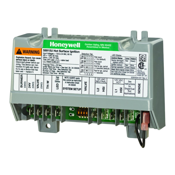
- Página 11 S8910U3000 S8910U HOT SURFACE IGNITER CONTROL Golden Valley, MN 55422 TERMINAL CROSS Assembled in Mexico REFERENCE S8910U Hot Surface Ignition WARNING Selection Tab LED States Input Voltages = 120 & 24 VAC, 60 Hz Trial count S8910U 50E/F47 Control Status Color Pattern HSI = 120V, 5A max.
- Página 12 S8910U3000 TERMINAL CROSS S8910U HOT SURFACE IGNITER CONTROL REFERENCE S8910U HS780 Golden Valley, MN 55422 Assembled in Mexico GND(BURNER) TR (GND CLIP) S8910U Hot Surface Ignition WARNING Selection Tab LED States Input Voltages = 120 & 24 VAC, 60 Hz...
-
Página 13: Startup And Checkout
BOARD AND DISCARD. CONNECT FLAME ROD LEAD WIRE TO SENSE. SEE TABLE 3. CUT QUICK-CONNECTS OFF WIRES AND REPLACE WITH 1/4 IN. QUICK-CONNECTS (PROVIDED). M8530E Fig. 4. Typical hookup when S8910U replaces Honeywell S89/S890. STARTUP AND CHECKOUT 2. Perform a gas leak test, as described in Steps 1... - Página 14 S8910U3000 Step 2: Verify control system ground. f. Turn the thermostat or controller below the room The ignition module must share a common ground with the temperature. Make sure the main burner and the pilot main burner. The burner serves as the common grounding flames go out.
- Página 15 S8910U3000 Purge/Prepurge In either case, the S8910U first initiates a 32-second delay to allow system prepurge. When the S8910U is used in a fan-assisted combustion system, the combustion air blower starts on a call for heat from Igniter Warmup the thermostat. On proof of airflow, the air proving switch closes and energizes the S8910U.
- Página 16 S8910U3000 MAINTENANCE Trial for Ignition At the end of the warmup period, the gas control opens for the ignition trial time determined by the DIP switch configuration. WARNING The hot surface igniter stays powered for an ignition activation period of two seconds if the four second trial time is used or FIRE OR EXPLOSION HAZARD.
-
Página 17: Status Led Used To Troubleshoot
S8910U3000 Ignition System Checks 4. The ignition module cannot be repaired. If it malfunc- tions, replace it. 5. Only trained, experienced service technicians should Step 1: Check igniter wire harness. service hot surface ignition systems. Make sure: 6. After servicing, verify proper system operation. - Página 18 S8910U3000 Table 6. LED codes. Color Flash Code Status Steady Device locked - detected welded gas valve relay. Replace control Intermittent blink Hard lockout - exceeded maximum number of retries Yellow Steady Soft lockout - gas valve failure or 8 consecutive recoverable lockouts: the unit will wait 1 hour before next ignition attempt.
- Página 19 S8910U3000 START TURN THERMOSTAT TO NOTE: BEFORE TROUBLESHOOTING, BECOME FAMILIAR WITH STARTUP CALL FOR HEAT AND CHECKOUT PROCEDURES. • CHECK LINE VOLTAGE POWER. DOES S8910U GET POWER • CHECK LOW VOLTAGE TRANSFORMER. (24 VAC NOMINAL)? • CHECK LIMIT CONTROLLER. •...
-
Página 20: Flame Current Measurement
M31283A Fig. 8. Measuring flame current with micro-ammeter. Automation and Control Solutions Honeywell International Inc. 1985 Douglas Drive North ® U.S. Registered Trademark Golden Valley, MN 55422 © 2015 Honeywell International Inc. 34-00008EFS—01 M.S. 06-15 customer.honeywell.com Printed in United States... -
Página 21: Caractéristiques Électriques
MODULE D'ALLUMAGE PAR INCANDESCENCE UNIVERSEL NOTICE D’INSTALLATION L'installation de ce produit doit être réalisée par un technicien Une liste complète des modules Honeywell et d’autres d'entretien formé et qualifié. marques pouvant être remplacés par le modèle S8910U est fournie dans les Tableaux 1 à 3. - Página 22 écrire ou téléphoner : 1. Au bureau local de vente de produits de combustion et environnementaux Honeywell (dans les pages blanches de l’annuaire). 2. Honeywell Customer Care...
- Página 23 Tableau 1. Correspondances entre le contrôleur White-Rodgers et le modèle S8910U de Honeywell. REMARQUES : Cette liste est fournie pour référence uniquement. Honeywell se réserve le droit d'ajouter ou de supprimer des modèles à tout moment en fonction d'informations nouvelles ou mises à jour.
- Página 24 Tableau 1. Correspondances entre le contrôleur White-Rodgers et le modèle S8910U de Honeywell. (suite) REMARQUES : Cette liste est fournie pour référence uniquement. Honeywell se réserve le droit d'ajouter ou de supprimer des modèles à tout moment en fonction d'informations nouvelles ou mises à jour.
- Página 25 S8910U3000 Tableau 2. Correspondances entre le contrôleur Robertshaw et le modèle S8910U de Honeywell. S8910U Retrait du Détection Temps de Réchauffage Balayage Numéros de cavalier locale (L) ou à verrouillage Essais Prébalayage de l'allumeur entre essais modèle noir distance (R) d’allumage...
- Página 26 S8910U3000 Tableau 3. Correspondances entre le contrôleur Honeywell et le modèle S8910U de Honeywell. S8910U Retrait du Détection Temps de Réchauffage Balayage cavalier locale (L) ou à verrouillage Essais Prébalayage de l'allumeur entre essais Model Numbers noir distance (R) d’allumage S8910U —...
- Página 27 éviter la condensation. Vérifier également le système de Honeywell; contacter le représentant commercial de régulièrement. Il est recommandé d’utiliser un boîtier NEMA 4 Honeywell pour obtenir de l'aide.
-
Página 28: Accumulation De Poussière Ou De Graisse
S8910U3000 sont en suspension dans l'air, comme dans certaines d’appareils tant qu’il n’est pas certain que la applications industrielles ou agricoles, utiliser un boîtier NEMA zone de l’appareil est exempte de gaz. 4 pour le module d'allumage. 3. Ne pas tenter de démonter ou de nettoyer le module. -
Página 29: Câblage Du Module
S8910U3000 Câblage du module MONTER DANS L'UNE DE CES POSITIONS MISE EN GARDE 1. Consulter le schéma de câblage fourni par le fabricant de l'appareil, s'il est disponible, et le comparer au Tableau 5. Suivre attentivement toute directive spéciale concernant les procédures générales mentionnées dans cette section. - Página 30 S8910U3000 Tableau 5. Bornes de câblage de remplacement. Contrôleur de rechange Contrôleur d'origine Borne S89/S890 Borne White Borne Robertshaw Fonction de borne Borne S8910U Honeywell Rodgers 50E/F47 HS780 Raccord de terre du brûleur TERRE (BRÛLEUR) TERRE TERRE TR (CLIP DE (BRÛLEUR)
- Página 31 S8910U3000 CONTRÔLEUR D'ALLUMAGE PAR INCANDESCENCE S8910U CORRESPONDANCES Golden Valley, MN 55422 Assembled in Mexico DES BORNES S8910U Hot Surface Ignition WARNING S8910U 50E/F47 Selection Tab LED States Input Voltages = 120 & 24 VAC, 60 Hz Trial count Control Status Color Pattern HSI = 120V, 5A max.
- Página 32 S8910U3000 CONTRÔLEUR D'ALLUMAGE PAR INCANDESCENCE S8910U CORRESPONDANCES DES BORNES S8910U HS780 Golden Valley, MN 55422 Assembled in Mexico TERRE (BRÛLEUR) TR (CLIP DE TERRE) S8910U Hot Surface Ignition WARNING Selection Tab LED States Input Voltages = 120 & 24 VAC, 60 Hz...
- Página 33 COUPER LES CONNECTEURS RAPIDES DES FILS ET LES REMPLACER PAR LES CONNECTEURS RAPIDES 1/4 PO (FOURNIS). MF8530 Fig. 4. Raccordement typique lorsque le modèle S8910U remplace le modèle Honeywell S89/S890. MISE EN SERVICE ET 2. Réaliser un test de fuite de gaz, tel que décrit dans les étapes 1 et 6 de la section Mise en service et...
- Página 34 S8910U3000 Étape 2 : Vérifier la mise à la terre du système de régulation. Étape 6 : Vérifier que le fonctionnement est normal. Le module d’allumage doit partager une terre commune avec a. Régler le thermostat ou le contrôleur à une température le brûleur principal.
- Página 35 S8910U3000 FONCTIONNEMENT VÉRIFICATION DE L'ÉTAT DE LA FLAMME DU BRÛLEUR Le modèle S8910U est un contrôleur à allumage direct utilisé FLAMME EN SUSPENSION avec un allumeur par incandescence à réchauffage temporisé VÉRIFIER LES POINTS SUIVANTS : BRUYANTE • HAUTE PRESSION DE GAZ de 120 V c.a.
- Página 36 S8910U3000 APPEL DE CHALEUR (BORNE 24 V ACTIVÉE) RELAIS CONTRÔLES DISPOSITIF VERROUILLÉ SOUDÉS D'INITIALISATION (REMPLACER LE CONTRÔLEUR) DÉTECTÉS DÉFAILLANCE INTERBALAYAGE SYSTÈME NE DE SIMULATION PRÉBALAYAGE (32 S) DÉMARRE PAS (64 S) DE FLAMME PAS DE DÉFAILLANCE DE SIMULATION DE FLAMME RÉCHAUFFAGE DE L'ALLUMEUR...
-
Página 37: Arrêt De Sécurité
S8910U3000 du S8910U détecte le courant de flamme et maintient le Il est important de procéder à un entretien préventif régulier sur contrôleur de gaz ouvert. La flamme principale est surveillée les applications plaçant une charge importante sur les en continu durant l’appel de chaleur. - Página 38 S8910U3000 4. Le module d’allumage ne peut pas être réparé. S'il est • Quatre clignotements jaunes indiquent une erreur interne. défaillant, remplacez-le. La cause la plus probable est une défaillance de la logique 5. Seuls des techniciens d’entretien formés et expéri- du S8910U.
- Página 39 S8910U3000 • L'allumeur doit maintenir une résistance d'isolement nécessaire. d'au moins 500 M ohms entre les fils de l'allumeur et • S’assurer que les connexions électriques sont le support de montage de l'allumeur. propres et étanches. Remplacer le fil endommagé...
- Página 40 S8910U3000 DÉMARRAGE METTRE LE THERMOSTAT EN REMARQUE : AVANT DE PROCÉDER AU DÉPANNAGE, SE FAMILIARISER AVEC LES MODE D’APPEL DE CHALEUR PROCÉDURES DE MISE EN SERVICE ET DE VÉRIFICATION. • CONTRÔLER LA TENSION SECTEUR. LE S8910U EST-IL ALIMENTÉ • CONTRÔLER LE TRANSFORMATEUR DE TENSION.
-
Página 41: Mesure Du Courant De Flamme
S8910U3000 Mesure du courant de flamme Le courant de flamme du dispositif peut être mesuré à l’aide Courant de flamme minimum recommandé : • Doit indiquer 1 μAmp CC régulier au minimum. d’un micro-ampèremètre standard en insérant simplement les • Le courant de flamme doit être de 2 μAmp ou plus pour un sondes de l’ampèremètre dans les trous marqués FLAME... - Página 42 S8910U3000 34-00008EFS—01...
- Página 43 S8910U3000 34-00008EFS—01...
- Página 44 S8910U3000 Solutions de régulation et d’automatisation Honeywell International Inc. 1985 Douglas Drive North ® Marque de commerce déposée aux États-Unis © 2015 Honeywell International Inc. Golden Valley, MN 55422 Tous droits réservés 34-00008EFS—01 M.S. 06-15 customer.honeywell.com Imprimé aux États-Unis...
-
Página 45: Módulo Universal De Encendido Por Superficie Caliente
En las tablas 1, 2 y 3, se proporciona una lista completa de los S8910U está diseñado para garantizar el reemplazo sencillo módulos de Honeywell y otras marcas que pueden en el campo de una gran variedad de módulos de encendido reemplazarse por el módulo S8910U. -
Página 46: Información Para Pedidos
1. La Oficina de Ventas de Controles Ambientales y Combustión de Honeywell correspondiente a su localidad (consulte las páginas blancas de su guía telefónica). - Página 47 S8910U3000 Tabla 1. Referencia cruzada de control de White-Rodgers a módulo S8910U de Honeywell. NOTAS: Esta lista es solo para referencia. Honeywell se reserva el derecho de agregar o eliminar modelos en cualquier momento, según información nueva o actualizada. S8910U...
- Página 48 S8910U3000 Tabla 1. Referencia cruzada de control de White-Rodgers a módulo S8910U de Honeywell. (continuación) NOTAS: Esta lista es solo para referencia. Honeywell se reserva el derecho de agregar o eliminar modelos en cualquier momento, según información nueva o actualizada.
- Página 49 S8910U3000 Tabla 2. Referencia cruzada de control de Robertshaw a módulo S8910U de Honeywell. S8910U Calentamiento Retirar Detección Tiempo de Pruebas Números de puente local (L) o bloqueo Prepurga encendedor Purga entre modelo negro remota (R) encendido pruebas (s) Especificaciones —...
-
Página 50: Especificaciones
S8910U3000 Tabla 3. Referencia cruzada del control de Honeywell con el S8910U. S8910U Calentamiento Retirar Detección Tiempo de Pruebas Números de puente local (L) o bloqueo Prepurga encendedor Purga entre modelo negro remota (R) encendido pruebas (s) Especificaciones — Local o... -
Página 51: Revisión De La Instalación
Es necesario que Ingeniería de Control para suficiente para evitar la condensación. No se olvide de Casas y Edificios de Honeywell revise estas aplicaciones. controlar frecuentemente el sistema. Se recomienda utilizar Comuníquese con su representante de ventas de Honeywell una cubierta NEMA 4 para el módulo de encendido. -
Página 52: Instalación
S8910U3000 Acumulación de polvo o grasa 3. No intente desarmar o limpiar el módulo. Si se lo vuelve a armar o se limpia de manera incorrecta, Si se acumula mucho polvo o grasa, es posible que los es posible que su funcionamiento sea inestable. -
Página 53: Cableado Del Módulo
S8910U3000 Cableado del módulo MONTAR EN UNA DE ESTAS POSICIONES PRECAUCIÓN 1. Si el fabricante del artefacto proporciona un diagrama de cableado, consúltelo y compárelo con la tabla 5. Siga con cuidado todas las instrucciones especiales relacionadas con los procedimientos generales que se indican en esta sección. - Página 54 S8910U3000 Tabla 5. Reemplazo de terminales de cableado. Control de reemplazo Control original Terminal de Terminal de Terminal de S89/S890 de 50E/F47 de HS780 de Función del terminal Terminal de S8910U Honeywell White-Rodgers Robertshaw Conexión a tierra del quemador GND (BURNER)
- Página 55 S8910U3000 CONTROL DEL ENCENDEDOR POR SUPERFICIE CALIENTE S8910U REFERENCIA CRUZADA DE LOS TERMINALES Golden Valley, MN 55422 S8910U 50E/F47 Assembled in Mexico S8910U Hot Surface Ignition GND(BURNER) WARNING Selection Tab LED States Input Voltages = 120 & 24 VAC, 60 Hz...
- Página 56 S8910U3000 REFERENCIA CRUZADA CONTROL DEL ENCENDEDOR POR SUPERFICIE CALIENTE S8910U DE LOS TERMINALES S8910U HS780 Golden Valley, MN 55422 Assembled in Mexico GND(BURNER) TR (GND CLIP) S8910U Hot Surface Ignition WARNING Selection Tab LED States Input Voltages = 120 & 24 VAC, 60 Hz...
- Página 57 CONSULTE LA TABLA 3. CORTE LAS CONEXIONES DIRECTAS DEL CONDUCTOR Y REEMPLÁCELAS CON LA CONEXIÓN RÁPIDA DE 1/4 IN (6.3 MM) (SUMINISTRADA). MS8530 Fig. 4. Conexión típica cuando el módulo S8910U reemplaza el modelo S89/S890 de Honeywell. PUESTA EN MARCHA Y ADVERTENCIA VERIFICACIÓN...
- Página 58 S8910U3000 c. Abra las válvulas manuales de corte de la tubería de gas que no se dirija gas hacia el quemador. hacia al artefacto. g. Antes de continuar, ajuste el termostato a una d. Si se realizaron tareas en la tubería, controle que no haya temperatura por debajo de la temperatura ambiente y fugas de gas en dirección ascendente del control de gas.
-
Página 59: Funcionamiento
S8910U3000 FUNCIONAMIENTO REVISE EL ESTADO DE LA LLAMA DEL QUEMADOR El módulo S8910U es un control de encendido directo que se LLAMA ELEVADA utiliza con un encendedor por superficie caliente de 120 V CA CON RUIDO REVISE QUE NO HAYA: con calentamiento temporizado. -
Página 60: Prueba Para Encendido
S8910U3000 ORDEN DE CALEFACCIÓN (SUMINISTRO DE ENERGÍA PARA EL TERMINAL 24V) DETECCIÓN DISPOSITIVO BLOQUEADO CONTROLES DE INICIO DE RELÉS (REEMPLAZAR CONTROL) SOLDADOS FALLA DE EL SISTEMA ENTRE PURGAS SIMULACIÓN PREPURGA (32 S) NO ARRANCA (64 S) DE LLAMA SIMULACIÓN CORRECTA... -
Página 61: Mantenimiento
S8910U3000 (conexión a tierra del quemador). El circuito de detección de Es importante realizar un mantenimiento habitual y preventivo llama del módulo S8910U detecta la corriente de llama y en aplicaciones que signifiquen una gran exigencia para los mantiene abierto el control de gas. La llama principal se controles del sistema, como aquellos utilizados en la industria controla continuamente durante la orden de calefacción. -
Página 62: Led De Estado Para Localización Y Solución De Problemas
S8910U3000 4. El módulo de encendido no se puede reparar. Si fun- Si la señal de la rectificación de llama es fuerte cuando el ciona incorrectamente, debe reemplazarlo. artefacto se enciende, pero se debilita cuando se suministra 5. Solo los técnicos de servicio capacitados y experi-... -
Página 63: Color Código De Destello Rojo Fijo
S8910U3000 c. Controle que la temperatura del aislante de cerámica en siguientes especificaciones: • El encendedor debe alcanzar los 1,832 °F (1,000 °C) el sensor de llama no sea excesiva (por encima de dentro de los 7, 17, 34 o 45 segundos de 1,000 °F [538 °C]). - Página 64 S8910U3000 INICIO ENCIENDA EL TERMOSTATO NOTA: ANTES DE REALIZAR LA TAREA DE LOCALIZACIÓN Y SOLUCIÓN DE PROBLEMAS, PARA QUE EMITA UNA DEBE FAMILIARIZARSE CON LOS PROCEDIMIENTOS DE PUESTA EN MARCHA Y VERIFICACIÓN. ORDEN DE CALEFACCIÓN. • REVISE EL SUMINISTRO DE ENERGÍA DEL VOLTAJE DE LÍNEA.
-
Página 65: Medición De La Corriente De Llama
S8910U3000 Medición de la corriente de llama La corriente de llama de un dispositivo se puede medir con un Corriente de llama mínima recomendada: La lectura debe ser estable, de 1 μA en CC, como mínimo. microamperímetro estándar. Simplemente, se deben insertar •... - Página 66 S8910U3000 34-00008EFS—01...
- Página 67 S8910U3000 34-00008EFS—01...
-
Página 68: Automatización Y Control Desenlace
S8910U3000 Automatización y control desenlace Honeywell International Inc. 1985 Douglas Drive North ® Marca Registrada en los Estados Unidos © 2015 Honeywell International Inc. todos Golden Valley, MN 55422 Los Derechos Reservados 34-00008EFS—01 M.S. 06-15 customer.honeywell.com Impreso en Estados Unidos...