Tabla de contenido
Publicidad
Idiomas disponibles
Idiomas disponibles
Enlaces rápidos
EDK94AZHY26
.8%S
L−force Drives
9400
E94AZHY0026
Motorbremsen−Ansteuerung
Motor Brake Control
Module de pilotage du frein de parking
Control de freno de motor
Modulo di comando freno motore
Montageanleitung
Mounting Instructions
Instructions de montage
Instrucciones para el montaje
Istruzioni per il montaggio
l
Publicidad
Capítulos
Tabla de contenido

Manuales relacionados para Lenze E94AZHY0026


Resumen de contenidos para Lenze E94AZHY0026
- Página 1 L−force Drives .8%S Montageanleitung Mounting Instructions Instructions de montage Instrucciones para el montaje Istruzioni per il montaggio 9400 E94AZHY0026 Motorbremsen−Ansteuerung Motor Brake Control Module de pilotage du frein de parking Control de freno de motor Modulo di comando freno motore...
- Página 2 Lesen Sie zuerst diese Anleitung und die Dokumentation zum Grundgerät, bevor Sie mit den Arbeiten beginnen! Beachten Sie die enthaltenen Sicherheitshinweise. Please read these instructions and the documentation of the standard device before you start working! Observe the safety instructions given therein! Lire le présent fascicule et la documentation relative à...
- Página 3 E94AZHY001...
-
Página 4: Lieferumfang
X107 Anschluss Versorgung und Bremse © 2019 Lenze Automation GmbH, Postfach 10 13 52, 31763 Hameln, Hans−Lenze−Str. 1, 31855 Aerzen Ohne besondere schriftliche Genehmigung von Lenze Automation GmbH darf kein Teil dieser Dokumen- tation vervielfältigt oder Dritten zugänglich gemacht werden. -
Página 5: Tabla De Contenido
Inhalt Sicherheitshinweise ..........Definition der verwendeten Hinweise . - Página 6 Beschreibung 13211684 08/2007 TD15 Erstausgabe .8%S 09/2019 TD15 Korrektur der Beschriftung an Klemme X107 0Abb. 0Tab. 0 Tipp! Aktuelle Dokumentationen und Software−Updates zu Lenze Produkten finden Sie im Internet jeweils im Bereich "Services & Downloads" unter http://www.Lenze.com EDK94AZHY26 DE/EN/FR/ES/IT 1.2...
-
Página 7: Sicherheitshinweise
Sicherheitshinweise Definition der verwendeten Hinweise Sicherheitshinweise Definition der verwendeten Hinweise Um auf Gefahren und wichtige Informationen hinzuweisen, werden in dieser Dokumenta- tion folgende Piktogramme und Signalwörter verwendet: Sicherheitshinweise Aufbau der Sicherheitshinweise: Gefahr! (kennzeichnet die Art und die Schwere der Gefahr) Hinweistext (beschreibt die Gefahr und gibt Hinweise, wie sie vermieden werden kann) Piktogramm und Signalwort... - Página 8 Sicherheitshinweise Definition der verwendeten Hinweise Anwendungshinweise Piktogramm und Signalwort Bedeutung Wichtiger Hinweis für die störungsfreie Funktion Hinweis! Nützlicher Tipp für die einfache Handhabung Tipp! Verweis auf andere Dokumentation Spezielle Sicherheitshinweise und Anwendungshinweise für UL und UR Piktogramm und Signalwort Bedeutung Sicherheitshinweis oder Anwendungshinweis für den Betrieb eines UL−approbierten Geräts in UL−approbierten Anlagen.
-
Página 9: Allgemeine Sicherheits− Und Anwendungshinweise
Sicherheitshinweise Allgemeine Sicherheits− und Anwendungshinweise Allgemeine Sicherheits− und Anwendungshinweise Gefahr! Gefährliche elektrische Spannung! An den Anschlüssen des Bremsenschalters können gefährliche elektrische Spannungen anliegen. Mögliche Folgen: Tod oder schwerste Verletzungen beim Berühren der Anschlussklemmen. ƒ Schutzmaßnahmen: Vor allen Arbeiten das Grundgerät und den Bremsenschalter vom Netz ƒ... -
Página 10: Sicherheitshinweise Für Die Installation Nach Ul Oder Ur
Sicherheitshinweise Sicherheitshinweise für die Installation nach UL oder UR Sicherheitshinweise für die Installation nach U oder U Warnings! Use H, K5 or CC fuses. ƒ Voltage of the fuses must at least be suitable with the input voltage. ƒ Use 60/75 °C wire only. ƒ... -
Página 11: Technische Daten
Technische Daten Allgemeine Daten und Einsatzbedingungen Technische Daten Allgemeine Daten und Einsatzbedingungen Gültigkeit Diese Anleitung ist gültig für ƒ Motorbremsen−Ansteuerung, Typ E94AZHY0026, Version HW: 1A Identifikation E94AZHY002 Typenschlüssel Produktreihe Gerätegeneration Zubehör Typ Motorbremsen−Ansteuerung Bemessungsstrom 002 = 0.75 A 010 = 5.0 A... - Página 12 Technische Daten Allgemeine Daten und Einsatzbedingungen Einsetzbarkeit Diese Komponente ist mit den nachfolgend aufgeführten Produkten einsetzbar. Type E94ASxE032x E94ASxE047x E94ASxE059x ab 1C ab 1.51 E94ASxE086x E94ASxE104x E94ASxE1454 E94ASxE1724 E94ASxE2024 ab 1A ab 1.51 E94ASxE2454 E94ASxE2924 E94ASxE3664 E94ASxE4604 E94ASxE5724 ab 1A ab 1.51 E94ASxE6354 E94ASxE6954...
- Página 13 Technische Daten Allgemeine Daten und Einsatzbedingungen Allgemeine Daten Konformität und Approbation Konformität 73/23/EWG Niederspannungsrichtlinie Approbation UL 508C Industrial Control Equipment Recognized (File No. E132659) für USA Personenschutz und Geräteschutz Schutzart EN 60529 IP00 Schutzmaßnahmen Gegen Kurzschluss Störaussendung EN 61800−3 Leitungsgeführt, Kategorie C2. Störfestigkeit EN 61800−3 Burst auf Netzleitung:...
- Página 14 Technische Daten Allgemeine Daten und Einsatzbedingungen Einsatzbedingungen Umweltbedingungen Klima Lagerung IEC/EN 60721−3−1 1K3 (−25 ... +60 °C) Transport IEC/EN 60721−3−2 2K3 (−25 ... +70 °C) Betrieb IEC/EN 60721−3−3 3K3 (−10 ... +55 °C) Aufstellhöhe 0 ... 4000 m üNN 1000 ... 4000 m üNN: Stromreduzierung 5 %/1000 m Verschmutzung EN 61800−5−1 Verschmutzungsgrad 2...
-
Página 15: Bemessungsdaten
Technische Daten Bemessungsdaten Bemessungsdaten Eingangsdaten Phasen- Spannung Frequenz Strom [A] zahl [Hz] bis +45 °C bis +55 °C E94AZHY0026 400/500 50/60 0.61/0.61 0.61/0.61 Temperatur im Schaltschrank Ausgangsdaten Phasen- Spannung Frequenz Strom [A] zahl [Hz] bis +45 °C bis +55 °C... - Página 16 Technische Daten Bemessungsdaten Zulässige Schalthäufigkeiten Empfohlene Bremse Leistung Spule: Spannung DC 180 V Zulässige Schalthäufigkeit P [W] L [H] I [A] (20 °C) [1/min] BFK457−06E 0,11 BFK458−06E BFK457−08E 0,14 BFK458−08E BFK457−10E 0,17 BFK458−10E BFK457−12E 0,22 BFK458−12E BFK457−14E 0,28 BFK458−14E BFK457−16E 0,31 BFK458−16E BFK457−18E...
-
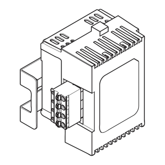
Página 17: Mechanische Installation
Mechanische Installation Mechanische Installation Bei der Installation die Hinweise aus der Dokumentation zum Grundgerät beachten! E94AZHY003 EDK94AZHY26 DE/EN/FR/ES/IT 1.2... - Página 18 Mechanische Installation Montageschritte 1. Motorbremsen−Ansteuerung auf die Klemmen 0 des Grundgerätes stecken. – Beide Klammern 1 müssen in den Nuten 2 des Grundgerätes einrasten! 2. Motorbremsen−Ansteuerungsmodul auf festen Sitz kontrollieren. EDK94AZHY26 DE/EN/FR/ES/IT 1.2...
-
Página 19: Elektrische Installation
ƒ geschirmt ausführen. – Der Betrieb mit ungeschirmten Bremsenleitungen kann die Motorbremsen−Ansteuerung zerstören. – Wir empfehlen die Verwendung von Lenze−Systemleitungen (Motorleitung mit separat geschirmten Zusatzadern). – Schirm beidseitig auf PE legen. Achten Sie bei einer Permanentmagnet−Haltebremse auf korrekte Polung ƒ... -
Página 20: Anschlussdaten
Elektrische Installation Anschlussdaten Anschlussdaten Klemme X107 Beschriftung Beschreibung Anschluss der Motorhaltebremse: + (Lenze: WH) − (Lenze: BN) E94AZHY0026: 180 V DC, max. 0.61 A Auf richtige Polung achten! Versorgungsspannung der Motorhaltebremse L2/N SSP94A6107 Klemmendaten Leiterquerschnitt Anzugsmoment [AWG] [Nm] [lb−in] flexibel 0.5 ... -
Página 21: Verdrahtungsbeispiel
Elektrische Installation Verdrahtungsbeispiel Verdrahtungsbeispiel E94APNExxx4 E94AMxExxx4 E94ASxExxx4 E94AZHY0026 E94AZHY0026 X107 X107 L2/N L2/N L1 " " " " ≤ 2.5 mm² E94AZH016−2 Bei der Auslegung der Sicherung die Normen des Leitungsschutzes beachten! " HF−Schirmabschluss durch großflächige PE−Anbindung. EDK94AZHY26 DE/EN/FR/ES/IT 1.2... - Página 22 X107 Connection of supply and brake © 2019 Lenze Automation GmbH, Postfach 10 13 52, 31763 Hameln, Hans−Lenze−Str. 1, 31855 Aerzen No part of this documentation may be reproduced or made accessible to third parties without written consent by Lenze Automation GmbH.
- Página 23 Contents Safety instructions ..........Definition of notes used .
-
Página 24: Document History
TD15 First edition .8%S 09/2019 TD15 Correction of X107 terminal labelling 0Fig. 0Tab. 0 Tip! Current documentation and software updates concerning Lenze products can be found on the Internet in the "Services & Downloads" area under http://www.Lenze.com EDK94AZHY26 DE/EN/FR/ES/IT 1.2... -
Página 25: Safety Instructions
Safety instructions Definition of notes used Safety instructions Definition of notes used The following pictographs and signal words are used in this documentation to indicate dangers and important information: Safety instructions Structure of safety instructions: Danger! (characterises the type and severity of danger) Note (describes the danger and gives information about how to prevent dangerous situations) -
Página 26: Application Notes
Safety instructions Definition of notes used Application notes Pictograph and signal word Meaning Important note to ensure troublefree operation Note! Useful tip for simple handling Tip! Reference to another documentation Special safety instructions and application notes for UL and UR Pictograph and signal word Meaning Safety or application note for the operation of a... -
Página 27: General Safety And Application Notes
Safety instructions General safety and application notes General safety and application notes Danger! Dangerous electrical voltage! Dangerous electrical voltages may be applied to the connections of the brake switch. Possible consequences: Death or severe injuries when touching the terminals. ƒ Protective measures: Disconnect the standard device and the brake switch from the mains ƒ... -
Página 28: Safety Instructions For The Installation According To Ul Or Ur
Safety instructions Safety instructions for the installation according to UL or UR Safety instructions for the installation according to U or U Warnings! Use H, K5 or CC fuses. ƒ Voltage of the fuses must at least be suitable with the input voltage. ƒ... -
Página 29: Technical Data
Technical data General data and operating conditions Technical data General data and operating conditions Validity These instructions are valid for ƒ Motor brake control, type E94AZHY0026, version HW: 1A Identification E94AZHY002 Type code Product series Version Accessories Motor brake control type Rated current 002 = 0.75 A... - Página 30 Technical data General data and operating conditions Application range This component can be used together with the following products. Type E94ASxE032x E94ASxE047x E94ASxE059x 1C or higher 1.51 or higher E94ASxE086x E94ASxE104x E94ASxE1454 E94ASxE1724 E94ASxE2024 1A or higher 1.51 or higher E94ASxE2454 E94ASxE2924 E94ASxE3664...
- Página 31 Technical data General data and operating conditions General data Conformity and approval Conformity 73/23/EEC Low−Voltage Directive Approval UL 508C Industrial Control Equipment Recognised (file no. E132659) for USA Protection of persons and equipment Enclosure EN 60529 IP00 Protective measures Against short circuit Noise emission EN 61800−3 Conducted, category C2.
- Página 32 Technical data General data and operating conditions Operating conditions Environmental conditions Climate Storage IEC/EN 60721−3−1 1K3 (−25 ... +60 °C) Transport IEC/EN 60721−3−2 2K3 (−25 ... +70 °C) Operation IEC/EN 60721−3−3 3K3 (−10 ... +55 °C) Site altitude 0 ... 4000 m amsl 1000 ...
-
Página 33: Rated Data
Rated data Input data Number Voltage Frequency Current [A] Type [Hz] max. +45 °C max. +55 °C phases E94AZHY0026 400/500 50/60 0.61/0.61 0.61/0.61 Temperature in the control cabinet Output data Number Voltage Frequency Current [A] Type [Hz] max. - Página 34 Technical data Rated data Permissible operating frequencies Recommended brake Power Coil: Voltage DC 180 V Permissible operating frequency Type P [W] L [H] I [A] (20 °C) [rpm] BFK457−06E 0.11 BFK458−06E BFK457−08E 0.14 BFK458−08E BFK457−10E 0.17 BFK458−10E BFK457−12E 0.22 BFK458−12E BFK457−14E 0.28 BFK458−14E...
-
Página 35: Mechanical Installation
Mechanical installation Mechanical installation During installation the notes given in the documentation for the standard device must be observed! E94AZHY003 EDK94AZHY26 DE/EN/FR/ES/IT 1.2... - Página 36 Mechanical installation Installation steps 1. Plug the motor brake control module onto the terminals 0 of the standard device. – Ensure that both clips 1 snap into the slots 2 of the standard device! 2. Check that the motor brake control module is securely connected. EDK94AZHY26 DE/EN/FR/ES/IT 1.2...
-
Página 37: Electrical Installation
ƒ – An operation with unshielded brake cables can destroy the motor brake control module. – We recommend the use of Lenze system cables (motor cable with separately shielded additional cores). – Connect the shield to PE on both sides. -
Página 38: Connection Data
Connection data Terminal X107 Labelling Description Connection of the motor holding brake: + (Lenze: WH) − (Lenze: BN) E94AZHY0026: 180 V DC, max. 0.61 A Ensure correct polarity! Supply voltage of the motor holding brake L2/N SSP94A6107 Terminal data Conductor cross−section... -
Página 39: Wiring Example
Electrical installation Wiring example Wiring example E94APNExxx4 E94AMxExxx4 E94ASxExxx4 E94AZHY0026 E94AZHY0026 X107 X107 L2/N L2/N L1 " " " " ≤ 2.5 mm² E94AZH016−2 Observe the cable protection standards for fuse dimensioning! " HF shield termination through large−surface PE connection... -
Página 40: Équipement Livré
X107 Raccordement de l’alimentation et du frein © 2019 Lenze Automation GmbH, Postfach 10 13 52, 31763 Hameln, Hans−Lenze−Str. 1, 31855 Aerzen Toute représentation ou reproduction, en tout ou en partie et par quelque procédé que ce soit, est illicite sans l’autorisation écrite préalable de Lenze Automation GmbH. - Página 41 Sommaire Consignes de sécurité ..........Définition des conventions utilisées .
-
Página 42: Historique Du Document
Correction de l’inscription sur le bornier X107 0Fig. 0Tab. 0 Conseil ! Les mises à jour de logiciels et les documentations récentes relatives aux produits Lenze sont disponibles dans la zone "Téléchargements" du site Internet : http://www.Lenze.com EDK94AZHY26 DE/EN/FR/ES/IT 1.2... -
Página 43: Consignes De Sécurité
Consignes de sécurité Définition des conventions utilisées Consignes de sécurité Définition des conventions utilisées Pour indiquer des risques et des informations importantes, la présente documentation utilise les mots et pictogrammes suivants : Consignes de sécurité Présentation des consignes de sécurité Danger ! (Le pictogramme indique le type de risque.) Explication... -
Página 44: Consignes D'uTilisation
Consignes de sécurité Définition des conventions utilisées Consignes d’utilisation Pictogramme et mot associé Explication Remarque Remarque importante pour assurer un fonctionnement correct importante ! Conseil utile pour faciliter la mise en œuvre Conseil ! Renvoi à une autre documentation Consignes de sécurité et d’utilisation spécifiques selon UL et UR Pictogramme et mot associé... -
Página 45: Instructions Générales De Sécurité Et D'uTilisation
Consignes de sécurité Instructions générales de sécurité et d’utilisation Instructions générales de sécurité et d’utilisation Danger ! Tension électrique dangereuse ! Des tensions électriques dangereuses peuvent circuler dans les raccordements du contacteur de frein. Risques encourus : Mort ou blessures très graves en cas de contact accidentel avec les bornes ƒ... -
Página 46: Consignes De Sécurité Pour L'iNstallation Selon Ul Ou Ur
Consignes de sécurité Consignes de sécurité pour l’installation selon UL ou UR Consignes de sécurité pour l’installation selon U ou U Warnings ! Use H, K5 or CC fuses. ƒ Voltage of the fuses must at least be suitable with the input voltage. ƒ... -
Página 47: Spécifications Techniques
Caractéristiques générales et conditions d’utilisation Spécifications techniques Caractéristiques générales et conditions d’utilisation Validité Le présent document s’applique au produits suivants : ƒ aux modules de pilotage du frein de parking, type E94AZHY0026, version matérielle : 1A Identification E94AZHY002 Codification des types Série d’appareils... - Página 48 Spécifications techniques Caractéristiques générales et conditions d’utilisation Utilisation Ces composants peuvent être utilisés avec les produits indiqués ci−dessous. Type E94ASxE032x E94ASxE047x E94ASxE059x A partir de 1C A partir de 1.51 E94ASxE086x E94ASxE104x E94ASxE1454 E94ASxE1724 E94ASxE2024 A partir de 1A A partir de 1.51 E94ASxE2454 E94ASxE2924 E94ASxE3664...
- Página 49 Spécifications techniques Caractéristiques générales et conditions d’utilisation Caractéristiques générales Conformité et homologation Conformité 73/23/CEE Directive Basse Tension Homologation UL 508C Industrial Control Equipment Recognised (File No. E132659) pour les Etas−Unis Protection des personnes et protection de l’appareil Indice de protection EN 60529 IP00 Mesures de protection...
- Página 50 Spécifications techniques Caractéristiques générales et conditions d’utilisation Conditions d’utilisation Conditions climatiques Température ambiante Stockage CEI/EN 60721−3−1 Classe 1K3 (−25 ... +60 °C) Transport CEI/EN 60721−3−2 Classe 2K3 (−25 ... +70 °C) Fonctionnement CEI/EN 60721−3−3 Classe 3K3 (−10 ... +55 °C) Altitude d’implantation 0 ...
-
Página 51: Caractéristiques Assignées
Caractéristiques assignées Données d’entrée Nombre Tension Fréquence Courant [A] Type [Hz] +45 °C max. +55 °C max. phases E94AZHY0026 400/500 50/60 0.61/0.61 0.61/0.61 Température dans l’armoire électrique Données de sortie Nombre Tension Fréquence Courant [A] Type [Hz] +45 °C max. - Página 52 Spécifications techniques Caractéristiques assignées Fréquences de manoeuvre admissibles Frein recommandé Puissance Bobine : tension 180 V CC Fréquence de manoeuvre admissible Type P [W] L [H] I [A] (20 °C) [1/min] BFK457−06E 0.11 BFK458−06E BFK457−08E 0.14 BFK458−08E BFK457−10E 0.17 BFK458−10E BFK457−12E 0.22 BFK458−12E...
-
Página 53: Installation Mécanique
Installation mécanique Installation mécanique Lors de l’installation, tenir compte des indications contenues dans la documentation de l’appareil de base ! E94AZHY003 EDK94AZHY26 DE/EN/FR/ES/IT 1.2... - Página 54 Installation mécanique Procéder aux opérations de montage suivantes : 1. Enficher le module de pilotage du frein de parking dans les bornes 0de l’appareil de base. – Veiller à ce que les deux griffes 1 soient insérées dans les rainures 2 de l’appareil de base ! 2.
-
Página 55: Installation Électrique
– L’utilisation de câbles de frein non blindés risque de détruire le module de pilotage du frein de parking. – Nous recommandons d’utiliser des câbles système Lenze (câble moteur avec fils supplémentaires blindés séparément). – Raccorder le blindage aux deux extrémités sur PE. -
Página 56: Données De Raccordement
Libellé Description Raccordement du frein de parking : + (Lenze : WH) − (Lenze : BN) E94AZHY0026 : 180 V CC, 0.61 A max. Veiller à une polarisation correcte ! Tension d’alimentation du frein de parking L2/N SSP94A6107 Spécifications des Section de câble... -
Página 57: Exemple De Câblage
Installation électrique Exemple de câblage Exemple de câblage E94APNExxx4 E94AMxExxx4 E94ASxExxx4 E94AZHY0026 E94AZHY0026 X107 X107 L2/N L2/N L1 " " " " ≤ 2.5 mm² E94AZH016−2 Lors du dimensionnement du fusible, respecter les normes concernant la protection des câbles ! "... -
Página 58: Contenido Del Suministro
X107 Conexión alimentación del freno © 2019 Lenze Automation GmbH, Postfach 10 13 52, 31763 Hameln, Hans−Lenze−Str. 1, 31855 Aerzen No está permitido reproducir o poner a disposición de terceros ninguna parte de esta documentación sin la autorización explícita por escrito de Lenze Automation GmbH. - Página 59 Contenido Instrucciones de seguridad ......... . . Definición de las instrucciones utilizadas .
-
Página 60: Histórico Del Documento
TD15 Corrección de la rotulación del borne X107 0Fig. 0Tab. 0 ¡Sugerencia! Encontrará documentación actualizada y actualizaciones de software para los productos Lenze en Internet, en la sección de "Servicios y descargas" de la página web http://www.Lenze.com EDK94AZHY26 DE/EN/FR/ES/IT 1.2... -
Página 61: Instrucciones De Seguridad
Instrucciones de seguridad Definición de las instrucciones utilizadas Instrucciones de seguridad Definición de las instrucciones utilizadas Para indicar peligros e información importante, se utilizan en esta documentación los siguientes términos indicativos y símbolos: Instrucciones de seguridad Estructura de las instrucciones de seguridad: ¡Peligro! (indican el tipo y la gravedad del peligro) Texto indicativo... - Página 62 Instrucciones de seguridad Definición de las instrucciones utilizadas Instrucciones de seguridad y de uso especiales para UL y UR Pictograma y término indicativo Significado Instrucción de seguridad o de uso para la utilización de un equipo con aprobación UL en instalaciones con aprobación UL.
-
Página 63: Instrucciones Generales De Seguridad Y De Uso
Instrucciones de seguridad Instrucciones generales de seguridad y de uso Instrucciones generales de seguridad y de uso ¡Peligro! ¡Voltaje eléctrico peligroso! En las conexiones del interruptor del freno pueden generarse voltajes eléctricos peligrosos. Posibles consecuencias: Muerte o lesiones muy serias al tocar los bornes de conexión. ƒ... -
Página 64: Instrucciones De Seguridad Para La Instalación Según Ul O Ur
Instrucciones de seguridad Instrucciones de seguridad para la instalación según UL o UR Instrucciones de seguridad para la instalación según U Warnings ! Use H, K5 or CC fuses. ƒ Voltage of the fuses must at least be suitable with the input voltage. ƒ... -
Página 65: Datos Técnicos
Datos generales y condiciones de uso Datos técnicos Datos generales y condiciones de uso Validez Este manual es de aplicación para ƒ Control de freno de motor, tipo E94AZHY0026, versión HW: 1A Identificación E94AZHY002 Código de tipo Serie de productos Generación de equipos... - Página 66 Datos técnicos Datos generales y condiciones de uso Posibilidades de uso Este componente se puede utilizar con los productos que se indican a continuación. Type E94ASxE032x E94ASxE047x E94ASxE059x ab 1C a partir de 1.51 E94ASxE086x E94ASxE104x E94ASxE1454 E94ASxE1724 E94ASxE2024 a partir de 1A a partir de 1.51 E94ASxE2454 E94ASxE2924...
- Página 67 Datos técnicos Datos generales y condiciones de uso Datos generales Conformidad y aprobación Conformidad 73/23/CEE Directiva de bajo voltaje Aprobación UL 508C Industrial Control Equipment Recognised (File No. E132659) para los EE.UU. Protección personal y de equipos Tipo de protección EN 60529 IP00 Medidas de protección...
- Página 68 Datos técnicos Datos generales y condiciones de uso Condiciones de uso Condiciones ambientales Climatología Almacenaje IEC/EN 60721−3−1 1K3 (−25 ... +60 °C) Transporte IEC/EN 60721−3−2 2K3 (−25 ... +70 °C) Funcionamiento IEC/EN 60721−3−3 3K3 (−10 ... +55 °C) Altura de montaje 0 ...
-
Página 69: Datos Nominales
Datos de entrada Número Voltaje Frecuencia Corriente [A] de fases Tipo [Hz] máx. +45 °C máx. +55 °C E94AZHY0026 400/500 50/60 0.61/0.61 0.61/0.61 Temperatura en el armario eléctrico Datos de salida Número Voltaje Frecuencia Corriente [A] de fases... - Página 70 Datos técnicos Datos nominales Frecuencias de conexión admitidas Freno recomendado Potencia Bobina: voltaje DC 180 V Frecuencia de conexión admitida Tipo P [W] L [H] I [A] (20 °C) [1/min] BFK457−06E 0,11 BFK458−06E BFK457−08E 0,14 BFK458−08E BFK457−10E 0,17 BFK458−10E BFK457−12E 0,22 BFK458−12E BFK457−14E...
-
Página 71: Instalación Mecánica
Instalación mecánica Instalación mecánica ¡Durante la instalación se han de tener en cuenta las indicaciones de la documentación correspondiente al equipo básico! E94AZHY003 EDK94AZHY26 DE/EN/FR/ES/IT 1.2... - Página 72 Instalación mecánica Pasos para el montaje 1. Insertar el control del freno de motor en los bornes 0 del equipo básico. – Ambas grapas 1 han de coincidir con las ranuras 2 del equipo básico. 2. Controlar que el módulo de control de freno de motor esté correctamente colocado. EDK94AZHY26 DE/EN/FR/ES/IT 1.2...
-
Página 73: Instalación Eléctrica
– La operación con cables sin apantallar podría destruir el control del freno de motor. – Recomendamos el uso de cables de sistema Lenze (cable de motor con conductores adicionales apantallados por separado). – Colocar malla a ambos lados de PE. -
Página 74: Datos De Conexión
Borne X107 Marcación Descripción Conexión del freno de motor: + (Lenze: WH) − (Lenze: BN) E94AZHY0026: 180 V DC, máx. 0.61 A ¡Observar polarización correcta! Voltaje de alimentación del freno de motor L2/N SSP94A6107 Datos de los Sección de cable... -
Página 75: Ejemplo De Cableado
Instalación eléctrica Ejemplo de cableado Ejemplo de cableado E94APNExxx4 E94AMxExxx4 E94ASxExxx4 E94AZHY0026 E94AZHY0026 X107 X107 L2/N L2/N L1 " " " " ≤ 2.5 mm² E94AZH016−2 ¡Para el dimensionado del fusible tener siempre en cuenta las normas para la protección de cables! "... -
Página 76: Oggetto Della Fornitura
X107 Collegamento alimentazione e freno © 2019 Lenze Automation GmbH, Postfach 10 13 52, 31763 Hameln, Hans−Lenze−Str. 1, 31855 Aerzen Non è consentito riprodurre o distribuire a terzi alcuna parte del presente documento senza il permesso scritto di Lenze Automation GmbH. - Página 77 Sommario Informazioni sulla sicurezza ......... . Simbologia delle note e avvertenze utilizzate .
-
Página 78: Cronologia Del Documento
Prima edizione .8%S 09/2019 TD15 Correzione della siglatura sulla morsettiera X107 0Fig. 0Tab. 0 Suggerimento: La documentazione tecnica e gli aggiornamenti software dei prodotti Lenze sono disponibili in Internet nella sezione "Services & Downloads" del sito http://www.Lenze.com EDK94AZHY26 DE/EN/FR/ES/IT 1.2... -
Página 79: Informazioni Sulla Sicurezza
Informazioni sulla sicurezza Simbologia delle note e avvertenze utilizzate Informazioni sulla sicurezza Simbologia delle note e avvertenze utilizzate Per segnalare pericoli ed informazioni importanti, nella presente documentazione sono riportati i seguenti simboli e parole di segnalazione: Note di sicurezza Struttura delle note di sicurezza: Pericolo! (indica il tipo e la gravità... - Página 80 Informazioni sulla sicurezza Simbologia delle note e avvertenze utilizzate Note di sicurezza e istruzioni d’uso speciali per UL e UR Simbolo e parola di segnalazione Significato Nota di sicurezza o istruzioni d’uso per il funzionamento di un dispositivo con omologazione UL in impianti omologati UL.
-
Página 81: Note Generali Di Sicurezza E Utilizzo
Informazioni sulla sicurezza Note generali di sicurezza e utilizzo Note generali di sicurezza e utilizzo Pericolo! Tensione elettrica pericolosa! Vicino ai collegamenti dell’interruttore del freno possono trovarsi tensioni elettriche pericolose. Possibili conseguenze: Morte o gravi lesioni toccando i morsetti di collegamento. ƒ... -
Página 82: Informazioni Sulla Sicurezza Per L'iNstallazione Secondo Ul O Ur
Informazioni sulla sicurezza Informazioni sulla sicurezza per l’installazione secondo UL o UR Informazioni sulla sicurezza per l’installazione secondo U Warnings ! Use H, K5 or CC fuses. ƒ Voltage of the fuses must at least be suitable with the input voltage. ƒ... -
Página 83: Dati Tecnici
Dati tecnici Dati generali/Condizioni di utilizzo Dati tecnici Dati generali/Condizioni di utilizzo Validità La presente documentazione è valida per ƒ Comando freno motore, tipo E94AZHY0026, versione HW: 1A Identificazione E94AZHY002 Codice di identificazione Serie prodotto Versione Accessorio Tipo modulo di comando freno motore Corrente nominale 002 = 0.75 A... - Página 84 Dati tecnici Dati generali/Condizioni di utilizzo Compatibilità Questo componente può essere utilizzato con i seguenti prodotti. Type E94ASxE032x E94ASxE047x E94ASxE059x ab 1C ab 1.51 E94ASxE086x E94ASxE104x E94ASxE1454 E94ASxE1724 E94ASxE2024 ab 1A ab 1.51 E94ASxE2454 E94ASxE2924 E94ASxE3664 E94ASxE4604 E94ASxE5724 ab 1A ab 1.51 E94ASxE6354 E94ASxE6954...
- Página 85 Dati tecnici Dati generali/Condizioni di utilizzo Dati generali Conformità e omologazioni Conformità 73/23/CE Direttiva Bassa Tensione Omologazione UL 508C Industrial Control Equipment Recognised (File n. E132659) per gli USA Protezione delle persone e protezione del dispositivo Tipo protezione EN 60529 IP00 Misure di protezione contro cortocircuito...
- Página 86 Dati tecnici Dati generali/Condizioni di utilizzo Condizioni di utilizzo Condizioni ambientali Clima Stoccaggio IEC/EN 60721−3−1 1K3 (−25 ... +60 °C) Trasporto IEC/EN 60721−3−2 2K3 (−25 ... +70 °C) Funzionamento IEC/EN 60721−3−3 3K3 (−10 ... +55 °C) Altitudine di 0 ... 4000 m s.l.m. installazione 1000 ...
-
Página 87: Dati Nominali
Dati nominali Dati in ingresso Numero Tensione Frequenza Corrente [A] di fasi Tipo [Hz] max. +45 °C max. +55 °C E94AZHY0026 400/500 50/60 0.61/0.61 0.61/0.61 Temperatura armadio elettrico Dati in uscita Numero Tensione Frequenza Corrente [A] di fasi... - Página 88 Dati tecnici Dati nominali Frequenze di commutazione ammissibili Freno consigliato Potenza Bobina: tensione DC 180 V Frequenza di commutazione ammissibile Tipo P [W] L [H] I [A] (20 °C) [1/min] BFK457−06E 0,11 BFK458−06E BFK457−08E 0,14 BFK458−08E BFK457−10E 0,17 BFK458−10E BFK457−12E 0,22 BFK458−12E BFK457−14E...
-
Página 89: Installazione Meccanica
Installazione meccanica Installazione meccanica Durante l’installazione, osservare le istruzioni fornite nella documentazione del modulo asse. E94AZHY003 EDK94AZHY26 DE/EN/FR/ES/IT 1.2... - Página 90 Installazione meccanica Procedura di montaggio 1. Inserire il modulo di comando del freno motore nei morsetti 0 del modulo asse. – Entrambi i dispositivi di fissaggio 1 devono scattare in posizione nelle apposite scanalature 2 del modulo asse. 2. Verificare che il modulo di comando del freno motore sia correttamente montato. EDK94AZHY26 DE/EN/FR/ES/IT 1.2...
-
Página 91: Installazione Elettrica
– Il funzionamento con cavi freno non schermati può causare la distruzione del modulo di comando freno motore. – Si raccomanda di utilizzare cavi di sistema Lenze (cavo motore con conduttori aggiuntivi schermati separatamente). – Applicare la schermatura a PE su entrambi i lati. -
Página 92: Dati Di Collegamento
Dati di collegamento Morsettiera X107 Siglatura Descrizione Collegamento del freno di stazionamento motore: + (Lenze: WH) − (Lenze: BN) E94AZHY0026: 180 V DC, max. 0.61 A Fare attenzione alla polarità! Tensione di alimentazione del freno di stazionamento motore L2/N SSP94A6107 Dati morsetti... -
Página 93: Esempio Di Cablaggio
Installazione elettrica Esempio di cablaggio Esempio di cablaggio E94APNExxx4 E94AMxExxx4 E94ASxExxx4 E94AZHY0026 E94AZHY0026 X107 X107 L2/N L2/N L1 " " " " ≤ 2.5 mm² E94AZH016−2 Per la selezione del fusibile, osservare le norme relative alla protezione del cavo. "... - Página 94 © 09/2019 Lenze Automation GmbH Service Lenze Service GmbH Postfach 10 13 52, 31763 Hameln Breslauer Straße 3, 32699 Extertal Hans−Lenze−Str. 1, 31855 Aerzen GERMANY GERMANY HR Hannover B 205381 +49 5154 82−0 008000 2446877 (24 h helpline) Ê Ê...