Publicidad
Enlaces rápidos
Installation Manual
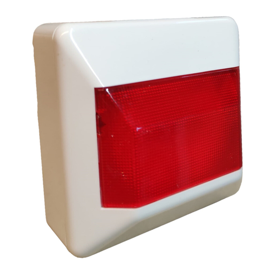
Front view of LED Indicator.
2
3
Analogue;
Negative;
Conventional.
D
ESCRIPTION
Remote LED indicators are ideal for use when an installed
detector is out of view or installed in an enclosed area where alarm
indication is required externally.
The unit uses three LED diodes to provide reduced consumption
illumination.
I
NSTALLATION
This product is part of a fire detection and alarm
system. Ensure that all local regulations are followed
with regard its installation.
Note:
If the product is not connected to a GE-Interlogix detector or if
the product is used for any purpose other than that indicated,
ensure that all voltage and current specifications remain inside
the specified limits (see technical specifications).
The unit should be installed in an area of high visibility to
ensure rapid reaction by fire security personnel.
See your fire detector manual for electrical connection guidelines.
The LED indicator is supplied with a surface-mounting fixture with
entry points on either side for 20 mm tubing. For recessed
mounting a standard recessed mounting box could be used.
The unit may be connected to analogue or conventional fire
systems using the appropriate terminal (see figure
conventional systems / systems of low power consumption only a
single LED will be lit. See Technical Specifications for power
supply details.
M
AINTENANCE
Maintenance of the remote LED indicator will depend on the
environment in which it is installed. In clean areas it may be limited
to periodic functional tests by activating the detector to which it is
connected.
Faults must be repaired by qualified personnel only.
T
S
ECHNICAL
PECIFICATIONS
Power supply (analogue) .....................................................5 to 10 V
© 2003 GE Interlogix B.V.. All rights reserved.
Version 2.4 / August 2004
55302507
1
Electrical connections:
). In
PA25/3L Remote LED Indicator
Power supply (conventional) ..................................................2 to 5 V
Maximum consumption ............................................................50 mA
Maximum distance between LED indicator and detector ......... 100 m
LEDs................................................................................................. 3
Operating temperature ...............................................-10 °C to 60 °C
Storage temperature ..................................................-10 °C to 70 °C
Dimensions.............................................................. 80 x 80 x 42 mm
IP Protection................................................................................IP40
Manual de Instalación
LED Indicador.
Conexiones electricónicos:
3
Negativo;
Convencional.
D
ESCRIPCIÓN
El piloto de acción es idóneo para aquellos casos donde el
detector de incendio está escondido o en locales cerrados,
necesitando repetir la señal de alarma al exterior.
Emplea tres diodos LED para una iluminación de consumo
reducido.
I
NSTALLACIÓN
Este piloto está pensado para formar parte de
sistemas de detección y alarma de incendios.
Aconsejamos
establecidas en la norma UNE 23-007 parte 14.
Nota:
Si no se conecta a un detector de incendio de GE Interlogix, o
si se utiliza este piloto para un uso distinto del indicado, hay
que asegurarse previamente que la tensión y la corriente de
alimentación quedan dentro de los márgenes indicados.
El piloto se instalará siempre en un punto visible que garantice
la rápida comprobación de su estado por el personal de
vigilancia.
Para el conexionado al detector de incendio consultar las
instrucciones del mismo.
El piloto de acción se suministra con un cajetín de superficie con
dos entradas laterales para tubo visto de 20 mm de diámetro. Para
montaje empotrado se deberá adquirir un cajetín estándar de
empotrar con paso entre tornillos de 60 mm y profundidad mínima
de 25 mm.
Installation Manual
1
Analógico;
seguir
las
recomen-daciones
2
Publicidad

Resumen de contenidos para GE PA25/3L
- Página 1 The unit may be connected to analogue or conventional fire Si no se conecta a un detector de incendio de GE Interlogix, o systems using the appropriate terminal (see figure ). In...
- Página 2 Consigliamo di seguire le raccomandazioni stabilite e riportate nella norma UNE 23-007 parte14. Note: Se il prodotto non viene utilizzato con rivelatori GE-Interlogix o se si utilizza il prodotto per un uso diverso da quello precedentemente descritto, verificare e controllare che la tensione e la corrente di alimentazione rimangano entro i limiti indicati (vedere le specifiche tecniche).


