Lenze L-force 9400 Instrucciones Para El Montaje
Ocultar thumbs
Ver también para L-force 9400:
- Instrucciones para el montaje (218 páginas) ,
- Manual de comunicaciones (126 páginas) ,
- Instructions de montage (114 páginas)
Tabla de contenido
Publicidad
Idiomas disponibles
Idiomas disponibles
Enlaces rápidos
Publicidad
Tabla de contenido

Manuales relacionados para Lenze L-force 9400


Resumen de contenidos para Lenze L-force 9400
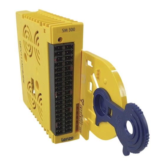
- Página 1 L-force Drives EDK94AYAD ..øp Montageanleitung Mounting Instructions Instructions de montage Instrucciones para el montaje Istruzioni per il montaggio 9400 E94AYAD - SM300 Sicherheitsmodul Safety module Module de sécurité Módulo de seguridad Modulo di sicurezza ...
- Página 2 Lesen Sie zuerst diese Anleitung und die Dokumentation zum Grundgerät, bevor Sie mit den Arbeiten beginnen! Beachten Sie die enthaltenen Sicherheitshinweise. Please read these instructions and the documentation of the standard device before you start working! Observe the safety instructions given therein! ...
- Página 3 SSP94SM317...
-
Página 4: Lieferumfang
Lieferumfang Pos. Beschreibung Sicherheitsmodul SM300, Typ E94AYAD Montageanleitung Elemente auf der Vorderseite Pos. Beschreibung PROFIsafe-Zieladressschalter (in der linken Gehäuseseite) X82.1 X82.2 steckbare Klemmleisten für Ein- und Ausgangssignale X82.3 X82.4 EDK94AYAD DE/EN/FR/ES/IT 2.0... - Página 5 Anzeigen Pos. Farbe Zustand Beschreibung Integrierte Sicherheitstechnik ist fehlerfrei initialisiert. Integrierte Sicherheitstechnik ist fehlerfrei initialisiert. blinkt Die interne Kommunikation zum Grundgerät ist nicht grün möglich. Integrierte Sicherheitstechnik ist nicht initialisiert. Es ist keine Bestätigung möglich. Regler freigegeben gelb Nicht sichere Anzeige ”STO” Systemfehler: Nach schwerem internem Fehler wird STO ausge- löst.
- Página 6 Identifikation ‚ ƒ „ E94YCEI003C E94AYXX001 Produktreihe Gerätegeneration Modulkennung: Gerätemodul Modultyp: Sicherheitsmodul Ausführung A = SM0 B = SM100 D = SM300 E = SM301 Hardwarestand Softwarestand (nur SM30x) Seriennummer EDK94AYAD DE/EN/FR/ES/IT 2.0...
- Página 7 Gültigkeit Diese Anleitung ist gültig für ƒ Sicherheitsmodul E94AYAD - SM300 ab der Typenschildbezeichnung Type E94AYAD 1.00 Einsetzbarkeit Dieses Zubehör darf nur verwendet werden mit ƒ Achsmodul E94AxxExxxx ƒ Kommunikationsmodul PROFIBUS E94AYCPM ab der Typenschildbezeichnung Type E94AxxExxxx 1.10 E94AYCPM 0Abb. 0Tab. 0 ...
-
Página 8: Sicherheitshinweise
Sicherheitshinweise Definition der verwendeten Hinweise Sicherheitshinweise Definition der verwendeten Hinweise Um auf Gefahren und wichtige Informationen hinzuweisen, werden in dieser Dokumenta- tion folgende Piktogramme und Signalwörter verwendet: Sicherheitshinweise Aufbau der Sicherheitshinweise: Gefahr! (kennzeichnet die Art und die Schwere der Gefahr) Hinweistext (beschreibt die Gefahr und gibt Hinweise, wie sie vermieden werden kann) Piktogramm und Signalwort... - Página 9 Sicherheitshinweise Definition der verwendeten Hinweise Spezielle Sicherheitshinweise und Anwendungshinweise für UL und UR Piktogramm und Signalwort Bedeutung Sicherheitshinweis oder Anwendungshinweis für den Betrieb eines UL-approbierten Geräts in UL-approbierten Anlagen. Warnings! Möglicherweise wird das Antriebssystem nicht UL-gerecht betrie- ben, wenn nicht die entsprechenden Maßnahmen getroffen werden.
-
Página 10: Allgemeine Sicherheitshinweise
Sicherheitshinweise Allgemeine Sicherheitshinweise Allgemeine Sicherheitshinweise Beachten Sie unbedingt die folgenden Sicherheitshinweise und Anwendungshinweise, um die zertifizierten Eigenschaften der Sicherheitstechnik zu erhalten und den störungsfreien und gefahrlosen Betrieb zu gewährleisten. Gefahr! Unsachgemäßer Umgang mit dem Modul und dem Grundgerät kann schwere Personenschäden und Sachschäden verursachen. - Página 11 Sicherheitshinweise Allgemeine Sicherheitshinweise Gefahr! Lebensgefahr durch unsachgemäße Installation Unsachgemäße Installation der Sicherheitstechnik kann zu unkontrolliertem Anlaufen der Antriebe führen. Mögliche Folgen: Tod oder schwere Verletzungen ƒ Schutzmaßnahmen: Gesamt-Leitungslänge zwischen X82 und den daran angeschlossenen Komponenten (z. B. Sensoren, Geräte, ...) > 3 m: Die Leitung zwischen X82 und den daran angeschlossenen Komponenten ƒ...
- Página 12 Sicherheitshinweise Sicherheitshinweise für die Installation nach UL oder UR Sicherheitshinweise für die Installation nach U oder U Warnings! Maximum surrounding air temperature: 55 °C. ƒ External fuse for 24 Vdc supply voltage. Rated 4 A DC fuse UL248-14. ƒ ...
-
Página 13: Technische Daten
Technische Daten Technische Daten Funktionen ƒ Sicher abgeschaltetes Moment (STO) (bisher: Sicherer Halt, Schutz gegen unerwarteten Anlauf) ƒ Sicherer Stop 1 (SS1) ƒ Anschluss von Sicherheitssensoren ƒ PROFIsafe Sicherheitsbus Anbindung Versorgung ƒ externe Versorgung durch ein sicher getrenntes Netzteil (SELV/PELV) Grundlage der Daten Netz Nennspannung U... -
Página 14: Mechanische Installation
Mechanische Installation Montage Mechanische Installation Montage E94AYAX001 EDK94AYAD DE/EN/FR/ES/IT 2.0... - Página 15 Mechanische Installation Demontage Demontage E94AYCXX001H EDK94AYAD DE/EN/FR/ES/IT 2.0...
-
Página 16: Elektrische Installation
Elektrische Installation Adressierung Elektrische Installation Hinweis! Bei der Installation die Dokumentation des Antriebsreglers beachten. Adressierung Damit ein Datentelegramm den richtigen Teilnehmer erreicht, ist eine eindeutige PROFIsa- fe-Zieladresse erforderlich. Beschriftung DIP-Schalter Wertigkeit des Adressbits Hinweis! Die Kombination ”Sicherheitsmodul SM300 ab Version VA 1.08 und Kommunikationsmodul PROFIBUS ab Version VB 0.93”... - Página 17 Elektrische Installation Schaltungsbeispiel Schaltungsbeispiel SM300 E94AYAD X82.1 X82.2 24 V ext. X82.3 X82.4 SSP94SM350 E94AYAD Sicherheitsmodul SM300, Version VA1.xx passiver Sensor mit Kanal A und B aktiver Sensor (Lichtgitter) 24 V ext. 24-V-Spannungsversorgung (SELV/PELV) EDK94AYAD DE/EN/FR/ES/IT 2.0...
- Página 18 Elektrische Installation Anschlussdaten Anschlussdaten X82.1 Beschriftung Beschreibung n. c. n. c. n. c. n. c. n. c. Diese Klemmleiste ist nicht belegt. n. c. n. c. n. c. n. c. X82.2 Beschriftung Beschreibung GND externe Versorgung 24 V externe Versorgung durch ein sicher getrenntes Netzteil (SELV/ PELV) n.
- Página 19 Elektrische Installation Anschlussdaten X82.3 Beschriftung Beschreibung GND Taktausgang GND IN I2A/I2B Sensoreingang 2, Kanal B (nur für passive Sensoren) Sensoreingang 2, Kanal A (nur für passive Sensoren) GND Taktausgang GND I1A/I1B Sensoreingang 1, Kanal B (nur für passive Sensoren) Sensoreingang 1, Kanal A (nur für passive Sensoren) n.
- Página 20 Scope of supply Pos. Description SM300 safety module, type E94AYAD Mounting Instructions Elements on the front Pos. Description PROFIsafe target address switch (on left side of housing) X82.1 X82.2 Pluggable terminal strips for input and output signals X82.3 X82.4 ...
- Página 21 Displays Pos. Colour State Description Drive-based safety is initialised faultlessly. Drive-based safety is initialised faultlessly. Internal Blinking communication to the standard device is not possible. Green Drive-based safety is not initialised. Acknowledgement is not possible. Controller enabled Yellow Non-safe display ”STO” System error: After a serious internal error, STO is activated.
- Página 22 Identification ‚ ƒ „ E94YCEI003C E94AYXX001 Product series Device generation Module identification: device module Module type: safety module Design A = SM0 B = SM100 D = SM300 E = SM301 Hardware version Software version (only SM30x) Serial number EDK94AYAD DE/EN/FR/ES/IT 2.0...
- Página 23 Validity These instructions are valid for ƒ safety module E94AYAD - SM300 as of nameplate data Type E94AYAD 1.00 Application range This accessory component may only be used in conjunction with ƒ axis module E94AxxExxxx ƒ communication module PROFIBUS E94AYCPM as of nameplate data Type E94AxxExxxx...
-
Página 24: Safety Instructions
Safety instructions Definition of notes used Safety instructions Definition of notes used The following pictographs and signal words are used in this documentation to indicate dangers and important information: Safety instructions Structure of safety instructions: Danger! (characterises the type and severity of danger) Note (describes the danger and gives information about how to prevent dangerous situations) - Página 25 Safety instructions Definition of notes used Special safety instructions and application notes for UL and UR Pictograph and signal word Meaning Safety or application note for the operation of a UL-approved device in UL-approved systems. Warnings! Possibly the drive system is not operated in compliance with UL if the corresponding measures are not taken.
-
Página 26: General Safety Information
Safety instructions General safety information General safety information Please observe the following safety instructions and application notes to preserve the certified safety engineering features and to ensure trouble-free and safe operation. Danger! Improper use of the module and the standard device may cause serious injury and property damage. - Página 27 Safety instructions General safety information Danger! Danger to life through improper installation Improper installation of the safety engineering systems can cause an uncontrolled restart of the drives. Possible consequences: Death or severe injuries ƒ Protective measures: Total cable length between X82 and the connected components (e.g. sensors, devices, etc.) >...
- Página 28 Safety instructions Safety instructions for the installation according to UL or UR Safety instructions for the installation according to U or U Warnings! Maximum surrounding air temperature: 55 °C. ƒ External fuse for 24 Vdc supply voltage. Rated 4 A DC fuse UL248-14. ƒ...
-
Página 29: Technical Data
Technical data Technical data Functions ƒ Safe torque off (STO) (previously: safe standstill, protection against unexpected start-up) ƒ Safe stop 1 (SS1) ƒ Connection of safety sensors ƒ PROFIsafe safety bus connection Power supply ƒ External supply via a safely separated power supply unit (SELV/PELV) Basis of the data Mains Rated voltage U... -
Página 30: Mechanical Installation
Mechanical installation Mounting Mechanical installation Mounting E94AYAX001 EDK94AYAD DE/EN/FR/ES/IT 2.0... - Página 31 Mechanical installation Dismounting Dismounting E94AYCXX001H EDK94AYAD DE/EN/FR/ES/IT 2.0...
-
Página 32: Electrical Installation
Electrical installation Addressing Electrical installation Note! For installation, the documentation of the controller must be observed. Addressing An unambiguous PROFIsafe target address ensures that a data telegram reaches the correct node. Labelling DIP switch Value of the address bit ... -
Página 33: Example Circuit
Electrical installation Example circuit Example circuit SM300 E94AYAD X82.1 X82.2 24 V ext. X82.3 X82.4 SSP94SM350 E94AYAD Safety module SM300, version VA1.xx Passive sensor with channel A and B Active sensor (lightgrid) 24 V ext. 24V voltage supply (SELV/PELV) EDK94AYAD DE/EN/FR/ES/IT 2.0... -
Página 34: Connection Data
Electrical installation Connection data Connection data X82.1 Labelling Description n. c. n. c. n. c. n. c. n. c. This terminal strip is not assigned. n. c. n. c. n. c. n. c. X82.2 Labelling Description GND external supply 24 V external supply via a safely separated power supply unit (SELV/PELV) n. - Página 35 Electrical installation Connection data X82.3 Labelling Description GND clock output GND IN I2A/I2B Sensor input 2, channel B (only for passive sensors) Sensor input 2, channel A (only for passive sensors) GND clock output GND I1A/I1B Sensor input 1, channel B (only for passive sensors) Sensor input 1, channel A (only for passive sensors) n.
-
Página 36: Equipement Livré
Equipement livré Pos. Description Module de sécurité SM300, type E94AYAD Instructions de montage Eléments à l’avant Pos. Description Interrupteur d’adressage PROFIsafe (sur le côté gauche du boîtier) X82.1 X82.2 Borniers enfichables pour signaux d’entrée et de sortie X82.3 X82.4 ... - Página 37 Affichages Pos. Couleur Etat Description Le module de sécurité a été correctement initialisé. Le module de sécurité a été correctement initialisé, clignote mais la communication interne avec l’appareil de base LED verte est impossible. Le module de sécurité intégré n’a pas été initialisé. Acquittement impossible.
- Página 38 Identification ‚ ƒ „ E94YCEI003C E94AYXX001 Série d’appareils Génération d’appareils Identification du module : module appareil Type de module : module de sécurité Version A = SM0 B = SM100 D = SM300 E = SM301 Version du matériel Version du logiciel (uniquement SM30x) Numéro de série ...
- Página 39 Validité Le présent document s’applique : ƒ au module de sécurité E94AYAD - SM300 à partir de la version suivante (voir plaque signalétique) Type E94AYAD 1.00 Utilisation Cet accessoire peut uniquement être utilisé avec : ƒ un module d’axe E94AxxExxxx ƒ...
-
Página 40: Consignes De Sécurité
Consignes de sécurité Définition des conventions utilisées Consignes de sécurité Définition des conventions utilisées Pour indiquer des risques et des informations importantes, la présente documentation utilise les mots et symboles suivants : Consignes de sécurité Présentation des consignes de sécurité ... - Página 41 Consignes de sécurité Définition des conventions utilisées Consignes de sécurité et d’utilisation spécifiques selon UL et UR Pictogramme et mot associé Signification Consigne de sécurité ou d’utilisation pour le fonctionnement d’un appareil homologué UL dans des installations homologuées Warnings ! Le système d’entraînement risque de ne pas être utilisé...
-
Página 42: Consignes Générales
Consignes de sécurité Consignes générales Consignes générales Respecter impérativement les consignes de sécurité et les indications d’utilisation suivantes afin de garantir les caractéristiques de sécurité certifiées et d’assurer un fonctionnement fiable et sans danger. Danger ! Tout emploi contre-indiqué du module et de l’appareil de base risque d’entraîner des dommages corporels et matériels graves. -
Página 43: Remarque Importante
Consignes de sécurité Consignes générales Danger ! Danger de mort dû à une installation non appropriée Une installation non appropriée à la technique de sécurité risque de provoquer un démarrage incontrôlé des entraînements. Risques encourus Mort ou blessures graves ƒ... - Página 44 Consignes de sécurité Consignes de sécurité pour l’installation selon UL ou UR Consignes de sécurité pour l’installation selon U ou U Warnings ! Maximum surrounding air temperature: 55 °C. ƒ External fuse for 24 Vdc supply voltage. Rated 4 A DC fuse UL248-14. ƒ...
-
Página 45: Spécifications Techniques
Spécifications techniques Spécifications techniques Fonctions ƒ Absence sûre de couple (STO) (jusqu’à présent : arrêt sécurisé, protection contre redémarrage inopiné) ƒ Mise à l’arrêt sûre 1 ƒ Raccordement de capteurs de sécurité ƒ Connexion au bus de sécurité PROFIsafe Alimentation ƒ... -
Página 46: Installation Mécanique
Installation mécanique Montage Installation mécanique Montage E94AYAX001 EDK94AYAD DE/EN/FR/ES/IT 2.0... - Página 47 Installation mécanique Démontage Démontage E94AYCXX001H EDK94AYAD DE/EN/FR/ES/IT 2.0...
-
Página 48: Installation Électrique
Installation électrique Adressage Installation électrique Remarque importante ! Pour l’installation, tenir compte des indications contenues dans la documentation du variateur de vitesse. Adressage Pour qu’un télégramme de données atteigne le participant au bus voulu, celui-ci doit disposer d’une adresse cible PROFIsafe unique. Inscription Interrupteur DIP ... -
Página 49: Exemple De Câblage
Installation électrique Exemple de câblage Exemple de câblage SM300 E94AYAD X82.1 X82.2 24 V ext. X82.3 X82.4 SSP94SM350 E94AYAD Module de sécurité SM300, version VA1.xx Capteur passif avec canal A et canal B Capteur actif (barrière immatérielle) 24 V ext. Tension d’alimentation 24 V (SELV/PELV) ... -
Página 50: Spécifications De Raccordement
Installation électrique Spécifications de raccordement Spécifications de raccordement X82.1 Inscription Description n. c. n. c. n. c. n. c. n. c. Bornes non affectées n. c. n. c. n. c. n. c. X82.2 Inscription Description GND alimentation externe Alimentation externe 24 V via bloc d’alimentation avec coupure de sécurité... - Página 51 Installation électrique Spécifications de raccordement X82.3 Inscription Description GND Sortie pulsée GND IN I2A/I2B Entrée pour capteur 2, canal B (uniq. pour capteurs passifs) Entrée pour capteur 2, canal A (uniq. pour capteurs passifs) GND Sortie pulsée GND I1A/I1B Entrée pour capteur 1, canal B (uniq. pour capteurs passifs) Entrée pour capteur 1, canal A (uniq.
-
Página 52: Contenido Del Suministro
Contenido del suministro Pos. Descripción Módulo de seguridad SM300, tipo E94AYAD Instrucciones para el montaje Elementos en la parte delantera Pos. Descripción Interruptor de dirección de destino PROFIsafe (en el lado izquierdo de la carcasa) X82.1 X82.2 Regletas de bornes enchufables para señales de entrada y salida X82.3 X82.4 ... -
Página 53: Indicadores
Indicadores Pos. Color Estado Descripción La técnica de seguridad integrada se ha inicializado encendido libre de errores. La técnica de seguridad integrada se ha inicializado libre de errores. No es posible una comunicación parpadea verde interna con el equipo básico. apagado La técnica de seguridad integrada no se ha inicializado. - Página 54 Identificación ‚ ƒ „ E94YCEI003C E94AYXX001 Serie de producto Versión del equipo Identificación del módulo: Módulo de equipo Tipo de módulo: Módulo de seguridad Ejecución A = SM0 B = SM100 D = SM300 E = SM301 Versión de hardware Versión de software (sólo SM30x) Número de serie ...
- Página 55 Validez Este manual es de aplicación para ƒ Módulo de seguridad E94AYAD - SM300 a partir de la denominación en la placa de características Type E94AYAD 1.00 Posibilidades de uso Estos accesorios sólo se pueden utilizar con ƒ Módulo de eje E94AxxExxxx ƒ...
-
Página 56: Instrucciones De Seguridad
Instrucciones de seguridad Definición de las instrucciones utilizadas Instrucciones de seguridad Definición de las instrucciones utilizadas Para indicar peligros e información importante, se utilizan en esta documentación los siguientes términos indicativos y símbolos: Instrucciones de seguridad Estructura de las instrucciones de seguridad: ... - Página 57 Instrucciones de seguridad Definición de las instrucciones utilizadas Instrucciones de seguridad y de uso especiales para UL y UR Pictograma y término indicativo Significado Instrucción de seguridad o de uso para la utilización de un equipo con aprobación UL en instalaciones con aprobación UL. Warnings ! Posiblemente el sistema de accionamiento no funcionará...
-
Página 58: Instrucciones Generales De Seguridad
Instrucciones de seguridad Instrucciones generales de seguridad Instrucciones generales de seguridad Es indispensable observar las siguientes instrucciones de seguridad y aplicación para respetar las características técnicas de seguridad certificadas y garantizar un funcionamiento libre de fallos y de peligros. ¡Peligro! La manipulación inadecuada del módulo y del equipo básico puede ocasionar graves daños personales y materiales. - Página 59 Instrucciones de seguridad Instrucciones generales de seguridad ¡Peligro! Peligro mortal debido a instalación inadecuada La instalación inadecuada de la técnica de seguridad puede tener como consecuencia un arranque descontrolado de los accionamientos. Posibles consecuencias: Muerte o lesiones graves ƒ Medidas de protección: Longitud de cable total entre X82 y los componentes conectados (p.ej.
- Página 60 Instrucciones de seguridad Instrucciones de seguridad para la instalación según UL o UR Instrucciones de seguridad para la instalación según U Warnings ! Maximum surrounding air temperature: 55 °C. ƒ External fuse for 24 Vdc supply voltage. Rated 4 A DC fuse UL248-14. ƒ...
-
Página 61: Datos Técnicos
Datos técnicos Datos técnicos Funciones ƒ Desconexión segura de par (STO) (antes: Paro seguro, protección contra rearranque imprevisto) ƒ Paro seguro 1 (SS1) ƒ Conexión de sensores de seguridad ƒ Conexión de bus de seguridad PROFIsafe Alimentación ƒ Alimentación externa a través de fuente de red externa con separación segura (SELV/PELV) Base de los datos Voltaje nominal U... -
Página 62: Montaje
Instalación mecánica Montaje Instalación mecánica Montaje E94AYAX001 EDK94AYAD DE/EN/FR/ES/IT 2.0... -
Página 63: Instalación Mecánica
Instalación mecánica Desmontaje Desmontaje E94AYCXX001H EDK94AYAD DE/EN/FR/ES/IT 2.0... -
Página 64: Instalación Eléctrica
Instalación eléctrica Direccionamiento Instalación eléctrica ¡Aviso! Respetar las instrucciones de la documentación del convertidor durante la instalación. Direccionamiento Para que un telegrama de datos llegue al participante correcto es necesaria una dirección de destino PROFIsafe unívoca. Marcación Interruptor DIP ... -
Página 65: Ejemplo De Conexión
Instalación eléctrica Ejemplo de conexión Ejemplo de conexión SM300 E94AYAD X82.1 X82.2 24 V ext. X82.3 X82.4 SSP94SM350 E94AYAD Módulo de seguridad SM300, versión VA1.xx Sensor pasivo con canal A y B Sensor activo (rejilla óptica) 24 V ext. Voltaje de alimentación de 24-V (SELV/PELV) ... -
Página 66: Datos De Conexión
Instalación eléctrica Datos de conexión Datos de conexión X82.1 Marcación Descripción n. a. n. a. n. a. n. a. n. a. Esta regleta no está asignada. n. a. n. a. n. a. n. a. X82.2 Marcación Descripción GND alimentación externa Alimentación externa de 24 V a través de una fuente de red externa con separación segura (SELV/PELV) n. - Página 67 Instalación eléctrica Datos de conexión X82.3 Marcación Descripción GND salida de impulsos GND IN I2A/I2B Entrada de sensor 2, canal B (solo para sensores pasivos) Entrada de sensor 2, canal A (solo para sensores pasivos) GND salida de impulsos GND I1A/I1B Entrada de sensor 1, canal B (solo para sensores pasivos) Entrada de sensor 1, canal A (solo para sensores pasivos) n.
- Página 68 Oggetto della fornitura Pos. Descrizione Modulo di sicurezza SM300, Tipo E94AYAD Istruzioni di montaggio Elementi sul lato anteriore Pos. Descrizione Switch per indirizzo di destinazione PROFIsafe (sul lato sinistro) X82.1 X82.2 Morsettiera estraibile per segnali di ingresso e uscita X82.3 X82.4 ...
-
Página 69: Indicazioni Luminose
Indicazioni luminose Pos. Colore Stato Descrizione Inizializzazione senza errori della funzionalità di acceso sicurezza integrate. Inizializzazione senza errori della funzionalità di sicurezza integrate. Comunicazione interna con il lampeggiante verde modulo asse non possibile. spento Funzionalità di sicurezza integrata non inizializzata. Non è... - Página 70 Identificazione ‚ ƒ „ E94YCEI003C E94AYXX001 Serie prodotto Versione dispositivo ID modulo: modulo di espansione Tipo modulo: modulo di sicurezza Esecuzione A = SM0 B = SM100 D = SM300 E = SM301 Versione hardware Versione software (solo SM30x) Numero di serie ...
- Página 71 Validità La presente documentazione è valida per ƒ Modulo di sicurezza E94AYAD - SM300 a partire dalla versione seguente (vedere targhetta) Type E94AYAD 1.00 Compatibilità Questo accessorio può essere utilizzato solo con ƒ Modulo asse E94AxxExxxx ƒ Modulo di comunicazione PROFIBUS E94AYCPM a partire dalla versione seguente (vedere targhetta) Type E94AxxExxxx...
-
Página 72: Informazioni Sulla Sicurezza
Informazioni sulla sicurezza Simbologia delle note e avvertenze utilizzate Informazioni sulla sicurezza Simbologia delle note e avvertenze utilizzate Per segnalare pericoli ed informazioni importanti, nella presente documentazione sono riportati i seguenti simboli e parole di segnalazione: Note di sicurezza Struttura delle note di sicurezza: ... - Página 73 Informazioni sulla sicurezza Simbologia delle note e avvertenze utilizzate Note di sicurezza e istruzioni d’uso speciali per UL e UR Simbolo e parola di segnalazione Significato Nota di sicurezza o istruzioni d’uso per il funzionamento di un dispositivo con omologazione UL in impianti omologati UL. ...
- Página 74 Informazioni sulla sicurezza Note generali di sicurezza Note generali di sicurezza Osservare assolutamente le seguenti note di sicurezza e istruzioni d’uso per assicurare il mantenimento delle caratteristiche certificate delle funzionalità di sicurezza e garantire il corretto funzionamento senza guasti e pericoli. ...
- Página 75 Informazioni sulla sicurezza Note generali di sicurezza Pericolo! Pericolo di vita in caso di installazione non conforme L’installazione non conforme delle funzionalità di sicurezza può determinare un funzionamento incontrollato degli azionamenti. Possibili conseguenze: Morte o gravi lesioni ƒ Misure di protezione: Lunghezza totale del cavo tra le morsettiere X82 e i componenti collegati (ad es., sensori, periferiche, ecc.) >...
- Página 76 Informazioni sulla sicurezza Informazioni sulla sicurezza per l’installazione secondo la normativa UL o UR Informazioni sulla sicurezza per l’installazione secondo la normativa U Warnings ! Maximum surrounding air temperature: 55 °C. ƒ External fuse for 24 Vdc supply voltage. Rated 4 A DC fuse UL248-14. ƒ...
-
Página 77: Dati Tecnici
Dati tecnici Dati tecnici Funzioni ƒ Scollegamento sicuro (STO) ƒ Arresto sicuro 1 (SS1) ƒ Collegamento sensori di sicurezza ƒ Collegamento bus di sicurezza PROFIsafe Alimentazione ƒ Alimentazione esterna da alimentatore separato (SELV/PELV) Dati di base Rete Tensione nominale U Campo di tensione Campo di frequenza [Hz]... - Página 78 Installazione meccanica Montaggio Installazione meccanica Montaggio E94AYAX001 EDK94AYAD DE/EN/FR/ES/IT 2.0...
-
Página 79: Installazione Meccanica
Installazione meccanica Smontaggio Smontaggio E94AYCXX001H EDK94AYAD DE/EN/FR/ES/IT 2.0... -
Página 80: Installazione Elettrica
Installazione elettrica Indirizzamento Installazione elettrica Avvertenza: Durante l’installazione, consultare la documentazione dell’unità di controllo. Indirizzamento Affinché un telegramma di dati possa raggiungere il nodo corretto, è necessario un indirizzo di destinazione PROFIsafe univoco. Siglatura DIP-switch Valore del bit di indirizzo ... -
Página 81: Esempio Di Schema Di Collegamento
Installazione elettrica Esempio di schema di collegamento Esempio di schema di collegamento SM300 E94AYAD X82.1 X82.2 24 V ext. X82.3 X82.4 SSP94SM350 E94AYAD Modulo di sicurezza SM300, versione VA1.xx Sensore passivo con canale A e B Sensore attivo (barriera ottica) 24 V est. -
Página 82: Specifiche Dei Collegamenti
Installazione elettrica Specifiche dei collegamenti Specifiche dei collegamenti X82.1 Siglatura Descrizione n. c. n. c. n. c. n. c. n. c. Questa morsettiera non è assegnata. n. c. n. c. n. c. n. c. X82.2 Siglatura Descrizione Alimentazione esterna GND Alimentazione esterna 24 V da alimentatore separato (SELV/PELV) n. - Página 83 Installazione elettrica Specifiche dei collegamenti X82.3 Siglatura Descrizione Uscita clock GND GND IN I2A/I2B Ingresso sensore 2, canale B (solo per sensori passivi) Ingresso sensore 2, canale A (solo per sensori passivi) Uscita clock GND GND I1A/I1B Ingresso sensore 1, canale B (solo per sensori passivi) Ingresso sensore 1, canale A (solo per sensori passivi) n.
- Página 84 Lenze Drive Systems GmbH EDK94AYAD Hans-Lenze-Straße 1 DE/EN/FR/ES/IT 2.0 D-31855 Aerzen © 12/2006 Germany TD29 +49 (0) 51 54 82-0 Service 00 80 00 24 4 68 77 (24 h helpline) Service +49 (0) 51 54 82-1112 E-Mail Lenze@Lenze.de...