Publicidad
Idiomas disponibles
Idiomas disponibles
Instruction Sheet
PA-00388
FEATURES
• Self contained unit with oil level sensor and integral solenoid to
manage oil level supply
• Hall-effect sensor for precise measurement of oil level
• Alarm and status indication by LEDs
• SPDT output contact for compressor shutdown or alarming
• Easy installation by sightglass replacement
• Adapters suitable for various types of compressors including
conventional and scroll compressors
• Signal generated by gravity based float – not prone to errors from
foaming like optical sensors
• Sacrificial magnet for reliable operation
SAFETY INSTRUCTIONS
WARNING: Before opening any system, make sure the pressure in the
system is brought to and remains at atmospheric pressure. Failure to
comply can result in personal injury and/or system damage.
WARNING: The OMB/C operates by using a strong magnetic sensor. It
is important to keep the control free of any steel or iron particles which
could accumulate on it during installation. These may hamper or prevent
the control from operating.
1. Read installation instructions thoroughly. Failure to follow instructions
may result in product failure, system damage, or personal injury.
2. Do not open system under pressure.
3. Ensure supply voltage is within specified OMB/C limits.
4. Disconnect supply voltage from system/OMB/C before installation/
service. Comply with local electrical regulations when wiring OMB/C.
5. Do not exceed maximum working pressure.
6. Keep temperature within nominal limits.
7. Work should be performed by qualified service personnel or a licensed
contractor.
SPECIFICATIONS
Maximum Working Pressure (MWP)
Solenoid min/max OPD
Supply Voltage
Solenoid Coil
Current Consumption
Time Delay for Low Level Signal
Time Delay After Setpoint Recovery
Alarm Delay Time (Including Alarm Contact)
Alarm Switch
Alarm Contact Rating
Refrigerant Compatibility
Refrigerant Temperature
Ambient Temperature - Storage
Ambient Temperature - Intermittent Duty
Oil Supply Fitting
INSTALLATION INSTRUCTIONS
1. Read installation instructions thoroughly.
2. Assure that you have the appropriate mounting adapter kit for the
compressor. See adapter kit instruction sheet (PA-00316) for choosing
proper adapter and installation instructions.
3. O-ring replacement kit (KS30368) can be used on the OMB, OMC and
W-OLC controls.
4. If replacement of OMB or OMC is required, replace like for like
OMB
OMC
OMC NH3
870 psig
0/350 psig
24V, 50/60 Hz
120V or 220-240V, 50/60 Hz
EMF
0.6 Amp (24V)
0.15 Amp (120V), 0.07 Amp (220-240V)
10 seconds
5 seconds
120 seconds
SPDT
10A @ 120VAC 50/60 Hz, 5A @ 250VAC 50/60 Hz, 3A @ 30VDC
Class A1 Refrigerants
Ammonia
-40° to 180°F Maximum
-40° to 120°F Maximum
-40° to 120°F Maximum
1/4" Male SAE
(Brass)
(Stainless Steel)
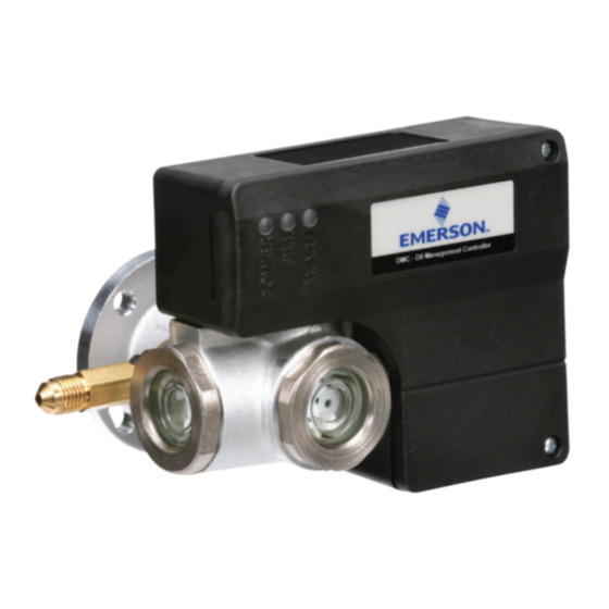
OMB/C Oil Management Control
INSTRUCTIONS FOR FIELD CHANGEOUT OF
OMB OR OMC OIL CONTROL
This instruction has been developed to minimize down time based
upon actual field experience. Read through the entire instruction before
proceeding with the change-out.
Tools Recommended: 7/16" nut driver; 7/16" open-end wrench;
adjustable wrench; slotted screwdriver; wire stripper; manifold
gauge set; refrigeration valve wrench (Additional items which may be
required depending on application: 1' of ¼" refrigerant grade copper
tubing. 2-¼" brass flare nuts; flaring tool; 3/8" male flare by ¼" female
flare adapter; 3-electrical wire nuts).
1. Disconnect all electrical power to the compressor.
2. Safely connect gauge bar hoses in the following sequence: discharge
OMC CO2
line to backseat port of an adjacent compressor service valve;
1885 psig
common line to oil pressure port on crankcase of compressor on
0/1450 psig
which control is to be changed; suction line to suction manifold on
compressor rack. (Manifold valves should be closed.)
3. Close discharge, suction, and oil feed service valves on compressor.
4. Open the gauge manifold discharge hand wheel to pressurize the
crankcase to discharge pressure. (Important: Do not exceed
allowable pressure limits set by the compressor manufacturer
for the crankcase.)
5. After pressurizing the crankcase to a safe pressure, close manifold
gage discharge wheel.
6. Open the gage manifold suction wheel to allow the high pressure in
the crankcase to meter the oil into the suction manifold.
CO2
7. After the oil is below the sight glass on the compressor crankcase,
close the suction hand wheel and safely reclaim the remaining
refrigerant pressure in the crankcase.
8. After all the pressure is depleted in the crankcase, remove the existing
oil control as follows:
(Brass)
A. Disconnect the electrical leads at the control and label each if wire
color codes change.
B. Remove flexible conduit (if used) at the junction box.
C. Disconnect the oil supply line. Note: A new one may need to be
fabricated, or an adapter required, if replacing an OMB with an OMC.
D. Remove the flange mounting bolts which hold the control to the
adapter and remove existing control.
OMC
Publicidad
Tabla de contenido

Manuales relacionados para Emerson OMB/C


Resumen de contenidos para Emerson OMB/C
- Página 1 Failure to comply can result in personal injury and/or system damage. WARNING: The OMB/C operates by using a strong magnetic sensor. It is important to keep the control free of any steel or iron particles which could accumulate on it during installation.
-
Página 2: Electrical Wiring Diagram
Closed Open in Alarm Red - Closed in Alarm Relay Brown - Open in Alarm Orange - Common Common Technical Support: 1 888 725 9797 Emerson.com/White-Rodgers PA-00388 (09/17) Emerson is a trademark of Emerson Electric Co. ©2017 All rights reserved. -
Página 3: Control Para Administrar El Aceite Omb/C
1 pie de ¼ pulg. de 4. Desconecte el suministro de tensión del sistema/OMB/C antes de la instalación/ grado refrigeración; 2 tuercas cónicas de bronce de ¼ pulg; abocardador; adaptador servicio. - Página 4 Cuando esté correctamente instalado, el tubo de colores e instale la bobina solenoide y los enchufes de corriente. Nota: No estará a un pequeño ángulo en relación al OMB/C. Ver la figura 2 a continuación. energice la bobina solenoide antes de sustituir el tubo envolvente.
-
Página 5: Controles De Gestão De Óleo Omc
à pressão atmosférica e permaneça assim. Não fazer isso pode resultar em ferimento pessoal e/ou danos ao sistema. ATENÇÃO: A OMB/C opera usando um sensor magnético forte. É importante manter o controle livre de quaisquer partículas de aço ou ferro que possam acumular nele INSTRUÇÃO PARA TROCA EM CAMPO DE CONTROLE DE ÓLEO DE... - Página 6 Aberto no alarme Vermelho - fechado no alarme Marrom - aberto no alarme Relé comum Laranja - comum Suporte técnico: 1 888 725 9797 Emerson.com/White-Rodgers PA-00388 (09/17) Emerson é uma marca registrada comercial da Emerson Electric Co. ©2017 Todos os direitos reservados.