Publicidad
Enlaces rápidos
GENERAL
This installation and maintenance instruction
sheet of the solenoid is a general supplement
to the particular I&M sheet for the valve. The
identification is made by prefix NF/WSNF to
the catalogue number (FN/FS insertion for
the global codification). Always use both
I&M sheets for installing and maintaining
the solenoid valve.
DESCRIPTION
The solenoid valves are designed in
accor-dance with annex II of the European
Directive 2014/34/EU and IECEx scheme:
IECEx 02. EC type examination certificate
LCIE 00ATEX6008X and IECEx certificate
LCI 07.0015X are in compliance with
international and European standards:
ATEX
IECEx
EN 13463-1
EN 60079-0
IEC 60079-0
EN 60079-1
IEC 60079-1
EN 60079-31
IEC 60079-31
Classification:
II 2G Ex db IIC T* Gb
II 2D Ex tb IIIC T** Db IP66/67
INSTALLATION
ASCO components are intended to be used
only within the technical characteristics as
specified on the nameplate. Changes to the
equipment are only allowed after consulting
the manufacturer or its representative. These
solenoid valves are intended for installation
in potentially explosive atmospheres, Group
IIA/IIIA, IIB/IIIB or IIC/IIIC gases, vapors,
mists or dusts (Group G/D, category 2). The
surface temperature classification depends
on wattage and ambient temperature which
are stated on the nameplate. Depending on
the ambient temperature/wattage, a heat
resistant cable, suitable for temperature as
DRAWING
DISEGNO
1
2
3
4
5
6
7
6
8
9
10
11
12
13
123620-795 Rev F ECN 275360
Page 1 of 6
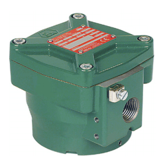
INSTALLATION AND MAINTENANCE INSTRUCTIONS
Flameproof solenoid operator NF/WSNF-M12-I (global codification Insertion FN/FS)
indicated on the nameplate, must be used.
ELECTRICAL INSTALLATION
Wiring must comply with local and national
regulations of explosion proof equipment.
For the cable/conduit entry, the enclosure
is provided with a 1/2" NPT or M20x1,5
threaded hole. Entry of external conductors
and cables must be through properly
installed and suitable certified flameproof
cable entry devices. To make connection to
the coil terminals, remove solenoid cover.
Strip the outer insulation of the cable over
approx. 150 mm and the insulation from
the leads over 8 mm. Insert wires through
the cable gland and connect wires to the
terminals of the coil. Connect cable ground
wire to the internal ground terminal. Keep
some slack in the leads between cable entry
and coil to avoid excessive strain on the
leads. Assemble the cable gland and tighten
the elastomer compression seal so that it fits
tightly around the cable. When the set screw
is unscrewed, the solenoid can be rotated
360° to select the most favorable position
for the cable entry. Close the enclosure and
tighten 4 cover screws securely to torque
indicated. The solenoid housing is provided
with an external connection facility for an
earthing or bonding conductor.
CAUTION
Electrical load must be within the range
stated on the nameplate. Failure to stay
within the electrical range of the coil
rating results in damage to or premature
failure of the coil. It will also invalidate
the approval. If the solenoid is used in a
dust environment, the risk of electrostatic
discharge shall be avoided. WARNING:
It is not permitted to have the solenoid
cover removed by unauthorized personnel.
The spigot of the solenoid cover and the
bore in the solenoid housing constitute
DESSIN
ZEICHNUNG
TEKENING
SERIES NF/WSNF-M12-I
(Global Codification Insertion FN/FS)
A
B
C
D
OPTIONAL
14
G
15
16
2 5
Ø 6 , 5
C
F
C
E
the tightly toleranced flamepath of the
flameproof solenoid. When removing
or re-assembling the solenoid cover, utmost
care should be taken to avoid any damage to
either the spigot or the bore. The flameproof
joints are not intended to be repaired. Do not
paint these surfaces. However, corrosion
inhibiting grease, such as petrolatum or
soap-thickened mineral oils, may be applied
to joint surfaces before assembly. The
grease, if applied, shall be of a type that
does not harden because of ageing, does
not contain an evaporating solvent and does
not cause corrosion of the joint surfaces.
SPECIAL CONDITION FOR SAFE USE
Solenoid valve may be used only with an
ambient temperature range as stated on
the nameplate.
SERVICE
To prevent the possibility of personal or
property damage, do not touch the solenoid.
It can become hot under normal operation
conditions. If the solenoid valve is easily
accessible, the installer must provide
protection preventing accidental contact.
MAINTENANCE
Maintenance depends on service conditions.
Periodic cleaning is recommended, the
timing of which will depend on the media
and service conditions. During servicing,
components should be examined for
excessive wear. A complete set of internal
parts is available as a spare parts kit.
If a problem occurs during installation/
maintenance or in case of doubt please contact
ASCO or authorized representative.
CAUTION: Before servicing the solenoid
valve, turn off electrical power, depressurize
valve and vent fluid to a safe area. Do not
open the solenoid when energized recently,
DRAWING
DISEGNO
CONNECTION / RACCORDEMENT / VERBINDUNG /
AANSLUITING / CONNESSIONE 1/2"NPT
PREFIX NF/WSNF (INSERTION FN/FS)
PREFIXE NF/WSNF (INSERTION FN/FS)
VORSATZ NF/WSNF (EINFÜGUNG FN/FS)
PREFISSO NF/WSNF (INSERIMENTO FN/FS)
VOORVOEGSEL NF/WSNF (TUSSENVOEGSEL FN/FS)
CONNECTION / RACCORDEMENT / VERBINDUNG /
AANSLUITING / CONNESSIONE M20x1,5
PREFIX NFET/WSNFET (INSERTION FT/FU)
PREFIXE NFET/WSNFET (INSERTION FT/FU)
VORSATZ NFET/WSNFET (EINFÜGUNG FT/FU)
PREFISSO NFET/WSNFET (INSERIMENTO FT/FU)
VOORVOEGSEL NFET/WSNFET (TUSSENVOEGSEL FT/FU)
GB
Supplied in spare part kit
FR
Livrées en pochette de rechange
DE
Enthalten im Ersatzteilsatz
IT
Disponibile nel Kit parti di ricambio
NL
Geleverd in vervangingsset
TORQUE CHART
A
7±0,5
62±5
B
1,5±0,2
12±2
C
1±0,2
8±2
D
0,5±0,1
4±1
E
20±3
175±25
F
15±2
135±15
G
4±0,5
35±5
ITEMS
NEWTON.METRES INCH.POUNDS
www.asco.com
r q GB
delay opening for 35 minutes. Solenoid must
be fully reassembled as the housing and
internal parts complete the magnetic circuit.
At screw Nr 1 replacement: use only screws
with 700 N/mm
minimum tensile strength. In
2
case of any replacement of parts by the user,
the traceability of the final product can not
be guaranteed by ASCO. Wrong assembly
will invalidate the approval.
SOLENOID/VALVE (DIS)-ASSEMBLY
Tighten the set screw, (un)screw the
complete solenoid (from)/to the valve by
means of a hookspanner.
For additional information visit us at:
www.asco.com
DESSIN
ZEICHNUNG
TEKENING
GB
DESCRIPTION
1. Screw
10. Housing
2. Cover
11. Cable entry
3. O-ring
12. Set screw
4. Clip
13. Hook wrench
5. Plate
14. Washer, spring (2x)
6. Sleeve
15. Screw (2x)
7. Coil
16. Mounting bracket
8. Yoke
9. Washer
FR
DESCRIPTION
1. Vis
10. Boîtier
2. Couvercle
11. Entrée de câble
3. Joint torique
12. Vis de l'ensemble
4. Clip
13. Clé à crochet
5. Plaque
14. Rondella élastique (2x)
6. Gaine isolante
15. Vis (2x)
7. Bobine
16. Support de montage
8. Culasse
9. Rondelle élastique
DE
BESCHREIBUNG
1. Schraube
10. Gehäuse
2. Deckel
11. Kabeleinführung
3. Dichtungsring
12. Einstellschraube
4. Klammer
13. Hakenschlüssel
5. Platte
14. Federscheibe (2x)
6. Hülse
15. Schraube (2x)
7. Magnetspule
16. Montagehalterung
8. Joch
9. Scheibe
IT
DESCRIZIONE
1. Vite
10. Sede
2. Coperchio
11. Ingresso del cavo
3. Anello di ritenuta
12. Vite di fermo
4. Clip
13. Chiave per dadi
5. Targhetta
14. Rondella elastica (2x)
6. Manicotto
15. Vite (2x)
7. Bobina
16. Squadra di fissaggio
8. Giogo
9. Rondella
NL
BESCHRIJVING
1. Bout
10. Huis
2. Deksel
11. Kabeldoorvoer
3. O-ring
12. Stelschroef
4. Bevestigingsclip
13. Haaksleutel
5. Plaat
14. Veerring (2x)
6. Huls
15. Schroef (2x)
7. Spoel
16. Montagebeugel
8. Juk
9. Ring
Date: 2017-06-20
Publicidad

Manuales relacionados para Asco NF/WSNF-M12-I Serie


Resumen de contenidos para Asco NF/WSNF-M12-I Serie
- Página 1 INSTALLATION earthing or bonding conductor. MAINTENANCE ASCO components are intended to be used Maintenance depends on service conditions. only within the technical characteristics as CAUTION Periodic cleaning is recommended, the specified on the nameplate.
- Página 2 Teile komplettiert wird. Bei Austausch von Schraube faire via des équipements d’entrée de câble antidéflagrants, dûment ne peut pas être garantie par ASCO. Un montage incorrect entraîne zugelassene flammfeste Kabeleinführungsvorrichtungen eingeführt Nr. 1: nur Schrauben mit mindestens 700 N/mm Zugfestigkeit agréés et correctement installés.
- Página 3 Los cambios en el equipo sólo estarán permitidos después de con- i utrustningen tillåts endast efter konsultation med tillverkaren eller o en caso de dudas, por favor póngase en contacto con ASCO nyligen blivit strömförande utan vänta i 35 minuter. Vid byte av skruv sultar al fabricante o a su representante.
- Página 4 Durante a manutenção, INSTALLERING Os componentes da ASCO devem ser utilizados apenas de acordo ikke nøle med å ta kontakt med ASCO/JOUMATIC eller dennes os componentes deverão ser observados quanto ao possível des- ASCO-komponenter er kun beregnet på...
- Página 5 že uživatel provede výměnu jakýchkoli dílů, nemůže ASCO Opisywane zawory elektromagnetyczne są przeznaczone do lub w razie pytań należy skontaktować się z firmą ASCO lub jej které jsou uvedeny na typovém štítku. V závislosti na okolní teplotě/ montażu w środowiskach zagrożonych wybuchem, w miejscach zaručit dohledatelnost konečného výrobku.
- Página 6 és csatlakoztassa õket a tekercs Αφαιρέστε την εξωτερική μόνωση του καλωδίου, σε μήκος περίπου χρήστη, η ASCO δεν μπορεί να εγγυηθεί την ανιχνευσιμότητα του kapcsaihoz. A kábel földelővezetékét csatlakoztassa a belsõ 150 mm, και τη μόνωση των αγωγών, σε μήκος 8 mm. Περάστε...