Tabla de contenido
Publicidad
Enlaces rápidos
*-/
!
Installation Guide
1
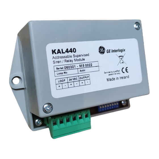
Electrical connections:
3
supply connectors;
Relay output connectors;
5
Status LED.
D
ESCRIPTION
The KAL440 allows a monitored relay output for sounders or
solenoid valves in the detection system and monitors the line they
are connected to. The module is used in detection systems that
require an auxiliary 24 VDC power supply. The status LED is lit
constantly during alarm.
I
NSTALLATION
For general guidelines on fire system planning,
design, installation, commissioning, use and
maintenance refer to the EN54-14 (2001) standard
and local regulations.
The module is designed for cabinet installation and must be
protected against environmental agents. The 24 VDC power
supply is taken from an auxiliary power source. The power supply
should be disconnected during installation.
Module configuration
Use DIP switch 8 to configure the module.
•
If set to ON the KAL440 operates as a monitored relay
module.
•
If set to OFF it operates as a sounder module.
The relay output provides only the voltage received from the
auxiliary power supply (24 VDC) – ensure that this is sufficient for
your installation.
© (2004) GE Interlogix B.V.. All rights reserved.
Version 3-1 / August 2004
1050794
2
Loop connectors;
Auxiliary power
4
DIP Switches;
KAL440 Addressable Supervised Relay Module
The module will only allow sounders to be silenced from the
control panel if configured to operate as a sounder module (the
default setting).
Addressing
Each module requires a numeric address between 128 and 253 for
identification purposes. This is set using DIP switches 1-7 (see
Table 1: DIP switch address settings). DIP switch 8 is reserved for
module configuration.
M
AINTENANCE AND
Basic maintenance is reduced to a yearly inspection. Do not
modify internal wiring or circuitry.
To test:
1.
Configure the module as an output to be activated by a
detector or manual call point.
2.
Remove a detector head from its base or activate a manual
call point.
If the status LED and control panel fail to indicate the test all
connections should be checked and the module address verified.
T
ECHNICAL SPECIFICATIONS
Operating voltage ...........................................................22 – 38 VDC
Current consumption at 24 VDC (quiescent)...........................110 µA
Current consumption at 35 VDC (quiescent)...........................135 µA
Current consumption (alarm)................................................< 3.6 mA
Current consumption - 24 VDC aux supply (quiescent) ...........23 mA
Current consumption - 24 VDC aux supply (alarm)* ................23 mA
End-of-line resistor .................................................................... 4K7Ω
Operating temperature ................................................. -10ºC to 50ºC
Storage temperature .................................................... -10ºC to 70ºC
Relative humidity ................................................................. 95% max
Dimensions............................................................ 117 x 80 x 44 mm
Installation Guide
T
ESTING
Publicidad
Tabla de contenido

Manuales relacionados para GE KAL440


Resumen de contenidos para GE KAL440
- Página 1 Use DIP switch 8 to configure the module. Current consumption (alarm)..........< 3.6 mA Current consumption - 24 VDC aux supply (quiescent) ...23 mA • If set to ON the KAL440 operates as a monitored relay module. Current consumption - 24 VDC aux supply (alarm)* ....23 mA •...
-
Página 2: Descripción
Morsetti ESCRIPCIÓN alimentazione ausiliaria; Morsetti uscita sirena/relé; El KAL440 posibilita la incorporación de un relé vigilado para Commutatori DIP-switch; LED di stato. aquellos equipos de los que, por su importancia, es necesario vigilar la línea a la que están conectados. El módulo está indicado ESCRIZIONE para sistemas que necesitan una fuente de alimentación de 24... -
Página 3: Especificações Técnicas
DIP Switches; LED de estado. ESCRIÇÃO O KAL440 permite uma output de relé monitorizada para sirenes ou válvulas de solenóide no sistema de detecção e monitoriza a linha à qual estão ligadas. O módulo é utilizado nos sistemas de detecção que requerem uma alimentação auxiliar de 24 VDC. - Página 4 Table 1 / Tabla 1 Tabella 1 / Tabela 1 1 2 3 4 5 6 7 8 1 2 3 4 5 6 7 8 1 2 3 4 5 6 7 8 1 2 3 4 5 6 7 8...