Tabla de contenido
Publicidad
Enlaces rápidos
!
Installation Guide
1
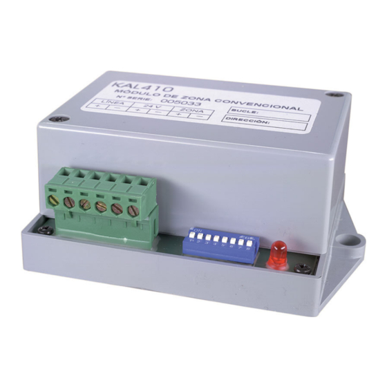
Electrical connections:
3
supply connectors;
Zone output connectors (C, NC, NO);
5
DIP Switches;
Status LED.
D
ESCRIPTION
The KAL410 may be used in detection systems with no area
subdivision and/or when exact location data is not required.
One module may be used to connect up to 20 conventional
detectors and an unlimited number of manual call points or NO
contacts to the fire detection system.
I
NSTALLATION
For general guidelines on fire system planning,
design, installation, commissioning, use and
maintenance refer to the EN54-14 (2001) standard
and local regulations.
The module is designed for cabinet installation and must be
protected against environmental agents. The power supply should
be disconnected during installation.
An end-of-line resistor (4K7Ω) must be installed at the end of the
detection zone wires.
The 24 V power supply can be taken from the loop or from an
auxiliary power source. If more than 10 KAL400 series modules
are connected to a loop, an auxiliary power supply is
recommended. Always verify large installations using the loop load
calculator to confirm that enough power is available on the loop.
Power supply configuration
To set the module power supply remove the unit cover and
configure jumpers JMP1 and JMP2. See Figure 2: power supply
jumper configuration.
© (2004) GE Interlogix B.V.. All rights reserved.
Version 3-1 / August 2004
1050792
2
Loop connectors;
Auxiliary power
KAL410 Addressable Conventional Zone Module
Figure 2: power supply jumper configuration
4
Loop powered.
Do not connect a 24 VDC auxiliary power supply to
the module if power is supplied by the loop.
Status LED
The status LED is configured using DIP switch 8 in the DIP switch
selector: If set to ON the LED will flash during all communications
between the module and the control panel. If set to OFF it will flash
only during selected communications between the module and
control panel (see control panel manual for further details). The
status LED is lit constantly during alarm.
Addressing
Each module requires a numeric address between 128 and 253 for
identification purposes. This is set using DIP switches 1-7 (see
Table 1: DIP switch address settings). DIP switch 8 is reserved for
configuration of the status LED.
M
AINTENANCE AND
Basic maintenance is reduced to a yearly inspection. Do not
modify internal wiring or circuitry.
To test remove a detector head from its base or activate a manual
call point connected to the module detection zone.
If the status LED and control panel fail to indicate the test all
connections should be checked and the module address verified.
T
ECHNICAL SPECIFICATIONS
Operating voltage ...........................................................22 – 38 VDC
Installation Guide
24 VDC auxiliary power supply.
T
ESTING
Publicidad
Tabla de contenido

Manuales relacionados para GE KAL410


Resumen de contenidos para GE KAL410
- Página 1 Loop powered. 24 VDC auxiliary power supply. ESCRIPTION The KAL410 may be used in detection systems with no area Do not connect a 24 VDC auxiliary power supply to subdivision and/or when exact location data is not required. the module if power is supplied by the loop.
-
Página 2: Descripción
Corriente de consumo 24 VDC (reposo) ........90 µA ESCRIPCIÓN Corriente de consumo 35 VDC (reposo) .........105 µA El KAL410 está indicado cuando el área a proteger no tiene Corriente de consumo (alarma)..........< 3.0 mA subdivisiones en su interior o no requiere que haya un Corriente de consumo - 24 VDC alim. -
Página 3: Specifiche Tecniche
(repouso)*................200 µA ESCRIÇÃO Consumo de corrente - Alimentação aux. de 24 VDC O KAL410 pode ser utilizado em sistemas de detecção sem (alarme) .................< 85 mA subdivisão de área e/ou quando não são necessários dados Consumo de corrente – Alimentação por loop (repouso)..6,5 mA exactos de localização. - Página 4 Resistência de fim de linha ............4K7Ω Temperatura de funcionamento ........-10ºC a 50ºC Temperatura de armazenamento........-10ºC a 70ºC Humidade relativa .............. 95% máx. Dimensões .............117 x 80 x 44 mm * Excluindo os dispositivos do loop.
- Página 5 Table 1 / Tabla 1 / Tabella 1 / Tabela 1 / 1 2 3 4 5 6 7 8 1 2 3 4 5 6 7 8 1 2 3 4 5 6 7 8 1 2 3 4 5 6 7 8...