Tabla de contenido
Publicidad
Enlaces rápidos
!
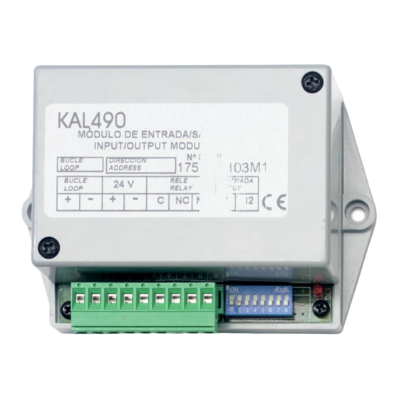
Installation Guide
1
Electrical connections:
3
supply connectors;
Relay connectors (C, NC, NO);
5
connectors;
DIP Switches;
D
ESCRIPTION
The KAL490 provides a remote input and a potential free voltage
relay output to an analogue fire system loop. The input signal is
constantly monitored and and its status displayed at the control
panel. The output is fail-to-safe. Auxiliary supply monitoring is also
included.
The output has three positions: Common (C), Normally Open (NO)
and Normally Closed (NC). In quiescent mode C and NC electrical
contacts are connected. When output is activated C is connected
to NO.
The input does not have polarity. When electrical contacts are not
connected the module remains in quiescent mode.
The status LED is lit constantly during alarm.
I
NSTALLATION
For general guidelines on fire system planning,
design, installation, commissioning, use and
maintenance refer to the EN54-14 (2001) standard
and local regulations.
The module is designed for cabinet installation and must be
protected against environmental agents. The power supply should
be disconnected during installation.
The 24 V power supply can be taken from the loop or from an
auxiliary power source.
If more than 10 KAL400 series modules are connected to a loop,
an auxiliary power supply is recommended. Always verify large
© 2005 GE Interlogix B.V.. All rights reserved.
Version 2-2 / July 2005
1052525
2
Loop connectors;
Auxiliary power
4
6
Status LED.
KAL490 Addressable Retention Module
installations using the loop load calculator to confirm that enough
power is available on the loop.
Power supply configuration
To set the module power supply remove the unit cover and
configure jumpers JMP1 and JMP2. See Figure 2: power supply
Input
jumper configuration.
Figure 2: power supply jumper configuration
Loop powered.
Do not connect a 24 VDC auxiliary power supply to
the module if power is supplied by the loop.
Addressing
Each module requires a numeric address between 128 and 253 for
identification purposes. This is set using DIP switches 1-7 (see
Table 1: DIP switch address settings). DIP switch 8 is not used.
M
AINTENANCE AND
Basic maintenance is reduced to a yearly inspection. Do not
modify internal wiring or circuitry.
To test the module:
•
Activate the input signal and check the activation message at
the control panel.
•
Activate the relay from the control panel and check the module
relay changes position.
If the status LED and control panel fail to indicate the test all
connections should be checked and the module address verified.
Installation Guide
24 VDC auxiliary power supply.
T
ESTING
Publicidad
Tabla de contenido

Manuales relacionados para GE Interlogix KAL490


Resumen de contenidos para GE Interlogix KAL490
- Página 1 If the status LED and control panel fail to indicate the test all an auxiliary power supply is recommended. Always verify large connections should be checked and the module address verified. © 2005 GE Interlogix B.V.. All rights reserved. Version 2-2 / July 2005 1052525...
-
Página 2: Descripción
Asignación de la dirección ECHNICAL SPECIFICATIONS Cada módulo tiene que estar identificado con una dirección Operating voltage ............22 – 38 VDC numérica entre 128 y 253. Esta dirección puede ser asignada Current consumption at 24 VDC (quiescent) ......110 µA utilizando los microinterruptores 1-7. Ver Tabla 1: Configuración Current consumption at 35 VDC (quiescent) ......135 µA del microinterruptor. -
Página 3: Specifiche Tecniche
Configurazione alimentazione O LED de estado está constantemente aceso durante o alarme. Per impostare la modalità di alimentazione del modulo, rimuovere NSTALAÇÃO il coperchio dell’unità e configurare i ponticelli JMP1 e JMP2. Vedere la figura 2: configurazione ponticelli alimentazione. Para directrizes gerais sobre planeamento, design, instalação, comissionamento, utilização e Figura 2: configurazione ponticelli alimentazione manutenção de sistemas de incêndio, consulte a... -
Página 4: Installatie
Stromaufnahme - 24 VDC über zus. Netzteil Der Ausgang bietet drei Anschlussklemmen: Gemeinsam (C), (Alarmzustand) ..............< 50 mA Normal geöffnet (NO) und Normal geschlossen (NC). Im Stromaufnahme - Ringversorgung (Ruhezustand)....350 µA Ruhezustand sind die C- und NC-Kontakte verbunden. Bei Stromaufnahme - Ringversorgung (Alarmzustand)....< 3,4 mA Aktivierung des Ausgangs wird C mit NO verbunden. -
Página 5: Руководство По Установке
Если к шлейфу подключено более 10 модулей серии KAL400, рекомендуется использовать вспомогательный блок питания. Sluit geen externe voeding van 24 V gelijkstroom aan Большие системы всегда необходимо проверять с помощью als de module via de lus gevoed wordt. калькулятора нагрузки на шлейф для подтверждения того, что уровень... - Página 7 Table 1 / Tabla 1 / Tabella 1 / Tabela 1 / 1 2 3 4 5 6 7 8 1 2 3 4 5 6 7 8 1 2 3 4 5 6 7 8 1 2 3 4 5 6 7 8...