Tabla de contenido
Publicidad
Idiomas disponibles
Idiomas disponibles
Enlaces rápidos
Publicidad
Tabla de contenido

Manuales relacionados para LGB 10560


Resumen de contenidos para LGB 10560
- Página 1 Entkupplungsgleis 10560...
-
Página 2: Tabla De Contenido
Asymmetrical Couplers Symmetrical Couplers Knuckle Couplers Coupling Uncoupling Remote Control Electric Uncoupler No. 10560 Assembling the Electric Uncoupler Electrical Connection of the Electric Uncoupler Electric Uncoupler with EPL Supplementary Switch No. 12030 10 Constant Uncoupler No. 10520 The Constant Uncoupler and Symmetrical Couplers... - Página 3 Agganciamento Ontkoppelen Sganciamento Op afstand bedienbare elektrische ontkoppelrail 10560 Binario di sganciamento elettromagnetico azionato a distanza 10560 25 Montage van de ontkoppelrail 10560 Montaggio del binario di sganciamento elettromagnetico 10560 26 Elektrische aansluiting van de ontkoppelrail Collegamento elettrico del binario di sganciamento...
-
Página 4: Vorbemerkungen
Zugverband problemlos herausgenommen werden. lungsgleis 10560 einwandfrei entkuppeln. Symmetrische Kupplung Kuppeln Die LGB-Fahrzeuge ab Baujahr 1980 kann man leicht mit Das Kuppeln geschieht durch einfaches Aneinander- einem zweiten Kupplungshaken ausrüsten. So entsteht schieben der Fahrzeuge, wobei der Kupplungshaken eine symmetrische Kupplung. Ihre Pluspunkte: bzw. -
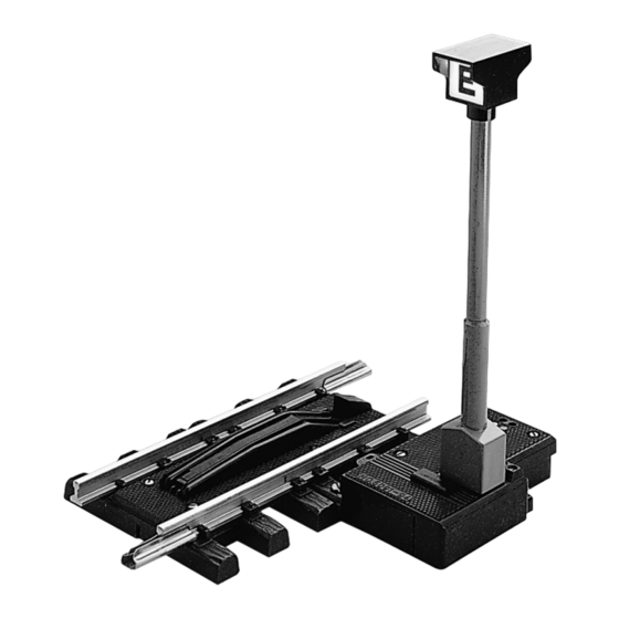
Página 5: Fernbedientes Elektro-Entkupplungsgleis 10560
Fernbedientes Elektro-Entkupplungsgleis 10560 Das Bild 1 zeigt die Funktionselemente des Elektro- Entkupplungsgleises 10560: Die zu entkuppelnden Fahrzeuge werden mit ihren Kupplungen über der Entkupplungsbohle zum Halten ge- 1. Stellhebel des Elektroantriebes bracht. Durch Tastendruck am Stellpult 51750 hebt sich 2. Kabelklemmen für Fernbedienungsanschluss an... -
Página 6: Montage Des Elektro-Entkupplungsgleises 10560
Montage des Elektro-Entkupplungsgleises 10560 Dauerentkuppler 10520 Bild 2 zeigt die notwendigen Handgriffe: Der Dauerentkuppler 10520 kann an jeder beliebigen Stelle der Gleisanlage auf die Schwellen gerader oder 1. Stellschieber nach links drücken, wobei sich die gebogener Gleise aufgesteckt werden. Beim langsamen Kupplungsbohle hebt. -
Página 7: Der Dauerentkuppler Und Die Symmetrische Kupplung
(und zusätzlich für Dauerentkuppler 10520, sofern sym- gilt auch bei Verwendung eines Elektro-Entkupplungs- metrische Kupplungen verwendet werden). gleises, bei dem zusätzlich ein Dauerentkuppler 10560 Entkuppler müssen so in Weichenstraßen eingebaut eingebaut werden muss, um das Absenken beider Kupp- werden, dass die Fahrzeugbegrenzung abgekuppelter... -
Página 8: Introductory Notes
In this way, you can Coupling create a symmetrical coupling system. Symmetrical cou- No matter which LGB coupling system is use, LGB rolling pling makes it easier to execute complicated switching stock can be easily coupled by lightly touching the cars and coupling operations. -
Página 9: Uncoupling
No. 50750), the uncoupling plank is raised, the hook part The electric uncoupler is 150 mm long and corresponds of the coupler is lowered (or, if you have LGB’s knuckle to one half of a regular LGB No. 10150 straight track coupler, one side is released) and your LGB cars are piece. -
Página 10: Assembling The Electric Uncoupler
Assembling the Electric Uncoupler Constant Uncoupler No. 10520 Fig. 2 shows the necessary procedure: The constant uncoupler No. 10520 can be installed in the ties of any straight or curved track. When the train is run 1. Push the slider to the left to raise the uncoupling slowly over the constant uncoupler, the coupler hook is plank. -
Página 11: Installation Recommendations
Installation Recommendations Uncoupling tracks works best when used in train station tracks and shunting tracks. Fig. 5 shows some examples of installation of the electric uncoupler (including the arrangement where the electric uncoupler works with constant uncoupler to unclouple trains with symmetrical couplers). -
Página 12: Introduction
LGB à quatre essieux, construits Attelage asymétrique à partir de 1980. Cependant, il est très simple d’en Les véhicules LGB construits à partir de 1980 ont, sur le équiper ultérieurement les wagons. Des problèmes de côté, un crochet d’attelage pivotant dans tous les sens. -
Página 13: Rail De Dételage Électrique Télécommandé 10560
Rail de dételage électrique télécommandé 10560 La Img. 1 montre les éléments permettant le fonctionne- ment du rail de dételage 10560: Véhicules et attelages sont amenés à s’arrêter par le madrier de dételage. En appuyant sur la touche du 1. levier de commande électrique pupitre de commande 51750, le madrier se soulève, le... -
Página 14: Montage Du Rail De Dételage Électrique 10560
Montage du rail de dételage électrique 10560 Dételeur permanent 10520 Le Img. 2 montre la façon de procéder: Le dételeur permanent 10520 peut être installé à n’importe quel endroit du réseau que ce soit sur un rail 1. Appuyer le curseur de réglage vers la gauche. Le courbe. -
Página 15: Dételeur Permanent Et Attelage Symétrique
électrique 10560 (et, en site en plus un dételeur permanent 10560 pour assurer le cas d’utilisation d’un système d’attelage symétrique, du bon abaissement des 2 crochets d’attelage symétrique. -
Página 16: Opmerking Vooraf
1. Haakkoppeling (asymmetrisch of symmetrisch) de in Amerika gebruikelijke automatische koppeling. Dit 2. Klauwkoppeling zijn de bijzonderheden: Af fabriek zijn de LGB voertuigen met de asymmetrische 1. beweegbare koppelingskop waardoor perfect koppel- haakkoppeling uitgevoerd. Bij elke wagen is een tweede end ook in bogen. -
Página 17: Op Afstand Bedienbare Elektrische Ontkoppelrail 10560
10560 Afb. 1 toont de functionerende delen van de elektrische of met het vaste ontkoppelstuk 10520 gebeuren. ontkoppelingrail 10560. 1. stelhendel van de elektrische aandrijving. Op afstand bedienbare elektrische ontkoppelrail 10560 2. draadklemmen voor de aansluiting bedieningspaneel. -
Página 18: Montage Van De Ontkoppelrail 10560
Montage van de ontkoppelrail 10560 Vast ontkoppelstuk 10520 Afb. 2 toont de noodzakelijke handelingen: Het vaste ontkoppelstuk 10520 kan op elke gewenste plaats op de baan, op de biels van een recht of gebogen 1. stelhendel naar links drukken waardoor de ontkoppel- railstuk worden gestoken. -
Página 19: Het Vaste Ontkoppelstuk En De Symmetrische Koppeling
De afb. 5 toont enige inbouw twee vaste ontkoppelstukken achter elkaar inbouwen voorbeelden voor de elektrische ontkoppelrail 10560 ( en aangezien er twee koppelingshaken gelijktijdig gelost het extra ontkoppelstuk 10520, voor zover symmetrische moeten worden. -
Página 20: Observaciones Preliminares
2. los trenes se pueden deslizar sin problemas con el Enganche asimétrico enganche de garras. Los vehículos LGB a partir del año de fabricación 1980 El enganche de garras es un enganche simétrico. Ha incorporan en un lado un gancho de enganche que está... -
Página 21: Desacoplamiento
2. Bornes para cables para conectar el control remoto delo real se puede realizar con una vía de desenganche al panel de mando eléctrico con control remoto 10560 o con el densengan- 3. Bornes para cables para conectar la luz del poste chador permanente 10520. -
Página 22: Montaje De La Vía De Desenganche Eléctrico 10560
Montaje de la vía de desenganche eléctrico 10560 Desenganchador permanente 10520 La figura 2 muestra las operaciones manuales necesa- El desenganchador permanente 10520 se puede enchuf- rias: ar en un punto cualquiera de la instalación de vías en las traviesas de vías rectas o curvas. Al pasar lentamente 1. -
Página 23: El Desenganchador Permanente Y El Enganche Simétrico
10560 con el fin de garantizar un enganche desacoplados no penetre en el gálibo de vías contiguas. simétrico y, por tanto, un desenganche perfecto. -
Página 24: Osservazioni Preliminari
Aggancio simmetrico e nell’esercizio di manovra. I rotabili LGB a partire dall’anno di costruzione 1980 si L’aggancio a ganascia si può sganciare senza inconve- possono facilmente equipaggiare con un secondo den- nienti con il binario di sganciamento elettromagnetico tello di aggancio. -
Página 25: Sganciamento
2. Morsetti dei cavetti per collegamento da azionamento avvenire con un binario di sganciamento elettromagneti- a distanza al quadro di comando co comandato a distanza 10560 oppure con lo sgancia- 3. Morsetti dei cavetti per collegamento da illuminazio- tore permanente 10520. -
Página 26: Montaggio Del Binario Di Sganciamento Elettromagnetico 10560
Montaggio del binario di sganciamento elettromagne- Sganciatore permanente 10520 tico 10560 Tale sganciatore permanente 10520 può venire innestato La figura 2 mostra le manipolazioni necessarie: in qualsiasi punto a piacere dell’impianto dei binari sopra le traversine di binari diritti oppure curvi. In caso 1. -
Página 27: Lo Sganciatore Permanente E L'aGgancio Simmetrico
10560 (ed in aggiunta per sganciatori stesso tempo due dentelli di aggancio. Questo vale permanenti 10520, ammesso che vengano utilizzati degli anche in caso di impiego di un binario di sganciamento agganci simmetrici). - Página 28 Bild 1 Bild 2 Fig. 1 Fig. 2 Img. 1 Img. 2 Afb. 1 Afb. 2 Fig, 1 Fig, 2 Fig, 1 Fig, 2...
- Página 29 Bild 3 Elektrischer Anschluss des Entkupplungsgleises Fig. 3 Electrical Connection of the Electric Uncoupler Img. 3 Connexion électrique de la voie de dételage Afb. 3 Elektrische aansluiting van de ontkoppelrail Fig. 3 Conexión eléctrica de la vía de desenganche Fig. 3 Collegamento elettrico del binario di sgancia- mento...
- Página 30 10560 Bild 4 Elektro-Entkupplungsgleis mit Zusatzschalter 12030 51750 Fig. 4 Electric Uncoupler with EPL Supplementary Switch No. 12030 Img. 4 Rail de dételage électrique avec interrupteur supplémentaire 12030 Afb. 4 Elektrische ontkoppelrail met schakelaar 12030 Fig. 4 Vía de desenganche eléctrico con interruptor auxiliar 12030...
- Página 31 Bild 5 Einbauvorschläge Fig. 5 Installation Recommendations Img. 5 Recommandations de montage Afb. 5 Inbouw voorbeelden Fig. 5 Propuestas de montaje Fig. 5 Suggerimenti di installazione...
- Página 32 Gebr. Märklin & Cie. GmbH Stuttgarter Straße 55 - 57 73033 Göppingen 129664/0714/Sm3Ef Germany Änderungen vorbehalten www.maerklin.com/en/imprint.html www.lgb.de © Gebr. Märklin & Cie. GmbH...