Tabla de contenido
Publicidad
Idiomas disponibles
Idiomas disponibles
Enlaces rápidos
Publicidad
Tabla de contenido

Manuales relacionados para Festo CPX-2AE Serie


Resumen de contenidos para Festo CPX-2AE Serie
- Página 1 CPX-Terminal Kurz- beschreibung Brief description CPX-Analog- EA-Module CPX-2AE… CPX-4AE… CPX-2AA… CPX analogue I/O modules CPX-2AE… CPX-4AE… CPX-2AA… – Deutsch – English – Español – Français – Italiano – 中文 758645 1107d...
- Página 2 ..........Edition: 1107d Original: de © (Festo AG & Co., D-73726 Esslingen, Germany, 2011) Internet: http://www.festo.com E-Mail: service_international@festo.com...
- Página 3 Anschluss des CPX-Terminals an. S Die EA-Module enthalten elektrostatisch gefährdete Bauelemente. Berühren Sie deshalb keine Bauele- mente. Beachten Sie die Handhabungsvorschriften für elektrostatisch gefährdete Bauelemente. Hinweis Nehmen Sie nur ein komplett montiertes und verdrahte- tes CPX-Terminal in Betrieb. Festo CPX-AX 1107d Deutsch...
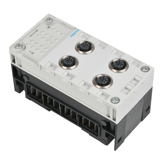
- Página 4 Anschlüssen EA-Modul * Elektronikmodul ggf. mit DIL-Schaltern (siehe Abschnitt 3.3) Verkettungsblock * mit Stromschienen Elektrische Steck- verbindung LEDs des EA-Moduls Schrauben, Anzugs- drehmoment 0,9 … 1,1 Nm exemplarische Darstellung Bedeutung – Modul-Fehler-LED (Sammelstörungsanzeige) (rot) – Kanalfehler-LED Festo CPX-AX 1107d Deutsch...
- Página 5 – – – -AB-8-M8-3POL – – -AB-8-M8-4POL – – – – -AB-8-KL-4POL • • • • -AB-1-SUB-BU-25POL • • • • – -AB-4-HARX2-4POL – – – -AB-4-M12-8POL – – – – • Kombinierbar – Nicht kombinierbar Festo CPX-AX 1107d Deutsch...
- Página 6 Verwenden Sie bei einer Kombination von Anschluss- blöcken und Verkettungsblöcken Metall auf Kunststoff bzw. Kunststoff auf Metall grundsätzlich die für den Verkettungsblock geeigneten Schrauben: – bei Kunststoff-Verkettungsblöcken gewindefur- chende Schneidschrauben – bei Metall-Verkettungsblöcken Schrauben mit metri- schem Gewinde Festo CPX-AX 1107d Deutsch...
- Página 7 Entsprechend für Kanal 1 Entsprechend für Kanäle Schalter 1 2 + 3 Das Modul 4AE-U-I hat keine DIL-Schalter. Nehmen Sie dort alle Einstellungen mit der Parametrierung vor. Informationen dazu finden Sie in der Beschreibung der CPX-Analog-EA-Module (P.BE-CPX-AX-…). Festo CPX-AX 1107d Deutsch...
- Página 8 – externer FE-Anschluss ohne Verbindung zum FE-Pin des EA-Steckers. Empfehlung: Schließen Sie den Kabelschirm beidseitig an FE mit ausreichendem Potenzialausgleich an. Wenn der Kabelschirm einseitig an FE angeschlossen wird, sollte dieser auf der “Signalempfänger-Seite” angeschlossen werden. Festo CPX-AX 1107d Deutsch...
-
Página 9: Technische Daten
0 ... 10 V 0 ... 20 mA / 4 ... 20 mA – Auflösung (A/D-Wandlung) 12 Bit (intern), skalierbar auf 15 Bit + Vorzeichen – Modulzykluszeit 2AE-U-I: ≤ 4 ms / 4AE-I: ≤ 10 ms Festo CPX-AX 1107d Deutsch... - Página 10 (s. Beschreibung P.BE-CPX-AX...) – Verpolschutz 24V-Last- Eingang – Rückspannungsfestigkeit Max. 30 V – Galvanische Trennung – zwischen Kanal und Ja (Aufhebung der Potential- 24 V trennung bei Verwendung der internen Sensorversorgung) – zwischen den Kanälen Nein Festo CPX-AX 1107d Deutsch...
- Página 11 60 mA – Eingangswiderstand ≥ 100 kΩ ≤ 100 Ω (typ. 70 Ω) – Zulässige Potenzialdifferenz – zwischen Eingängskanälen AC 1 V AC 0 V – zwischen Eingängen u. FE DC 30 V DC 30 V Festo CPX-AX 1107d Deutsch...
- Página 12 (s. Beschreibung P.BE-CPX-AX...) – Verpolschutz 24V-Last- Eingang – Rückspannungsfestigkeit Max. 30 V – Galvanische Trennung – zwischen Kanal und Ja (Aufhebung der Potential- 24 V trennung bei Verwendung der internen Sensorversorgung) – zwischen den Kanälen Nein Festo CPX-AX 1107d Deutsch...
- Página 13 Max. 1 mH – Kurzschluss-Schutz – – Kurzschluss-Strom ca. 20 mA – – Leerlaufspannung – 18 V – Zulässige Potenzial- differenzen – zwischen Ausgangs- AC 0 V kanälen – zwischen AGND und FE DC 30 V Festo CPX-AX 1107d Deutsch...
- Página 14 (s. Beschreibung P.BE-CPX-AX...) – Verpolschutz 24 V-Aktor- versorgung – Rückspannungsfestigkeit Max. 30 V – Galvanische Trennung – zwischen Kanal und 24 V Ja (Aufhebung der Potential- trennung bei Verwendung der internen Aktorversorgung) – zwischen den Kanälen Nein Festo CPX-AX 1107d Deutsch...
- Página 15 Mit Steckverbinder im gesteckten Zustand oder mit Schutzkappe ISK-M12; bei Verwendung von Schnellverbindern, Anweisung des Herstellers beachten Mit Steckverbinder im gesteckten Zustand oder mit Schutzkappe ISK-M12 Mit Abdeckung AK-8KL und Verschraubungsbausatz VG-K-M9: IP 65/IP 67 Mit Stecker SD-SUB-D-ST25: IP 65 Festo CPX-AX 1107d Deutsch...
- Página 16 Festo CPX-AX 1107d Deutsch...
- Página 17 S The I/O modules contain electrostatically sensitive devices. For this reason, do not touch any compo- nents. Observe the handling specifications for electrostatically sensitive devices. Note Only put a completely assembled and wired CPX terminal into commission. Festo CPX-AX 1107d English...
- Página 18 (see section 3.3) Interlinking block * with contact rails Electrical plug connector I/O module LEDs Screws, tightening torque 0.9 ... 1.1 Nm exemplary representation Meaning – Module fault LED (group fault display) (Red) – Channel fault LED Festo CPX-AX 1107d English...
-
Página 19: Installation Instructions
– – – -AB-8-M8-4POL – – – – -AB-8-KL-4POL • • • • -AB-1-SUB-BU-25POL • • • • -AB-4-HARX2-4POL – – – – -AB-4-M12-8POL – – – – • Can be combined – Cannot be combined Festo CPX-AX 1107d English... - Página 20 – for plastic interlinking blocks use thread-cutting screws – for metal interlinking blocks use screws with metric thread Festo CPX-AX 1107d English...
- Página 21 1 2 + 3 Module 4AE-U-I does not have a DIL switch. Conduct all settings here by using parameterisation. Further informa- tion can be found in the manual for the CPX analogue I/O modules (P.BE-CPX-AX-…). Festo CPX-AX 1107d English...
- Página 22 Recommendation: Connect the cable shield to both sides of the FE with sufficient equipotential bonding. If the cable screen is connected to one side of the FE, it should be con- nected to the “signal receiver” side. Festo CPX-AX 1107d English...
-
Página 23: Technical Data
0 to 10 V 0 to 20 mA/ 4 to 20 mA – Resolution (analogue-digital 12 Bit (internal), converter) scaleable to 15 Bit + prefix – Module cycle time 2AE-U-I: ≤ 4 ms/4AE-I: ≤ 10 ms Festo CPX-AX 1107d English... - Página 24 – Inverse polarity protection 24 V load input – Inverse voltage resistance Max. 30 V – Electrical isolation – Between channel and Yes (release electrical isolation by 24 V using the internal sensor supply) – Between the channels Festo CPX-AX 1107d English...
- Página 25 – Input resistance ≥ 100 kΩ ≤ 100 Ω (type 70 Ω) – Permissible potential difference – Between input channels AC 1 V AC 0 V – Between inputs and FE DC 30 V DC 30 V Festo CPX-AX 1107d English...
- Página 26 – Inverse polarity protection 24 V load input – Inverse voltage resistance Max. 30 V – Electrical isolation – Between channel and Yes (release electrical isolation by 24 V using the internal sensor supply) – Between the channels Festo CPX-AX 1107d English...
- Página 27 – Short circuit protection – – Short circuit current Approx. 20 mA – – Open circuit voltage – 18 V – Permissible potential differences – Between output channels AC 0 V – Between AGND and FE DC 30 V Festo CPX-AX 1107d English...
- Página 28 – Reverse polarity protection 24 V actuator supply – Inverse voltage resistance Max. 30 V – Electrical isolation – Between channel and Yes (release electrical isolation by 24 V using the internal actuator supply) – Between the channels Festo CPX-AX 1107d English...
- Página 29 With connected plug connector or ISK-M12 protective cap; if using quick connectors, observe manufacturer instructions With connected plug connector or ISK-M12 protective cap With AK-8KL cover and VG-K-M9 fittings kit: IP 65/IP 67 With SD-SUB-D-ST25 plug: IP 65 Festo CPX-AX 1107d English...
- Página 30 Festo CPX-AX 1107d English...
- Página 31 Tenga en cuenta las especificaciones sobre manipu- lación de elementos sensibles a las descargas elec- trostáticas. Importante Ponga en servicio un terminal CPX sólo cuando se halle completamente montado y cableado. Festo CPX-AX 1107d Español...
-
Página 32: Elementos De Conexión E Indicación
Conector eléctrico enchufable LED del módulo I/O Tornillos, par de apriete 0,9 ... 1,1 Nm Ejemplo Significado (rojo) – LED de errores del módulo (indicador colectivo de averías) – LED de fallo del canal Festo CPX-AX 1107d Español... -
Página 33: Combinaciones De Módulos De I/O Analógicos Y Placas De Alimentación
-M-8-M12x2-5POL -AB-8-M8-3POL – – – – -AB-8-M8-4POL – – – – -AB-8-KL-4POL • • • • -AB-1-SUB-BU-25POL • • • • -AB-4-HARX2-4POL – – – – -AB-4-M12-8POL – – – – • Combinables – No combinables Festo CPX-AX 1107d Español... - Página 34 – En los módulos de encadenamiento de material sinté- tico utilice tornillos con rosca cortante de laminación – En los módulos de encadenamiento de metal, utilice tornillos con rosca métrica Festo CPX-AX 1107d Español...
- Página 35 2 + 3 El módulo 4AE-U-I no dispone de interruptores DIL. En este caso realice todos los ajustes con la parametrización. Para más información consulte el manual de los módulos I/O analógicos CPX (P.BE-CPX-AX-...). Festo CPX-AX 1107d Español...
-
Página 36: Instalación
Recomendación: Conecte el apantallamiento del cable a ambos lados de FE, con suficiente compensación de potencial. Si el cable de apantallamiento se conecta sólo a un lado del FE, debería conectarse en el lado del receptor de la señal. Festo CPX-AX 1107d Español... -
Página 37: Datos Técnicos
0 ... 20 mA / 4 ... 20 mA – Resolución (convertidor 12 bits (interno), analógico-digital) ampliable a 15 bits + signo – Tiempo de ciclo del módulo 2AE-U-I: ≤ 4 ms / 4AE-I: ≤ 10 ms Festo CPX-AX 1107d Español... - Página 38 – Resistencia ante la tensión Máx. 30 V de retorno – Aislamiento galvánico – entre canal y 24 V Sí (no hay separación de potencial si se usa la alimentación interna del sensor) – entre los canales Festo CPX-AX 1107d Español...
- Página 39 ≥ 100 kΩ ≤ 100 Ω (típ. 70 Ω) – Diferencia de potencial permitida – entre canales de entrada AC 1 V AC 0 V – entre entradas y FE CC 30 V CC 30 V Festo CPX-AX 1107d Español...
- Página 40 – Resistencia ante la tensión Máx. 30 V de retorno – Aislamiento galvánico – entre el canal y 24 V Sí (no hay separación de potencial si se usa la alimentación interna del sensor) – entre los canales Festo CPX-AX 1107d Español...
- Página 41 – corriente de cortocircuito aprox. 20 mA – – tensión en circuito – 18 V – abierto – Diferencias de potencial permitidas – entre canales de salida 0 V AC – entre AGND y FE 30 V DC Festo CPX-AX 1107d Español...
- Página 42 – Resistencia ante la tensión Máx. 30 V de retorno – Aislamiento galvánico – entre canal y 24 V Sí (no hay separación de potencial si se usa la alimentación interna del actuador) – entre los canales Festo CPX-AX 1107d Español...
- Página 43 ISK-M12; observe las instrucciones del fabricante si se utilizan conectores rápidos Con conector enchufable insertado o con caperuza de protección ISK-M12 Con tapa AK-8KL y conjunto de racores VG-K-M9: IP 65/IP 67 Con clavija tipo SD-SUB-D-ST25: IP 65 Festo CPX-AX 1107d Español...
- Página 44 Festo CPX-AX 1107d Español...
- Página 45 électrostatiques. Il ne faut donc pas toucher ces composants. Respectez les consignes concernant la manipulation des composants sensi- bles aux charges électrostatiques. Nota Mettez le terminal CPX en service uniquement lorsque le montage et le raccordement sont complètement ter- minés. Festo CPX-AX 1107d Français...
- Página 46 Connexion électrique DEL du module E/S Vis, couple de serrage 0,9 ... 1,1 Nm exemple de représentation Signification – LED d’erreur de module (rouge) (affichage de l’ensemble des défauts) – LED d’erreur de canal Festo CPX-AX 1107d Français...
- Página 47 – -AB-8-M8-4POL – – – – -AB-8-KL-4POL • • • • -AB-1-SUB-BU-25POL • • • • -AB-4-HARX2-4POL – – – – -AB-4-M12-8POL – – – – • Peuvent être combinés – Ne peuvent pas être combinés Festo CPX-AX 1107d Français...
- Página 48 : – pour les modules d’interconnexion en plastique les vis auto-taraudeuses – pour les modules d’interconnexion en métal les vis avec un filetage métrique Festo CPX-AX 1107d Français...
- Página 49 DIL 1 Le module 4AE-U-I ne possède pas d’interrupteur DIL. Effectuer à cet endroit l’ensemble des réglages à l’aide du paramétrage. Des informations à ce sujet figurent dans la description des modules d’E/S analogiques CPX (P.BE-CPX-AX-…). Festo CPX-AX 1107d Français...
- Página 50 Recommandation : Raccordez le blindage des deux côtés à la terre fonctionnelle avec une liaison équipotentielle suffi- sante. Si le blindage est raccordé unilatéralement à la terre fonctionnelle, il doit être raccordé du « côté du récepteur des signaux ». Festo CPX-AX 1107d Français...
-
Página 51: Caractéristiques Techniques
0 ... 20 mA / 4 ... 20 mA – Résolution (conversion A/N) 12 bits (interne), par paliers de 15 bits + signe – Temps de cycle du module 2AE-U-I : ≤ 4 ms/4AE-I : ≤ 10 ms Festo CPX-AX 1107d Français... - Página 52 – Résistance de la tension Max. 30 V inverse – Isolation galvanique – entre le canal et 24 V Oui (suppression de la séparation de potentiel en cas d’utilisation de l’ali- mentation interne des capteurs) – entre les canaux Festo CPX-AX 1107d Français...
- Página 53 ≤ 100 Ω (type 70 Ω) – Différence de potentiel admissible – entre les canaux d’entrée 1 V CA 0 V CA – entre les entrées et la terre 30 V CC 30 V CC fonctionnelle Festo CPX-AX 1107d Français...
- Página 54 – Résistance de la tension Max. 30 V inverse – Isolation galvanique – entre le canal et 24 V Oui (suppression de la séparation de potentiel en cas d’utilisation de l’alimentation interne des cap- teurs) – entre les canaux Festo CPX-AX 1107d Français...
- Página 55 20 mA – – tension à vide – 18 V – Différences de potentiel admissibles – entre les canaux de sortie 0 V CA – entre les sorties AGND et la 30 V CC terre fonctionnelle Festo CPX-AX 1107d Français...
- Página 56 – Résistance de la tension Max. 30 V inverse – Isolation galvanique – entre le canal et 24 V Oui (suppression de la séparation de potentiel en cas d’utilisation de l’ali- mentation interne des actionneurs) – entre les canaux Festo CPX-AX 1107d Français...
- Página 57 Avec connecteur à pousser raccordé ou obturé par un bouchon de protection ISK-M12 Avec obturateur AK-8KL et kit de raccords VG-K-M9 : IP 65/IP 67 Avec fiche SD-SUB-D-ST25 : IP 65 Festo CPX-AX 1107d Français...
- Página 58 Festo CPX-AX 1107d Français...
- Página 59 S I moduli I/O contengono componenti sensibili alle correnti elettrostatiche. Pertanto non toccare tali componenti. Attenersi alle prescrizioni di impiego dei componenti sensibili alle correnti elettrostatiche. Nota Utilizzare solamente un terminale CPX completamente assemblato e cablato. Festo CPX-AX 1107d Italiano...
- Página 60 Connessione elettrica LED del modulo I/O Viti, coppia di serraggio 0,9 ... 1,1 Nm rappresentazione esemplificativa Significato – LED di errore modulo (rossi) (segnalazione di guasto collettiva) – LED per gli errori dei canali Festo CPX-AX 1107d Italiano...
-
Página 61: Indicazioni Per L'iNstallazione
– – – – -AB-8-M8-4POL – – – – -AB-8-KL-4POL • • • • -AB-1-SUB-BU-25POL • • • • -AB-4-HARX2-4POL – – – – -AB-4-M12-8POL – – – – • Combinazione possibile – Combinazione non possibile Festo CPX-AX 1107d Italiano... - Página 62 – viti con maschiatura a deformazione per sottobasi di collegamento elettrico in plastica – viti con filettatura metrica per sottobasi di collega- mento elettrico in metallo Festo CPX-AX 1107d Italiano...
- Página 63 1 canali 2 + 3 Il modulo 4AE-U-I non ha nessun interruttore DIL. Eseguire lì tutte le impostazioni con la parametrizzazione. Per infor- mazioni in merito consultare la descrizione dei moduli I/O analogici CPX (P.BE-CPX-AX-...). Festo CPX-AX 1107d Italiano...
- Página 64 Raccomandazione: collegare la schermatura del cavo a FE su entrambi i lati con un sufficiente collegamento equipotenziale. Se si crea un collegamento unilaterale della schermatura del cavo a FE, il lato interessato do- vrebbe essere quello dell’“unità ricevente del segnale”. Festo CPX-AX 1107d Italiano...
-
Página 65: Dati Tecnici
0 ... 20 mA / 4 ... 20 mA – Risoluzione (conversione 12 bit (interno), digitale/analogica) scalabile a 15 bit + segno matematico – Tempo ciclo modulo 2AE-U-I: ≤ 4 ms / 4AE-I: ≤ 10 ms Festo CPX-AX 1107d Italiano... - Página 66 – Resistenza alla tensione Max. 30 V inversa – Separazione galvanica – tra il canale e 24 V Presente (eliminazione della separazione di potenziale in caso di utilizzo dell’alimentazione interna dei sensori) – tra i canali Festo CPX-AX 1107d Italiano...
- Página 67 ≤ 100 Ω (typ. 70 Ω) – Differenza di potenziale am- messa – tra i canali di ingresso CA 1 V CA 0 V – tra gli ingressi e FE CC 30 V CC 30 V Festo CPX-AX 1107d Italiano...
- Página 68 – Resistenza alla tensione Max. 30 V inversa – Separazione galvanica – tra il canale e 24 V Presente (eliminazione della sepa- razione di potenziale in caso di utilizzo dell’alimentazione interna dei sensori) – tra i canali Festo CPX-AX 1107d Italiano...
- Página 69 – corrente di corto circuito circa 20 mA – – tensione a vuoto – 18 V – Differenze di potenziale ammesse – tra i canali di uscita CA 0 V – tra AGND e FE CC 30 V Festo CPX-AX 1107d Italiano...
- Página 70 – Resistenza alla tensione Max. 30 V inversa – Separazione galvanica – tra il canale e 24 V Presente (eliminazione della separazione di potenziale in caso di utilizzo dell’alimentazione interna degli attuatori) – tra i canali Festo CPX-AX 1107d Italiano...
- Página 71 Con i connettori innestati o con le cappe di protezione ISK-M12 Con coperchio AK-8KL e kit raccordi VG-K-M9: IP 65/IP 67 Con connettore SD-SUB-D-ST25: IP 65 Festo CPX-AX 1107d Italiano...
- Página 72 Festo CPX-AX 1107d Italiano...
- Página 73 中文 用户提示 警告 • • • 注意 Festo CPX-AX 1107d 中 中...
- Página 74 连接和显示元件 含义 – – Festo CPX-AX 1107d 中 中...
- Página 75 – – – – -AB-8-M8-3POL – – – – -AB-8-M8-4POL – – – – -AB-8-KL-4POL • • • • -AB-1-SUB-BU-25POL • • • • -AB-4-HARX2-4POL – – – – -AB-4-M12-8POL – – – – • Festo CPX-AX 1107d 中 中...
- Página 76 3.2 安装 注意 互连模 块 Festo CPX-AX 1107d 中 中...
- Página 77 3.3 DIL 开关设置(仅针对 2AE-U-I、4AE-I 和 2AA-U-I) DIL 开关 0 2AE-U-I/2AA-U-I 4AE-I 信号范围 信号范围 DIL 开关 1 Festo CPX-AX 1107d 中 中...
- Página 78 注意 意 提示 屏蔽 当心 长会降低抗干扰性 最大 长度为 30 m 屏蔽 屏蔽 形 F 针脚 屏蔽 点未 其他 势 外部 F 未 F 针脚 建议 屏蔽 两侧 且采 足 等 当 屏蔽仅 侧 收 侧 Festo CPX-AX 1107d 中 中...
- Página 79 技术数据 适用于所有模块 数据 EL/SEN – ± – 输入模块 CPX-2AE-U-I 和 电压输入 电流输入 CPX-4AE-I (仅针对 CPX-2AE-U-I) – – – – ≤ ≤ Festo CPX-AX 1107d 中 中...
- Página 80 输入模块 CPX-2AE-U-I 和 电压输入 电流输入 CPX-4AE-I(接上页) (仅针对 CPX-2AE-U-I) – – – ≥ Ω ≤ Ω Ω – – – – – EL/SEN – ± – – – – – – – – Festo CPX-AX 1107d 中 中...
- Página 81 输入模块 CPX-4AE-U-I 电压输入 电流输入 – – – – ≤ μ – – – ≥ Ω ≤ Ω Ω – – – Festo CPX-AX 1107d 中 中...
- Página 82 输入模块 CPX-4AE-U-I 电压输入 电流输入 (接上页) – – EL/SEN – ± – – – – – – – – Festo CPX-AX 1107d 中 中...
- Página 83 – – ≥ Ω ≤ Ω – ≤ μ – – – ≤ – ≤ – – – – Ω Ω – μ – – – – – – – – – – – – Festo CPX-AX 1107d 中 中...
- Página 84 输出模块 CPX-2AA-U-I 电压输出 电流输出 (接上页) – EL/SEN – ± – – – ± – ≤ – > – – – – – – – Festo CPX-AX 1107d 中 中...
- Página 85 金属构造 壳 -AB-4-M12x2-5POL 座 针 -AB-4-M12x2-5POL-R 座 金属 纹 针 -AB-8-KL-4POL 排 针 -AB-1-SUB-BU-25POL 座 针 状态下 头或 盖 ; 快速 头 遵守 商 操 南 状态下 头或 盖 罩 K K 丝 头 头 Festo CPX-AX 1107d 中 中...
- Página 86 Festo CPX-AX 1107d 中 中...