Publicidad
Enlaces rápidos
Consejo para un correcto montaje del kit: No apretar los tornillos del todo hasta asegurarse que el kit está correctamente colocacado y
alineado. Nota: Si su moto ya posee el KIT TOP (Y0FZ64ST), deberá desestimar en este caso los tornillos (3), las cuatro arandelas (6), las
chapas unión bridas (1), las escuadras bridas (2) y las bridas de plástico (4L) (4R) y (5L) (5R). Ya que podrá aprovechar las del KIT TOP.
Una vez realizado esto, proseguir con el montaje desde el paso nº2 del KIT SIDE MASTER.
Advice for correct fitting of the kit: Do not fully tighten the screws until sure that the kit is correctly positioned and aligned. Note: If your
motorbike already has the KIT TOP (Y0FZ64ST), you should then loosen the screws (3), the four washers (6), the bodywork tightening straps (1), the
angle iron straps (2) and the plastic straps (4L) (4R) and (5L) (5R). Since you can use the KIT TOP ones.
Once you have done this, continue with the assembly from step no. 2 of the KIT SIDE MASTER.
Conseil pour un montage correct du kit: Ne pas serrer les vis avant d'être certain que le kit soit correctement monté et ajusté. Note: Si
votre moto a déjà le KIT TOP (Y0FZ64ST), vous devrez rejeter dans ce cas-là les vis (3), les quatre rondelles (6), les plaques union
brides (1), les équerres brides (2) et les brides en plastique (4L) (4R) et (5L) (5R). Puisque vous pourrez profiter celles du KIT TOP.
Une fois ceci effectué, poursuivez le montage depuis le point nº2 du KIT SIDE MASTER.
Hinweis für einen korrekten Einbau des Bausatzes: Die Schrauben nicht ganz anziehen, bis der Kit korrekt placiert und ausgerichtet ist. Hinweis:
Wenn Ihr Motorrad bereits mit einem KIT TOP (Y0FZ64ST) ausgerüstet ist, legen Sie die Schrauben (3), die vier Scheiben (6), die
Verbindungsblech- Flansche (1), die Winkel-Flansche (2) und die Plastik-Flansche (4L) (4R) und (5L) (5R) beiseite, da Sie die im KIT
TOP vorhandenen benützen können. Danach setzen Sie die Montage ab dem Schritt Nr. 2 des KIT SIDE MASTER fort.
Consiglio per un montaggio corretto del kit: non stringere del tutto le viti fin tanto non si è sicuri che il kit è collocato correttamente e
allineato. Nota: Se la sua moto possiede già il KIT TOP (Y0FZ64ST), dovrà scartare in questo caso le viti (3), le quatro rondelle (6), le lamiere
unione flangie (1), le squadre flangie (2) et le flangie di plastica (4L) (4R) e (5L) (5R). Dato che potrà utilizzare quelle del KIT TOP.
Dopo di questo, proseguire il montaggio dal passo nº2 del KIT SIDE MASTER.
1.
1
5L
4L
2
2.
5 cm
1 15/16"
3
6
A
B
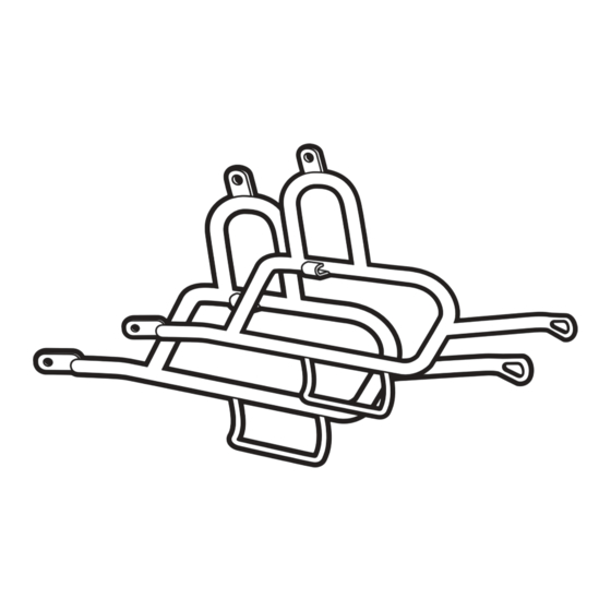
En los agarraderos laterales zona (A), posicionar las bridas (4L) y
(5L), según nos muestra el dibujo. Y en el lado derecho las bridas
(4R) y (5R). Nota: el lado izquierdo se mira montado sobre la moto.
A continuación montamos las chapas unión bridas (1) y las escuadras
bridas (2), realizaremos un conjunto y lo fijaremos mediante los
tornillos (3) y arandelas (6).
On the zone (A) side handles, positing the straps (4L) and (5L), as
shown in the diagram (showing the left side assembled on the
motorbike) and the straps on the right side (4R) and (5R). Then
attach the bodywork tightening straps (1) and the angle iron straps
(2), and assemble them all together tightening it together with the
screws (3) and the washers (6).
Dans les poignées latérales zone (A), positionner les brides (4L) et
(5L), tel qu'apparaît dans le dessin (on regarde le coté gauche monté
sur la moto) et dans le coté droit les brides (4R) et (5R). Ensuite
nous montons les plaques union brides (1) et les équerres brides (2),
nous formerons un ensemble et nous le fixerons avec les vis (3) et les
rondelles (6).
An den seitlichen Haltestangen der Zone (A), Flansche (4L) und (5L)
ansetzen, wie in der Zeichnung gezeigt wird (die linke Seite sieht man
am besten vom Motorradsitz aus) und auf der rechten Seite die
Flansche (4R) und (5R). Anschließend montieren Sie die
Verbindungsblech-Flansche (1) und die Winkel-Flansche (2), und
befestigen die Einheit mit Hilfe der Schrauben (3) und Scheiben (6).
Nei manici laterali zona (A), collocare le flangie (4L) e (5L), tale
quale ci mostra il dissegno (il lato sinistro si guarda montato nella
moto) e nel lato destro le flangie (4R) e (5R). In seguito montare le
lamiere unione flangie (1) e le squadre flangie (2), formare un
insieme e fissarlo con le viti (3) e rondelle (6).
Desmontaremos los intermitentes traseros (B) y cortaremos los cables
de conexión. Nota: Dejar unos 5 cm de cable en la zona próxima al
intermitente para facilitar después el montaje del alargador (17) y
luego mas tarde poder realizar la conexión de los soportes KIT SIDE
(7).
Take apart the back indicators (B) and cut the connection leads.
Note: Leave some 1 15/16" of cable in the area near the indicators to
help later the assembly of the extension lead (17) and then later to
connect the KIT SIDE supports (7).
Nous démonterons les clignotants arrières (B) et nous couperons les
câbles de connexion. Remarque: Laisser environ 5 cm de câble dans
la zone proche au clignotant pour faciliter après le montage de la
rallonge (17) et ensuite pouvoir effectuer la connexion des supports
KIT SIDE (7).
Nehmen Sie die hinteren Blinker (B) ab und schneiden die
Verbindungskabel durch. Anmerkung: Etwa 5 cm Kabel in der Nähe
des Blinkers lassen, um die nachfolgende Montage des
Verlängerungsstücks (17) und anschließend die Verbindung der
Stützvorrichtungen KIT SIDE (7) zu ermöglichen.
Smontare i lampeggiatori posteriori (B) e tagliare i cavi di
collegamento. Nota: Lasciare piú o meno 5 cm di cavo nella zona
vicina al lampeggiatore per agevolare dopo il montaggio della
prolunga (17) e dopo piú tardi potere realizzare il collegamento dei
supporti KIT SIDE (7).
Publicidad

Manuales relacionados para Shad Y0FZ64SF


Resumen de contenidos para Shad Y0FZ64SF
- Página 1 Consejo para un correcto montaje del kit: No apretar los tornillos del todo hasta asegurarse que el kit está correctamente colocacado y alineado. Nota: Si su moto ya posee el KIT TOP (Y0FZ64ST), deberá desestimar en este caso los tornillos (3), las cuatro arandelas (6), las chapas unión bridas (1), las escuadras bridas (2) y las bridas de plástico (4L) (4R) y (5L) (5R).
- Página 2 Montar los soportes KIT SIDE (7), en zona (C), por el interior de las estriberas mediante las arandelas (8), los tornillos (9), las arandelas (10) y las tuercas (11), y en zona (D), mediante los distanciadores (12), los tornillos (13) y las arandelas (10). Assemble the KIT SIDE supports (7), at zone (C), inside the foot pegs with the washers (8), the screws (9), the washers (10) and the nuts (11), and at zone (D), with the...
- Página 3 Una vez realizado esto, montaremos los intermitentes (B) y los ajustaremos mediante le junta de goma (18). Once you have done that, position the indicators (B) and adjust them through the rubber joint (18). Une fois ceci effectué, nous monterons les clignotants (B) et nous les ajusterons au moyen du joint en caoutchouc (18).