Tabla de contenido
Publicidad
Idiomas disponibles
Idiomas disponibles
Enlaces rápidos
Harbor Breeze® is a registered trademark of
LF, LLC. All Rights Reserved.
ATTACH YOUR RECEIPT HERE
Serial Number
Questions, problems, missing parts? Before returning to your retailer, call our
customer service department at 1-800-643-0067, 8 a.m. - 6 p.m., EST, Monday -
Thursday, 8 a.m. - 5 p.m., EST, Friday.
EB12185
Purchase Date
1
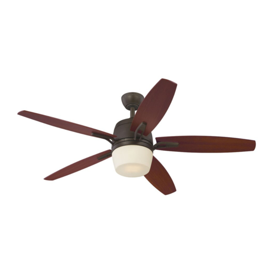
BATTLER CEILING FAN
MODEL #E-LUK52HBB5LEDR
Lowes.com/harborbreeze
ITEM #0206739
Español p. 20
3170356
Publicidad
Capítulos
Tabla de contenido
Solución de problemas

Manuales relacionados para Harbor Breeze E-LUK52HBB5LEDR


Resumen de contenidos para Harbor Breeze E-LUK52HBB5LEDR
- Página 1 ITEM #0206739 BATTLER CEILING FAN MODEL #E-LUK52HBB5LEDR Español p. 20 Harbor Breeze® is a registered trademark of LF, LLC. All Rights Reserved. ATTACH YOUR RECEIPT HERE 3170356 Serial Number Purchase Date Questions, problems, missing parts? Before returning to your retailer, call our customer service department at 1-800-643-0067, 8 a.m.
-
Página 2: Tabla De Contenido
TABLE OF CONTENTS Safety Information ........................2 Package Contents ........................4 Hardware Contents ........................5 Preparation ..........................5 Initial Installation ......................... 6 Fan Mounting ..........................7 Wiring ............................9 Final Installation ..........................11 Automated Learning Process/Activating Code ................14 Operating Instructions for Remote Control and Fan ..............15 Care and Maintenance .......................17... - Página 3 SAFETY INFORMATION WARNINGS To reduce the risk of fire, electrical shock, or personal injury, mount fan to outlet box marked "ACCEPTABLE FOR FAN SUPPORT OF 15.9 KG (35 LBS.) OR LESS" and use mounting screws provided with the outlet box. Most outlet boxes commonly used for the support of lighting fixtures are not acceptable for fan support and may need to be replaced.
-
Página 4: Package Contents
PACKAGE CONTENTS 12V Size A23 PART DESCRIPTION QUANTITY PART DESCRIPTION QUANTITY Canopy Mounting Screw Downrod (preassembled) Canopy Glass Shade Mounting Bracket Shade Fitter Yoke Cover Remote Control Motor Housing Transmitter Blade Arm 12-volt Battery Blade Fitter Plate Screw Light Kit (preassembled) Canopy Cover Shade Fitter Screw... -
Página 5: Hardware Contents
HARDWARE CONTENTS (shown actual size) Lock Blade Washer Fiber Motor Screw Blade Screw Qty. 10 E3 Wire Washer Qty. 15 Connector + 1 extra Qty. 10 + 1 extra Qty. 15 + 1 extra Qty. 4 + 1 extra PREPARATION Before beginning assembly of product, make sure all parts are present. -
Página 6: Initial Installation
INITIAL INSTALLATION Turn off circuit breakers and wall switch to the fan supply line leads. DANGER: Failure to disconnect power supply prior to installation may result in serious injury or death. Determine mounting method to use. A. Normal mount B. Angle mount IMPORTANT: If using the angle mount, check to make sure the ceiling angle is not steeper than 19°. -
Página 7: Important
INITIAL INSTALLATION Secure mounting bracket (C) to outlet box (not included) using screws, spring washers, and flat washers provided with the outlet box. *NOTE: It is very important that you use the proper hardware when installing the mounting bracket (C) as this will support the fan. - Página 8 FAN MOUNTING 2. Insert downrod (A) through canopy (B), canopy cover (I) and yoke cover (D). [NOTE: Canopy cover (I) must be turned with the shiny side toward the motor housing (E).] Thread wires from motor housing (E) through downrod (A). 3.
-
Página 9: Wiring
FAN MOUNTING If you decided to cut back the lead wires in Step 4, strip a 1/2 in. of insulation from end of white wire. Twist stripped ends of each strand of wire within the insulation with pliers. Repeat Step 5 for black, blue (if applicable) and green wires. - Página 10 WIRING [NOTE: For each wire connection below, and use one of the wire connectors (CC), making sure to BLACK screw wire connector (CC) on in a clockwise WHITE 120 V Power FROM direction.] CEILING GROUND/GREEN (BARE) Connect BLACK wire from fan to BLACK wire WHITE from ceiling.
-
Página 11: Final Installation
FINAL INSTALLATION Locate two canopy mounting screws (L) on underside of mounting bracket (C) and remove canopy mounting screw (L) closest to the open end of the mounting bracket (C). Partially loosen the other canopy mounting screw (L). Lift canopy (B) to mounting bracket (C). - Página 12 FINAL INSTALLATION 4. Remove one fitter plate screw (Q) from fitter plate (on underside of motor) and loosen the other two fitter plate screws (Q). Align slotted holes in middle of shade fitter (N) with loosened fitter plate screws (Q), allowing male plug from motor housing (E) to come through hole in middle of shade fitter (N).
- Página 13 FINAL INSTALLATION Align holes in light kit (H) with holes in shade fitter (N). Re-insert shade fitter screws (R) that were previously removed. Securely tighten all three shade fitter screws (R) but do NOT overtighten shade fitter screws (R) as protective cover on light kit (H) may crack or break.
-
Página 14: Automated Learning Process/Activating Code
AUTOMATED LEARNING PROCESS/ACTIVATING CODE CAUTION: The remote control transmitter (O) can be programmed to multiple receivers or fans. If this is not desired, turn wall switch off to any other programmable receiver or fan. Remove battery cover from back side of remote Code Switches control transmitter (O). -
Página 15: Operating Instructions For Remote Control And Fan
AUTOMATED LEARNING PROCESS/ACTIVATING CODE Modifications not approved by the party responsible for compliance could void the user's authority to operate the equipment. *NOTE: This equipment has been tested and found to comply with the limits for a Class B digital device, pursuant to Part 15 of the FCC Rules. - Página 16 OPERATING INSTRUCTIONS FOR REMOTE CONTROL AND FAN 2. Lift the yoke cover (D) in order to use the fan reverse switch, located on top of the motor housing (E), to optimize your fan for seasonal performance. A ceiling fan will allow you to raise your thermostat setting in summer and lower your thermostat setting in winter without feeling a difference in your comfort.
-
Página 17: Care And Maintenance
CARE AND MAINTENANCE At least twice each year, lower canopy (B) to check downrod (A) assembly, and then tighten all screws on the fan. Clean motor housing (E) with only a soft brush or lint-free cloth to avoid scratching the finish. Clean blades (G) with a lint-free cloth. You may occasionally apply a light coat of furniture polish to wood blades for added protection. -
Página 18: Warranty
TROUBLESHOOTING PROBLEM POSSIBLE CAUSE CORRECTIVE ACTION 7. Carefully loosen and lower 7. Set screw on hanging ball is not canopy (B) and verify that set tightened properly. screw on hanging ball is tightened securely. Fan operates but 1. Wires in canopy (B) not wired 1. -
Página 19: Replacement Parts List
Canopy Mounting Screw Glass Shade Shade Fitter Fitter Plate Screw Shade Fitter Screw Blade Screw Fiber Blade Washer E3 Wire Connector Motor Screw Lock Washer Printed in China Harbor Breeze® is a registered trademark of LF, LLC. All Rights Reserved. Lowes.com/harborbreeze LI1208... -
Página 20: Adjunte Su Recibo Aquí
ARTÍCULO #0206739 VENTILADOR DE TECHO BATTLER MODELO #E-LUK52HBB5LEDR ® Harbor Breeze es una marca registrada de LF, LLC. Todos los derechos reservados. ADJUNTE SU RECIBO AQUÍ 3170356 Número de serie Fecha de compra ¿Preguntas, problemas, piezas faltantes? Antes de volver a la tienda, llame a nuestro Departamento de Servicio al Cliente al 1-800-643-0067 de lunes a jueves de 8 a. - Página 21 ÍNDICE Información de seguridad.........................21 Contenido del paquete........................23 Aditamentos.............................24 Preparación............................24 Instalación inicial..........................25 Montaje del ventilador........................26 Cableado............................28 Instalación final..........................30 Proceso de aprendizaje automatizado/código de activación............33 Instrucciones de funcionamiento para control remoto y el ventilador..........34 Cuidado y mantenimiento.........................36 Solución de problemas........................36 Garantía............................37 Lista de piezas de repuesto......................38 INFORMACIÓN DE SEGURIDAD LEA Y GUARDE ESTAS INSTRUCCIONES Lea y comprenda completamente este manual antes de intentar ensamblar, instalar o usar el producto.
-
Página 22: Información De Seguridad
INFORMACIÓN DE SEGURIDAD ADVERTENCIAS Para reducir el riesgo de incendios, descargas eléctricas o lesiones personales, monte el ventilador en una caja de salida marcada como APTA PARA SOSTENER VENTILADORES DE 15,88 KG (35 LBS) O MENOS y utilice los tornillos de montaje que se proporcionan con la caja de salida. -
Página 23: Contenido Del Paquete
CONTENIDO DEL PAQUETE 12 V Tamaño A23 PIEZA DESCRIPCIÓN CANTIDAD PIEZA DESCRIPCIÓN CANTIDAD Tornillo de montaje de la base Varilla (preensamblado) Base Pantalla de vidrio Soporte de montaje Soporte de la pantalla Cubierta de la horquilla Control remoto Carcasa del motor Transmisor Brazo del aspa Batería de 12 voltios... -
Página 24: Aditamentos
ADITAMENTOS (se muestran en tamaño real) Arandela de Tornillo seguridad Arandela para Tornillo del para aspa aspa de fibra motor Cant. 10 Conector de Cant. 15 + 1 adicional cables E3 Cant. 15 Cant. 10 + 1 adicional + 1 adicional + 1 adicional Cant. -
Página 25: Instalación Inicial
INSTALACIÓN INICIAL Interrumpa el suministro de energía del ventilador apagando los interruptores de circuito y el interruptor de pared. PELIGRO: Si no desconecta el suministro de electricidad antes de la instalación, pueden producirse lesiones graves o la muerte. Determine el método de montaje que utilizará. A. -
Página 26: Importante
INSTALACIÓN INICIAL Asegure el soporte de montaje (C) a la caja de salida (no se incluye) con los tornillos, las arandelas de resorte y las arandelas planas provistas con la caja de salida. *NOTA: Es muy importante que use los aditamentos adecuados para instalar el soporte de montaje (C), ya que este sostendrá... - Página 27 MONTAJE DEL VENTILADOR 2. Introduzca la varilla (A) a través de la base (B), la cubierta de la base (I) y la cubierta de la horquilla (D). [NOTA: La cubierta de la base (I) debe girarse con el lado brillante apuntando hacia la carcasa del motor (E)].
-
Página 28: Cableado
MONTAJE DEL VENTILADOR Si decidió cortar los cables conductores en el Paso 4, pele 1,27 cm del aislamiento del extremo del conductor blanco. Usando unas pinzas, tuerza los extremos pelados de cada filamento de conductor al interior del aislamiento. Repita el Paso 5 para los conductores negro, azul (si corresponde) y verde. - Página 29 CABLEADO [NOTA: Para cada conexión de cables a continuación, utilice uno de los conectores de cables (CC) provistos, NEGRO asegurándose de atornillar el conector de cable (CC) Alimentación de BLANCO 120 V DESDE en dirección de las manecillas del reloj]. EL TECHO DE PUESTA A TIERRA/VERDE (DESNUDO) Conecte el conductor NEGRO del ventilador al...
-
Página 30: Instalación Final
INSTALACIÓN FINAL Ubique los dos tornillos de montaje de la base (L), debajo del soporte de montaje (C), y retire el tornillo de montaje de la base (L) más cercano al extremo abierto del soporte de montaje (C). Afloje parcialmente el otro tornillo de montaje de la base (L). - Página 31 INSTALACIÓN FINAL 4. Retire un tornillo de la placa de soporte (Q) de la placa de soporte (en la parte inferior del motor) y afloje los otros dos tornillos de la placa de soporte (Q). Alinee los orificios ranurados en el centro del soporte de la pantalla (N) con los tornillos aflojados de la placa de soporte (Q), permitiendo que el enchufe macho de la carcasa...
- Página 32 INSTALACIÓN FINAL Alinee los orificios del kit de iluminación (H) con los orificios del soporte de la pantalla (N). Vuelva a insertar los tornillos del soporte de la pantalla (R) que retiró anteriormente. Apriete firmemente los tres tornillos del soporte de la pantalla (R) pero NO los apriete demasiado, ya que la cubierta protectora del kit de iluminación (H) puede partirse o romper.
-
Página 33: Proceso De Aprendizaje Automatizado/Código De Activación
PROCESO DE APRENDIZAJE AUTOMATIZADO/CÓDIGO DE ACTIVACIÓN PRECAUCIÓN: El transmisor del control remoto (O) se puede programar para varios receptores o ventiladores. Si usted no desea hacer esto, desactive el interruptor de pared para cualquier otro receptor o ventilador programable. Retire la cubierta de la batería desde la parte Interruptores de código posterior del transmisor del control remoto (O). -
Página 34: Instrucciones De Funcionamiento Para Control Remoto Y El Ventilador
PROCESO DE APRENDIZAJE AUTOMATIZADO/CÓDIGO DE ACTIVACIÓN Las modificaciones que no estén aprobadas por la parte responsable del cumplimiento podrían anular la autorización del usuario para utilizar el equipo. *NOTA: Este equipo ha sido probado y se ha verificado que cumple los límites para un dispositivo digital clase B, conforme a la sección 15 de las reglas de la FCC. - Página 35 INSTRUCCIONES DE FUNCIONAMIENTO PARA EL CONTROL REMOTO Y EL VENTILADOR 2. Levante la cubierta de la horquilla (D) para usar el interruptor de reversa del ventilador, ubicado en la parte superior de la carcasa del motor (E), para optimizar el rendimiento del ventilador por temporada.
-
Página 36: Cuidado Y Mantenimiento
CUIDADO Y MANTENIMIENTO Al menos dos veces al año, baje la base (B) para revisar el ensamble de la varilla (A) y luego apriete todos los tornillos del ventilador. Limpie la carcasa del motor (E) solo con un cepillo suave o un paño que no produzca pelusas para evitar rayar el acabado. -
Página 37: Garantía Limitada De Por Vida
SOLUCIÓN DE PROBLEMAS PROBLEMA CAUSA POSIBLE ACCIÓN CORRECTIVA 7. Afloje y baje cuidadosamente la base (B) 7. El tornillo de fijación en la bola para y verifique que el tornillo de fijación en la colgar no está bien apretado. bola para colgar esté bien apretado. El ventilador 1. -
Página 38: Lista De Piezas De Repuesto
Tornillo del soporte de la pantalla Tornillo para aspa Arandela para aspa de fibra Conector de cables E3 Tornillo del motor Arandela de seguridad Impreso en China ® Harbor Breeze es una marca registrada de LF, LLC. Todos los derechos reservados. Lowes.com/harborbreeze LI1208...