Tabla de contenido
Publicidad
Idiomas disponibles
Idiomas disponibles
Enlaces rápidos
Publicidad
Capítulos
Tabla de contenido

Manuales relacionados para Metrix MX 670


Resumen de contenidos para Metrix MX 670
- Página 1 Pince Multimètre Multimeter Clamp Multimeterzange Pinza Multimetro Pinza Multímetro 670 / 675 F R AN Ç AI S Notice de fonctionnement E N G L I S H User’s manual D E U T C H Bedienungsanleitung I T A L I A N O Manuale d’uso...
-
Página 2: Tabla De Contenido
TABLE DES MATIERES INSTRUCTIONS GENERALES ...... 3 ..........3 ÉBALLAGE MBALLAGE .... 3 RÉCAUTIONS ET SÉCURITÉ DANS LES MESURES DESCRIPTION DE L’INSTRUMENT ...... 6 ........6 ESCRIPTION DE LA FACE AVANT ’ LCD ......7 ESCRIPTION DE L AFFICHEUR DESCRIPTION GENERALE ...... -
Página 3: Instructions Generales
English -------------------------------------------------------------- 20 Deutsch ------------------------------------------------------------- 37 Italiano --------------------------------------------------------------- 55 Espanol -------------------------------------------------------------- 72 Vous venez d'acquérir une pince multimètre MX670 ou MX675 et nous vous remercions de votre confiance. Pour obtenir le meilleur service de votre appareil : lisez attentivement cette notice de fonctionnement, ... -
Página 4: Signification Des Symboles Utilisés
Pour des raisons de sécurité, vous devez utiliser uniquement des cordons de mesure, de tension et catégorie au moins égales à celles de l'instrument et conformes à la norme IEC 61010. Avant utilisation, toujours vérifier l'intégrité du boîtier de l'instrument et des isolants des cordons. 1.2.2 Signification des symboles utilisés Symbole Signification... - Página 5 • Utilisez l’appareil uniquement comme il est précisé dans cette notice ; sinon, la protection fournie par ce multimètre peut être altérée. • N’utilisez pas cet appareil s’il semble endommagé. • Inspectez l'intégrité de l'isolation des cordons. Remplacez les cordons endommagés. •...
-
Página 6: Description De L'INstrument
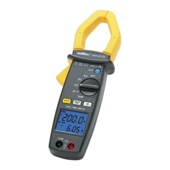
DESCRIPTION DE L’INSTRUMENT Description de la face avant Mâchoires Gâchette Commutateur Bouton HOLD Bouton A Zero&HOLD Touche DISPLAY Touche MIN MAX PEAK Touche BACKLIGHT Afficheur LCD Entrée douille COM Entrée douille + Garde physique MX670 / MX675... -
Página 7: Escription De Lafficheur Lcd
Description de l’afficheur LCD MX670 MX675 Arrêt automatique Valeur Max. Valeur Min. Test de Continuité HOLD Gel de l’affichage Ω Mesure de Résistance Mesure de Tension ... -
Página 8: Description Generale
DESCRIPTION GENERALE Correction du zéro en mesure de courant continu Cette fonction n'est présente que sur le modèle MX675 pour ramener à zéro l'affichage de l'aimantation rémanente de la pince en mesure de courant continu. Lorsque le commutateur est positionné sur A et en absence de tout conducteur enserré... -
Página 9: Fonction Min Max (500 Ms)
Fonction MIN MAX (500 ms) Pour activer la fonction MIN MAX, appuyer sur la touche MIN MAX PEAK. La valeur MIN est alors affichée. (le symbole MIN est affiché et fixe, le symbole MAX est affiché et clignotant) En appuyant à nouveau sur la touche, la valeur MAX sera affichée (le symbole MIN est affiché... -
Página 10: Mesure De Tension Continue
Mesure de Tension continue • Positionner le commutateur sur V . Connecter cordon mesure rouge sur la borne "+" et le cordon de mesure noir sur la borne "COM". Mettre les pointes de touche en contact avec les points à mesurer sous tension DC. -
Página 11: Mesure De Courant Continu (Mx675 Seulement)
Mesure de Courant continu (MX675 seulement) Positionner le commutateur sur Une fois l’affichage stabilisé, appuyer sur le bouton A ZERO & HOLD pour ramener l'affichage à zéro. La procédure de fonctionnement est ensuite identique à celle de la mesure de courant alternatif. Voir paragraphe précédent. -
Página 12: Test Sonore De Continuité
4.5.2 Test sonore de continuité: Connecter le cordon de mesure rouge sur la borne "+" et le cordon de mesure noir sur la borne "COM". Mettre les pointes de touche en contact avec le circuit à tester. Si la valeur de la résistance du circuit R<35Ω, le buzzer sonne en continu. -
Página 13: Mesure De La Fréquence En Tension
Mesure de la Fréquence en tension Positionner le commutateur sur V , et appuyer sur la touche DISPLAY. Connecter cordon mesure rouge sur la borne "+" et le cordon de mesure noir sur la borne "COM". Mettre les pointes de touche en contact avec les points où... -
Página 14: Specifications Techniques
SPECIFICATIONS TECHNIQUES Généralités Les tolérances assignées aux valeurs, ou les limites déclarées, constituent seulement les valeurs garanties par le fabricant. Les valeurs sans tolérances sont données à titre indicatif. Le symbole est affiché lorsque les signaux d’entrée excèdent les valeurs limites possibles dans chaque gamme de mesure. - Página 15 5.2.5 Résistance (Ω) Etendue de Gamme Résolution Précision mesure Ω Ω Ω 1% ± 3cts 1000 0.0 to 999.9 Ω Ω Ω 10000 1000 to 9999 3.3 V (Vmax) Protection: 1 000 Veff 5.2.6 Continuité Gamme Etendue de mesure Précision 1% ±...
-
Página 16: Sécurité Électrique (Selon Nf En 61010)
Sécurité électrique (selon NF EN 61010) : Conforme aux normes de sécurité NF EN 61010-1 et NF EN 61010-2-032 pour 600 V CAT IV ou 1000V CAT III, degré de Pollution 2 et altitude < 2000 m. Informations générales Affichage numérique : LCD double affichage 4 digits avec lecture maxi de 9999 points. -
Página 17: Compatibilité Électromagnétique
5.5.3 Compatibilité électromagnétique (selon NF EN 61326-1) Conforme à la norme de compatibilité électromagnétique NF EN 61326-1 Emission rayonnée et conduite (NF EN 55022) Immunité rayonnée, critère B (NF EN 61000-4-3) Immunité conduite, critère A (NF EN 61000-4-6) Décharges électrostatiques, critère A (NF EN 61000-4-2) Transitoires, critère B (NF EN 61000-4-4) Ondes de choc, critère A (NF EN 61000-4-5) -
Página 18: Nettoyage
Fax : 02 31 64 51 09 Réparation sous garantie et hors garantie Adressez vos appareils à l'un des Centres Techniques régional Manumesure agréé Chauvin-Arnoux Metrix. Renseignements et coordonnées sur demande : Tél : 02 31 64 51 43 Fax : 02 31 64 51 09 ou renvoyer l’instrument à... -
Página 19: Pour Commander
POUR COMMANDER MX 670 Pince Multimètre ....... MX0670 MX 675 Pince Multimètre ....... MX0675 Livré avec : • 1 jeu de cordons avec pointe de touche (rouge et noir), • 1 notice de fonctionnement 5 langues, • 1 pile alcaline 9V. - Página 20 TABLE OF CONTENTS GENERAL INSTRUCTIONS ........21 – P ..........21 NPACKING ACKING .... 21 RECAUTIONS AND SAFETY IN MEASUREMENTS DESCRIPTION OF THE INSTRUMENT ....23 ......23 ESCRIPTION OF THE FRONT PANEL ........24 ESCRIPTION OF DISPLAY GENERAL DESCRIPTION ........25 ....
-
Página 21: General Instructions
Thank you for purchasing this MX670 or MX675 series multimeter clamp. To obtain the best service from your unit: read these operating instructions carefully, comply with the precautions for use. GENERAL INSTRUCTIONS If the device is used in a manner unspecified in these instructions, the protection provided by the device may be compromised. -
Página 22: Meaning Of Symbols Used
1.2.2 Meaning of symbols used Symbol Meaning Symbol Meaning Instrument protected Ground. by double isolation. Alternating current. Battery. The CE marking guarantees conformity with Direct current. European directives and with regulations covering EMC. CAUTION - Selective sorting DANGER! Refer to of waste for the operating manual. -
Página 23: Description Of The Instrument
• Always use the type of battery specified. • Before opening the instrument, disconnect it from the measurement circuits, switch off and make sure you are not charged with static electricity, which would irreversibly damage the internal components of the instrument. DESCRIPTION OF THE INSTRUMENT Description of the front panel Jaws... -
Página 24: Description Of Lcd Display
Description of LCD display MX670 MX675 Auto power-off Max. value MIN value Continuity Test HOLD Freeze display Ω Resistance measurement Voltage measurement Current measurement ... -
Página 25: General Description
GENERAL DESCRIPTION Correction of zero in DC measurement This function is present only on model MX675 to return to zero the display of the remanent magnetization of the clamp in DC measurement. When the switch is positioned on A and with no conductor inserted into the clamp, press the A ZERO &... -
Página 26: Max Min Function (500 Ms)
MAX MIN function (500 ms) To activate the MAX MIN function, press on the MIN MAX PEAK button. The MIN value is then displayed. (the MIN symbol is displayed steady; the MAX symbol is displayed flashing) By pressing again on the key, the MAX value will be displayed (the MIN symbol is displayed flashing;... -
Página 27: Dc Voltage Measurement
DC voltage measurement • Position the switch on V . Connect the red test lead to the "+" terminal and the black test lead "COM" terminal. Put the touch prods in contact with the measurement points under DC voltage. Read result measurement on the display. -
Página 28: Dc Current Measurement (Mx675 Only)
DC Current measurement (MX675 only) Set the switch to A Once the display is stabilised, press the A ZERO & HOLD button to reset the display to zero. The operating procedure is then identical that measurement. See previous paragraph. Note: The correct display of current direction is the result of observing the positioning of the "+"... -
Página 29: Audio Continuity Test
4.5.2 Audio Continuity Test: Connect the red test lead to the "+" terminal and the black test lead to the "COM" terminal. Put the touch prods into contact with the circuit to be tested. If the resistance value of circuit R<35 Ω, the buzzer sounds continuously. -
Página 30: Measurement Of Voltage Frequency
Measurement of voltage frequency Position the switch on V and press the DISPLAY key. Connect the red test lead to the "+" terminal and the black test lead "COM" terminal. Place the touch prods in contact with the points whose frequency is to be measured. -
Página 31: Technical Specifications
TECHNICAL SPECIFICATIONS General The tolerances assigned to the values, or declared limits, constitute only the values guaranteed by the manufacturer. Values without a tolerance are for information only. The symbol is displayed when the input signals exceed the limit values possible in each measurement range. The symbol is displayed in °C/°F measurement when there is no input signal (open circuit). -
Página 32: Electrical Safety (As Per Nf En 61010)
5.2.6 Continuity Range Measuring range Accuracy 1% ± 3 cts Ohm Function Continuity Ω Buzzer < 35 3.3 V (Vmax) Protection: 1,000 Vrms 5.2.7 Frequency Hz • For currents Measuring Range Resolution Accuracy Sensitivity range 1,000H 0.0 to 999.9 Hz 0.1 Hz 1.0% ±... -
Página 33: General Information
General information Digital display: LCD dual display, 4 digits with max. indication of 9999 points. Polarity: When a negative signal is applied, the sign appears. Low Battery Indicator: is displayed when the voltage supplied by the battery is lower than the operating voltage. The measurements are then guaranteed for only a short period. -
Página 34: Maintenance
5.5.3 Electromagnetic Compatibility (as per NF EN 61326-1) Compliant with electromagnetic compatibility standard NF EN 61326-1 Radiated and conducted emission (NF EN 55022) Radiated Immunity, criterion B (NF EN 61000-4-3) Conducted Immunity, criterion A (NF EN 61000-4-6) Electrostatic discharges, criterion A (NF EN 61000-4-2) Transients, criterion B (NF EN 61000-4-4) Shock waves, criterion A (NF EN 61000-4-5) Note: Certain high power radioelectric frequencies are, in... -
Página 35: Cleaning
Tel.: 02 31 64 51 43 Fax: 02 31 64 51 09 Repairs under guarantee and outside guarantee Send your devices to one of the Chauvin-Arnoux Metrix- approved Manumesure regional technical centres. Information and address details available on request: Tel.: 02 31 64 51 43... - Página 36 TO ORDER MX 670 Multimeter Clamp ...... MX0670 MX 675 Multimeter Clamp ...... MX0675 Delivered with: • 1 set of leads with probe tip (red and black), • 1 user manual 5 languages, • 1 9V alkaline battery. • 1 supple carrying case.
- Página 37 INHALTSVERZEICHNIS ALLGEMEINE HINWEISE ........38 ......... 38 USPACKEN ERPACKEN ORSICHTS ICHERHEITSMAßNAHMEN BEI DEN .............. 38 ESSUNGEN BESCHREIBUNG DES GERÄTS ......41 ......41 ESCHREIBUNG DER ORDERSEITE LCD-A ......42 ESCHREIBUNG DER NZEIGE ALLGEMEINE BESCHREIBUNG ......43 ULLPUNKTKORREKTUR BEI LEICHSTROMMESSUNGEN HOLD – H ....
-
Página 38: Allgemeine Hinweise
WIR DANKEN IHNEN FÜR DAS VERTRAUEN, DASS SIE UNS MIT DEM KAUF EINER MULTIMETERZANGE MX670 ODER MX675 ENTGEGENGEBRACHT HABEN. Damit die optimale Nutzung des Geräts gewährleistet ist: lesen diese Bedienungsanleitung sorgfältig durch, beachten Sie die Sicherheitshinweise. ALLGEMEINE HINWEISE Wenn das Gerät auf eine nicht in dieser Bedienungsanleitung angegebene Weise verwendet wird, kann der ansonsten sichergestellte Schutz beeinträchtigt werden. -
Página 39: Bedeutung Der Zeichen Und Symbole
Überprüfen Sie vor der Benutzung immer die Unversehrtheit des Gerätegehäuses und die Isolation der Leitungen. 1.2.2 Bedeutung der Zeichen und Symbole Symbol Bedeutung Symbol Bedeutung Das Gerät ist Erde. schutzisoliert. Batterie oder Wechselstrom. Akku. Die CE- Kennzeichnung garantiert die Einhaltung der Gleichstrom. - Página 40 • Verwenden Sie das Gerät nicht, wenn es Anzeichen für eine Beschädigung gibt. • Überprüfen Isolation Leitungen Unversehrtheit. Tauschen Sie beschädigte Leitungen aus. • Seien Sie vorsichtig, wenn Sie mit Spannungen größer als 70 V oder 33 Veff und 46,7 Vpp arbeiten. Bei solchen Spannungen besteht...
-
Página 41: Beschreibung Des Geräts
BESCHREIBUNG DES GERÄTS Beschreibung der Vorderseite Backen Zuhaltung Wahlschalter Taste HOLD Taste A Zero & HOLD Taste DISPLAY Taste MIN MAX PEAK Taste BACKLIGHT LCD-Anzeige Eingangsbuchse COM Eingangsbuchse + Physische Schutzvorrichtung MX670 / MX675... -
Página 42: Beschreibung Der Lcd-Anzeige
Beschreibung der LCD-Anzeige MX670 MX675 Automatische Abschaltung MAX-Wert MIN-Wert Durchgangsprüfung HOLD Halten der Anzeige Ω Widerstandsmessung Spannungsmessung Strommessung Frequenzmessung Batterie oder Akku schwach ... -
Página 43: Allgemeine Beschreibung
ALLGEMEINE BESCHREIBUNG Nullpunktkorrektur bei Gleichstrommessungen Diese Funktion ist nur beim Modell MX675 vorhanden und dient dazu, die Anzeige der Remanenzmagnetisierung der Zange bei Gleichstrommessung auf null zu setzen. Wenn sich der Wahlschalter in der Position A befindet und die Zange keinen Leiter umfasst, die Taste A ZERO &... -
Página 44: Funktion Min Max (500 Ms)
ZERO & HOLD (MX675) bzw, die Taste HOLD (MX670) zwei Mal drücken; die Zange kehrt in den Normalbetrieb zurück. Funktion MIN MAX (500 ms) Zur Aktivierung der Funktion MIN MAX die Taste MIN MAX PEAK drücken. Der Wert MIN wird angezeigt (das Symbol MIN wird dauerhaft angezeigt und das Symbol MAX blinkt). -
Página 45: Gleichspannungsmessung
Gleichspannungsmessung • Stellen Wahlschalter auf V . Schließen rote Messleitung Eingangsbuchse "+" und die schwarze Messleitung an die Eingangsbuchse "COM" an. Berühren Prüfspitzen Punkte, zwischen denen messende Gleichspannung anliegt. Lesen Sie das Ergebnis der Messung auf der Anzeige ab. Beim Modell MX670 gibt es keine Sekundäranzeige für den Strom. - Página 46 Gleichstrommessung (nur MX675) Stellen Sie den Wahlschalter auf A . Drücken Sie, sobald sich die Anzeige stabilisiert hat, Taste A ZERO & HOLD, um die Anzeige auf null zu setzen. Der weitere Ablauf ist identisch Messung Wechselströmen. Siehe Abschnitt oben. Hinweis: Die richtige Anzeige der Stromrichtung erhalten Sie, wenn...
-
Página 47: Durchgangsprüfung
4.5.2 Akustische Durchgangsprüfung Schließen Sie die rote Messleitung an die Eingangsbuchse "+" und die schwarze Messleitung an die Eingangsbuchse "COM" an. Berühren Sie mit den Prüfspitzen den zu messenden Kreis. Ist der Widerstand des Kreises R < 35 Ω, gibt der Summer ein Dauersignal ab. -
Página 48: Frequenzmessung Bei Spannungen
Frequenzmessung bei Spannungen Stellen Sie den Wahlschalter auf V und drücken Sie die Taste DISPLAY. Schließen rote Messleitung Eingangsbuchse "+" und die schwarze Messleitung an die Eingangsbuchse "COM" an. Berühren Prüfspitzen die Punkte, an denen Frequenz gemessen werden soll. Lesen Sie die Frequenz auf der Sekundäranzeige ab. -
Página 49: Technische Angaben
TECHNISCHE ANGABEN Allgemeines Die angegebenen Toleranzen und Grenzwerte stellen nur die vom Hersteller garantierten Werte dar. Die ohne Toleranzen angegebenen Werte dienen nur zur Information. Das Symbol wird angezeigt, wenn ein Eingangssignal den möglichen Grenzwert eines Bereichs überschreitet. Das Symbol wird bei Messungen °C/°F angezeigt, wenn kein Eingangssignal vorliegt (offener Kreis). - Página 50 5.2.5 Widerstand (Ω) Bereich Messumfang Auflösung Genauigkeit Ω Ω Ω 1 % ± 1000 0.0 bis 999.9 Digits Ω Ω Ω 10000 1000 bis 9999 3.3 V (Vmax) Schutz: 1 000 Veff 5.2.6 Durchgang Bereich Messumfang Genauigkeit 1 % ± 3 Digits Funktion Ohm Durchgang Ω...
-
Página 51: Elektrische Sicherheit (Gemäß Nf En 61010)
Elektrische Sicherheit (gemäß NF EN 61010): Einhaltung der Sicherheitsnormen NF EN 61010-1 und NF EN 61010-2-032 für 600 V CAT IV oder 1000V CAT III, Verschmutzungsgrad 2 und Höhe < 2000 m. Allgemeine Informationen Digitalanzeige: Doppelte LCD-Anzeige, 4 Digits mit max. Anzeige von 9999 Punkten. -
Página 52: Wartung
5.5.3 Elektromagnetische Verträglichkeit (gemäß NF EN 61326-1) Entspricht der Norm zur elektromagnetischen Verträglichkeit NF EN 61326-1 Strahlungs- und Leitungsemission (NF EN 55022) Strahlungsimmunität, Kriterium B (NF EN 61000-4-3) Leitungsimmunität, Kriterium A (NF EN 61000-4-6) Elektrostatische Entladungen, Kriterium A (NF EN 61000-4-2) Transiente Störgrößen, Kriterium B (NF EN 61000-4-4) Stoßwellen, Kriterium A (NF EN 61000-4-5) Hinweis: Einige Funkfrequenzen hoher Leistung können... -
Página 53: Reinigung
Informationen und Anschriften erhalten Sie auf Anfrage: Tel.: 02 31 64 51 43 Fax: 02 31 64 51 09 Reparaturen innerhalb und außerhalb der Garantie Senden Sie Ihre Geräte an eine der von CHAUVIN ARNOUX METRIX zugelassenen regionalen Technik-Center MANUMESURE. - Página 54 BESTELLANGABEN MX 670 Multimeterzange ......MX0670 MX 675 Multimeterzange ......MX0675 Lieferumfang : • 1 Satz Prüfdrähte mit Tastspitze (rot und schwarz), • 1 Bedienungsanleitung 5 Sprachen, • 1 Alkali-Akku 9V. • 1 Geldbeutel Geschmeidiger Beförderung . • 1 Kabel Thermoelement K.
- Página 55 INDICE ISTRUZIONI GENERALI ......... 56 ..........56 BALLARE MBALLARE ....56 RECAUZIONI E SICUREZZA NELLE MISURE DESCRIZIONE DELLO STRUMENTO ....58 ......58 ESCRIZIONE DEL LATOANTERIORE LCD ......... 59 ESCRIZIONE DEL DISPLAY DESCRIZIONE GENERALE ........60 ORREZIONE DELLO ZERO IN MISURA DI CORRENTE ..............
-
Página 56: Istruzioni Generali
Avete appena acquistato una pinza multimetro MX670 o MX675 e vi ringraziamo per la vostra fiducia. Per ottenere il migliore servizio dal vostro apparecchio: leggere attentamente le presenti istruzioni per l’uso. rispettare le precauzioni d’uso. ISTRUZIONI GENERALI Se l'apparecchio viene utilizzato in modo non specificato nel presente manuale d’uso,... -
Página 57: Significato Dei Simboli Utilizzati
1.2.2 Significato dei simboli utilizzati Simbolo Significato Simbolo Significato Strumento protetto da Terra. doppio isolamento. Corrente alternata. Pila o batteria Il marchio CE garantisce conformità alle direttive europee Corrente continua. ed anche alle regolamentazioni nel campo di CEM. Attenzione, rischio e Classificazione pericolo. -
Página 58: Descrizione Dello Strumento
• Tenere la mano sempre dietro la protezione fisica dei puntali o della pinza durante una operazione di misura. • Utilizzare sempre il tipo di pila o di batteria specificato. • Prima di aprire lo strumento, scollegarlo dai circuiti di misura, spegnerlo e verificare di non essere caricato di elettricità... -
Página 59: Descrizione Del Display Lcd
Descrizione del display LCD MX670 MX675 Arresto automatico Valore Max Valore Min Test di Continuità HOLD Blocco del display Ω Misura di Resistenza Misura di Tensione ... -
Página 60: Descrizione Generale
DESCRIZIONE GENERALE Correzione dello zero in misura di corrente continua Questa funzione è presente solo sul modello MX675 per azzerare la visualizzazione dell’alimentazione permanente della pinza in misura di corrente continua. Quando il commutatore è posizionato su A ed, in assenza di un conduttore stretto nella pinza, premere sul tasto A ZERO &... -
Página 61: Funzione Min Max (500 Ms)
Per uscire da questa funzione, premere sul tasto MIN MAX PEAK per lo meno per 2 secondi o premere sul pulsante A ZERO & HOLD (MX675) 2 volte o premere sul pulsante HOLD (MX670) 2 volte ; la Pinza ritorna nel modo normale. Funzione MIN MAX (500 ms) Per attivare la funzione MIN MAX , premere sul tasto MIN MAX PEAK. -
Página 62: Misura Di Tensione Continua
Misura di Tensione continua • Posizionare il commutatore su V . Collegare il cavo di misura rosso sul morsetto "+" ed il cavo di misura nero sul morsetto "COM". Mettere i puntali in contatto con i punti da misurare in tensione DC. -
Página 63: Misura Di Corrente Continua (Mx675 Solo)
Misura di Corrente continua (MX675 solo) Posizionare il commutatore su Dopo la stabilizzazione della visualizzazione, premere pulsante A ZERO & HOLD per azzerare la visualizzazione. La procedura di funzionamento è in seguito identica a quella della misura corrente alternativa. Vedere paragrafo precedente. Nota : visualizzazione corretta del senso di passaggio... -
Página 64: Misura Di Temperatura °C/°F
4.5.2 Test sonoro di continuità: Collegare il cavo di misura rosso sul morsetto "+" ed il cavo di misura nero sul morsetto "COM" . Mettere i puntali a contatto del circuito da testare. Se il valore della resistenza del circuito R<35 Ω, il buzzer suona in continuo . -
Página 65: Misura Della Frequenza In Tensione
Misura della Frequenza in tensione Posizionare il commutatore su , e premere sul tasto DISPLAY . Collegare il cavo di misura rosso sul morsetto "+" ed il cavo misura nero morsetto "COM". Mettere i puntali in contatto con i punti dove si desidera misurare la frequenza. -
Página 66: Specifiche Tecniche
SPECIFICHE TECNICHE Generalità Le tolleranze assegnate ai valori, o i limiti dichiarati, costituiscono i valori garantiti dal fabbricante. I valori senza tolleranze sono dati a titolo indicativo . Il simbolo è visualizzato quando i segnali d’entrata superano i valori limite possibili in ogni gamma di misura. Il simbolo è... - Página 67 5.2.5 Resistenza (Ω) Gamma Campo di misura Risoluzione Precisione Ω Ω Ω 1% ± 3cts 1000 0.0 to 999.9 Ω Ω Ω 10000 1000 to 9999 3.3 V (Vmax) Protezione: 1 000 Veff 5.2.6 Continuità Gamma Campo di misura Precisione 1% ±...
-
Página 68: Sicurezza Elettrica (Secondo Nf En 61010)
Sicurezza elettrica (secondo NF EN 61010) : Conforme alle norme di sicurezza NF EN 61010-1 NF EN 61010-2-032 per 600 V CAT IV o 1000V CAT III, livello di Inquinamento 2 ed altitudine < 2000 m. Informazioni generali Visualizzazione numerica : LCD doppia visualizzazione 4 digit con lettura maxi di 9999 punti. -
Página 69: Compatibilità Elettromagnetica
5.5.3 Compatibilità elettromagnetica (secondo NF EN 61326-1) Conforme alla norma di compatibilità elettromagnetica NF EN 61326-1 Emissione irradiata e condotta (NF EN 55022) Immunità irradiata , criterio B (NF EN 61000-4-3) Immunità condotta , criterio A (NF EN 61000-4-6) Scariche elettrostatiche , criterio A (NF EN 61000-4-2) Transitori , criterio B (NF EN 61000-4-4) Onde di shock , criterio A (NF EN 61000-4-5) -
Página 70: Pulizia
Fax: 02 31 64 51 09 Riparazione in garanzia e fuori garanzia Inviate i vostri apparecchi ad uno dei Centri Tecnici regionali Manumesure debitamente autorizzati Chauvin-Arnoux Metrix. Informazioni e dati su richiesta: Tel. 02 31 64 51 43 Fax: 02 31 64 51 09 o spedire lo strumento al proprio distributore per qualsiasi intervento necessario durante e dopo la fase di garanzia. -
Página 71: Per Ordinare
PER ORDINARE MX 670 Pinza Multimetro ....... MX0670 MX 675 Pinza Multimetro ......MX0675 Fornito con : • 1 set di cordoni con punta di contatto (rossa e nera), • 1 libretto di funzionamento 5 lingue, • 1 pila alcalina 9V. - Página 72 INDICE INSTRUCCIONES GENERALES ......73 ......... 73 ESEMBALAJE MBALAJE .... 73 RECAUCIONES Y SEGURIDAD EN LAS MEDIDAS DESCRIPCIÓN DEL INSTRUMENTO ....76 ......76 ESCRIPCIÓN DE LA CARA DELANTERA LCD ......... 77 ESCRIPCIÓN DEL DISPLAY DESCRIPCIÓN GENERAL ........78 ORECCIÓN DEL CERO EN MEDIDA DE CORRIENTE ..............
-
Página 73: Instrucciones Generales
Usted acaba de adquirir una pinza multímetro MX670 o MX675 y le agradecemos su confianza. Para obtener el mejor servicio de su aparato: detenidamente instrucciones funcionamiento en este manual, respete las precauciones de uso. INSTRUCCIONES GENERALES Si el aparato se utiliza de una forma no especificada en el presente manual, la protección asegurada por el aparato puede estar comprometida. -
Página 74: Significado De Los Símbolos Utilizados
1.2.2 Significado de los símbolos utilizados Símbolo Significado Símbolo Significado Instrumento protegido por un doble Tierra aislamiento Corriente alterna. Pila o batería El marcado CE garantiza la conformidad a las directivas Corriente continua europeas, así como a las reglamentaciones en materia de Atención, riesgo de Clasificación peligro Remitirse al... - Página 75 • Sea prudente cuando trabaja en presencia de tensiones superiores a 70 V o 33 Vef y 46,7 Vpp, tales tensiones pueden provocar un riesgo de electrocución. Según las condiciones, se aconseja la utilización de protecciones individuales. • Siempre conserve las manos detrás de la protección física de las puntas de tecla o de la pinza al efectuar una medida.
-
Página 76: Descripción Del Instrumento
DESCRIPCIÓN DEL INSTRUMENTO Descripción de la cara delantera Mordazas Gatillo Conmutador Botón HOLD Botón A ZERO &HOLD Tecla DISPLAY Tecla MIN MAX PEAK Tecla BACKLIGHT Display LCD Entrada boquilla COM Entrada boquilla + Protección física MX670 / MX675... -
Página 77: Descripción Del Display Lcd
Descripción del display LCD MX670 MX675 Parada automática Valor Max. Valor Mín. Prueba de continuidad HOLD Congelación de la visualización Ω Medida de resistencia Medida de tensión ... -
Página 78: Descripción General
DESCRIPCIÓN GENERAL Corección del cero en medida de corriente continua Esta función sólo está presente en el modelo MX675 para llevar a cero la visualización de la imantación remanente de la toma en medida de corriente continua. Cuando el conmutador se posiciona en A y en ausencia de todo conductor apretado en la pinza, pulsar la tecla A ZERO &... -
Página 79: Función Min Max (500 Mseg)
Función MIN MAX (500 mseg) Para activar la función MIN MAX, pulsar la tecla MIN MAX PEAK Entonces se visualiza el valor MIN. (el símbolo MIN se visualiza y fija, el símbolo MAX se visualiza y centellea). Pulsando de nuevo la tecla, se visualizará el valor MAX (el símbolo MIN se visualiza y centellea, el símbolo MAX se visualiza y fija). -
Página 80: Medida De Tensión Continúa
Medida de tensión continúa Poner el conmutador en V . Conectar el cable de medida rojo en el borne “+” y el cordón de medida negro en el borne “COM”. Poner las puntas de tecla en contacto con los puntos a medir en tensión CD. -
Página 81: Medida De Corriente Continua (Mx675 Solamente)
Medida de corriente continua (MX675 solamente) Poner el conmutador en A . Una vez estabilizada la visualización, pulsar el botón A ZERO & HOLD para llevar la visualización a cero. Seguidamente el procedimiento de funcionamiento es idéntico al de la medida de corriente alterna. -
Página 82: Prueba De Continuidad Sonora
4.5.2 Prueba de continuidad sonora Conectar el cable de medida rojo en el borne “+” y el cordón de medida negro en el borne “COM”. Poner las puntas de palpador en contacto con el circuito a probar. Si el valor de la resistencia del circuito es R<35 Ω, el zumbador suena de forma continua. -
Página 83: Medida De Frecuencia En Tensión
Medida de frecuencia en tensión Posicionar el conmutador en y pulsar la tecla DISPLAY. Conectar el cable de medida rojo en el borne “+” y el cordón de medida negro en el borne “COM”. Poner las puntas de palpador en contacto con los puntos donde se deben medir la frecuencia. -
Página 84: Especificaciones Técnicas
ESPECIFICACIONES TÉCNICAS Generalidades Las tolerancias asignadas a los valore o los límites declarados constituyen solamente los valores garantizados por el fabricante. Los valores sin tolerancia están dados a título indicativo. El símbolo se visualiza cuando las señales de entrada exceden los valores límites posibles dentro de la gama de medida. -
Página 85: Resistencia (Ω)
5.2.5 Resistencia (Ω) Gama Margen de medida Resolución Precisión Ω Ω Ω 1% ± 3 cts 1000 de 0.0 a 999.9 Ω Ω Ω 10000 de 1000 a 9999 3.3 Vc (Vmáx) Protección: 1.000 Vef 5.2.6 Continuidad Gama Margen de medida Precisión 1% ±... -
Página 86: Seguridad Eléctrica (Según Nf En 61010)
Seguridad eléctrica (según NF EN 61010): Conforme a las normas de seguridad NF EN 61010-1 y NF EN 61010-2-032 para 600 V CAT IV o 1000V CAT III, grado de contaminación 2 y altitud < 2000 m. Informaciones generales Visualización digital: LCD doble visualización 4 dígitos con lectura máxima de 9999 puntos. -
Página 87: Compatibilidad Electromagnética
5.5.3 Compatibilidad electromagnética (según NF EN 61326-1) Conforme a la norma de compatibilidad electromagnética NF EN 61326-1 Emisión radiada y conducida (NF EN 55022) Inmunidad radiada, criterio B (NF EN 61000-4-3) Inmunidad conducida, criterio A (NF EN 61000-4-6) Descargas electroestáticas criterio A (NF EN 61000-4- Transitorias, criterio B (NF EN 61000-4-4) Ondas de choque, criterio A (NF EN 61000-4-5) Nota: Algunas frecuencias radioeléctricas de potencia... -
Página 88: Limpieza
Fax: 02 31 64 51 09 Reparación con garantía y sin garantía Envíe sus aparatos a uno de los Centros Técnicos regional Manumesure aprobado Chauvin-Arnoux Metrix. Datos y señas a solicitud: Tel.: 02 31 64 51 43 Fax: 02 31 64 51 09 o enviar el instrumento a su distribuidor para cualquier intervención necesaria durante y después de la garantía. -
Página 89: Para Pedidos
PARA PEDIDOS MX 670 Pinza Multimetro ....... MX0670 MX 675 Pinza Multimetro ......MX0675 Suministrado con : • 1 juego de cables con punta de prueba (roja y negra), • 1 manual de instrucciones 5 idiomas, • 1 pila alcalina 9V. - Página 90 11 - 2012 Code 692308A00 - Ed. 3 DEUTSCHLAND - Chauvin Arnoux GmbH Straßburger Str. 34 - 77694 Kehl / Rhein Tel: (07851) 99 26-0 - Fax: (07851) 99 26-60 ESPAÑA - Chauvin Arnoux Ibérica SA C/ Roger de Flor N° 293, Planta 1- 08025 Barcelona Tel: 93 459 08 11 - Fax: 93 459 14 43 ITALIA - Amra SpA Via Sant’Ambrogio, 23/25 - 20050 Bareggia di Macherio (MI)