Tabla de contenido
Publicidad
Idiomas disponibles
Idiomas disponibles
Enlaces rápidos
Harbor Breeze® is a registered trademark
of LF, LLC. All Rights Reserved.
Federal regulations require ceiling fans with light kits manufactured or imported after
January 1, 2009, to limit total wattage consumed by the light kit to 190W. Therefore,
this fan is equipped with a wattage limiting device.
ATTACH YOUR RECEIPT HERE
Serial Number
Questions, problems, missing parts? Before returning to your retailer, call or contact our
customer service department at 1-800-527-1292, 8:30 a.m. - 5:00 p.m., CST, Monday - Friday.
Purchase Date
1
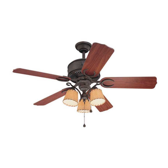
ITEM #0243307
AUSTIN CEILING FAN
MODEL #E-AM54AI5LKL
Español p. 19
E192641
Publicidad
Capítulos
Tabla de contenido

Manuales relacionados para Harbor Breeze E-AM54AI5LKL


Resumen de contenidos para Harbor Breeze E-AM54AI5LKL
- Página 1 ITEM #0243307 AUSTIN CEILING FAN MODEL #E-AM54AI5LKL Harbor Breeze® is a registered trademark Español p. 19 of LF, LLC. All Rights Reserved. Federal regulations require ceiling fans with light kits manufactured or imported after January 1, 2009, to limit total wattage consumed by the light kit to 190W. Therefore, this fan is equipped with a wattage limiting device.
-
Página 2: Tabla De Contenido
TABLE OF CONTENTS Safety Information ………………………………………………………...……..…....2 - 3 Package Contents ……………………………………………………..……..…..…....4 Hardware Contents ........................5 Preparation ..….…………………..……………………….…………….……………....5 Initial Installation ..……………………...…………………………………………..6 - 7 Fan Mounting ..…………………………………………………........7 - 8 Wiring ....……………………..........………....9 - 10 Final Installation …………….……………………….…………….……....…....11 - 14 Operation Instructions .......…………………………........14 - 15 Care and Maintenance ……………………………………………………………..……………..15 Troubleshooting ..………...………………………….……………..………......16 - 17... -
Página 3: Safety Information
SAFETY INFORMATION WARNINGS To reduce the risk of fire, electrical shock, or personal injury, mount fan to outlet box marked "ACCEPTABLE FOR FAN SUPPORT" and use mounting screws provided with the outlet box. Most outlet boxes commonly used for the support of lighting fixtures are not acceptable for fan support and may need to be replaced. -
Página 4: Package Contents
PACKAGE CONTENTS PART DESCRIPTION QUANTITY PART DESCRIPTION QUANTITY Motor Screw Downrod (preassembled) Canopy 5.4M/M Lock Washer Mounting Bracket (preassembled) Yoke Cover Canopy Mounting Screw Motor Housing (preassembled) Switch Housing Plate Pin (preassembled) Light Kit Fitter Clip (preassembled) Switch Housing Socket Ring Shade (preassembled) Blade Plate... -
Página 5: Hardware Contents
HARDWARE CONTENTS (shown actual size) Blade Fiber Screw Blade Washer E3 Wire Qty. 15 Connector Qty. 15 Qty. 4 PREPARATION Before beginning assembly and installation of product, make sure all parts are present. Compare parts with package contents list and hardware contents above. If any part is missing or damaged, do not attempt to assemble the product. -
Página 6: Initial Installation
INITIAL INSTALLATION Turn off circuit breakers and wall switch to the fan supply line leads. (Fig. 1) DANGER: Failure to disconnect power supply prior to installation may result in serious injury or death. Determine mounting method to use. (Fig. 2) A. -
Página 7: Fan Mounting
INITIAL INSTALLATION 5. Remove motor screws (P) and 5.4M/M lock washers (Q) from underside of motor and save for blade arm (K) attachment later on. [If there are plastic motor blocks installed with the motor screws (P) and 5.4M/M lock washers (Q), discard the plastic motor blocks.] (Fig. - Página 8 FAN MOUNTING Depending on the length of downrod (A) you use, you may need to cut the lead wires back to simplify the wiring. If you decide to cut back the lead wires, it is suggested that you do so in the following manner: Ball Take the lead wires and make sure that you have...
-
Página 9: Wiring
WIRING WARNING: To reduce the risk of fire, electrical shock, or personal injury, wire connectors provided with this fan are designed to accept only one 12 gauge house wire and two lead wires from the fan. If your house wire is larger than 12 gauge or there is more than one house wire to connect to the two fan lead wires, consult an electrician for the proper size wire connectors to use. - Página 10 WIRING FAN AND LIGHT CONTROLLED BY TWO WALL 1C. FAN AND LIGHT CONTROLLED BY TWO SWITCHES WALL SWITCHES: If you intend to control the fan BLACK (WALL SWITCH) and light with separate wall switches, connect BLACK (WALL SWITCH FOR LIGHT) BLACK wire from fan to BLACK wire from the 120 V Power FROM...
-
Página 11: Final Installation
FINAL INSTALLATION Locate two canopy mounting screws (R) on underside of mounting bracket (C) and remove canopy mounting screw (R) closest to the open end of of the mounting bracket (C). Partially loosen the other canopy mounting screw (R). Lift canopy (B) to mounting bracket (C). Place rounded part of slotted hole in canopy (B) over loosened canopy mounting screw (R) in mounting bracket (C) and push up. - Página 12 FINAL INSTALLATION Remove one screw from fitter plate (on underside of motor) and loosen the other two screws. Align slotted holes in switch housing plate (F) with loosened screws in fitter plate. Twist switch housing plate (F) to lock and re-install screw that was previously removed.
- Página 13 FINAL INSTALLATION Remove three screws from switch housing plate (F). Connect female plug from switch housing (H) to male plug from motor housing (E), matching up the colors on the male plug with the colors on the female plug for correct fit. Align holes in switch housing (H) with holes in switch housing plate (F).
-
Página 14: Operation Instructions
FINAL INSTALLATION The pull chain extensions (M) supplied in one of the hardware packs or custom pull chain extensions (sold separately) may be attached to fan and/or light pull chains. (Fig. 11) NOTE: This fan is remote control adaptable (remote control sold separately). OPERATION INSTRUCTIONS The pull chain on the switch housing (H) has four positions to control fan speed. -
Página 15: Care And Maintenance
OPERATION INSTRUCTIONS Use the fan reverse switch, located on the switch housing, to optimize your fan for seasonal performance. (Fig. 3) A ceiling fan will allow you to raise your thermostat setting in summer and lower Reverse Switch your thermostat setting in winter without feeling a difference in your comfort. -
Página 16: Troubleshooting
TROUBLESHOOTING If you have any questions regarding the product please call customer service at 1-800-527-1292, 8:30 a.m. - 5 p.m., CST, Monday - Friday. Warning: Before beginning work, shut off the power supply to avoid electrical shock. PROBLEM POSSIBLE CAUSE CORRECTIVE ACTION Fan does not move. -
Página 17: Warranty
TROUBLESHOOTING PROBLEM POSSIBLE CAUSE CORRECTIVE ACTION 4. Wires in switch housing (H) are 4. Check that male and female not connected properly. plugs and molex connections in switch housing (H) are connected properly according to instructions on page 12 and 13. 5. -
Página 18: Replacement Parts List
REPLACEMENT PARTS LIST For replacement parts, call our customer service department at 1-800-527-1292, 8:30 a.m. - 5:00 p.m., CST, Monday - Friday. When ordering parts, please have the Model # or Item # of the fan available, which can be found on page 1. PART DESCRIPTION Downrod... -
Página 19: Ventilador De Techo Austin
ARTICULO #0243307 VENTILADOR DE TECHO AUSTIN MODELO #E-AM54AI5LKL Harbor Breeze® es marca registrada de LF, LLC. Reservados todos los derechos. El reglamento federal requiere que un ventilador de techo con juego de luz fabricado o importado después del 1 de enero del 2009 limite el vatiaje total que consume el juego de luz a 190W. -
Página 20: Indice De Materias
INDICE DE MATERIAS Información de seguridad …………………………………......……...……..20 - 21 Contenido del paquete …………………………………………………………………..……..22 Contenido de artículos de ferretería ..................23 Preparación ....….…………………..……………………….…………….…..…..23 Instalación inicial .....…………………………………………………………..24 - 25 Montaje del ventilador ....................25 - 26 Conexión de los cables ………………………………………..…………....27 - 28 Instalación final ….…………….…….………………….……...…….……......29 - 32 Instrucciones de funcionamiento... - Página 21 INFORMACION DE SEGURIDAD ADVERTENCIAS Para reducir el riesgo de incendio, choque eléctrico o daño corporal, sujete el ventilador a una caja de salida marcada "Aceptable para sostener ventilador" ("ACCEPTABLE FOR FAN SUPPORT" en inglés) y use los tornillos de montaje proporcionados con la caja de salida.
-
Página 22: Contenido Del Paquete
CONTENIDO DEL PAQUETE PIEZA DESCRIPCION CANTIDAD PIEZA DESCRIPCION CANTIDAD Tornillo del motor Vástago (preensamblado) Cubierta Arandela de seguridad Soporte de montaje 5,4M/M (preensamblada) Cubierta del yugo Tornillo para montaje de la Bastidor del motor cubierta (preensamblado) Placa de la caja del Clavija (preensamblada) interruptor Sujetador (preensamblado) -
Página 23: Contenido De Artículos De Ferretería
CONTENIDO DE ARTICULOS DE FERRETERIA (se muestra en tamaño natural) Tornillo Arandela para la de fibra paleta para la Conector paleta para cable Ctd. 15 Ctd. 15 Ctd. 4 PREPARACION Antes de empezar con el ensamblaje e instalación del producto, asegúrese de tener todas las piezas. -
Página 24: Instalación Inicial
INSTALACION INICIAL Apague todos los disyuntores del circuito y el interruptor de pared a la línea de suministro de electricidad del ventilador. (Fig. 1) PELIGRO: El no desconectar el suministro de electricidad antes de la instalación puede resultar en daños graves o la muerte. Determine el método de montaje. -
Página 25: Montaje Del Ventilador
INSTALACION INICIAL Saque los tornillos del motor (P) y las arandelas de seguridad 5,4M/M (Q) del lado inferior del motor y guárdelos para sujetar los brazos para las paletas (K) más adelante. [Si hay también soportes de plástico del motor instalados con los tornillos del motor (P) y las arandelas de seguridad 5,4M/M (Q), deseche los soportes de plástico.] (Fig. - Página 26 MONTAJE DEL VENTILADOR Dependiendo del largo del vástago (A) que use, es posible que tenga que cortar los cables principales para facilitar la conexión de cables. Si usted elige cortar los cables principales, se le sugiere hacerlo de la manera que sigue: bola Tome los cables principales y asegúrese de que los haya jalado completamente por la parte superior del...
-
Página 27: Conexión De Los Cables
CONEXION DE LOS CABLES ADVERTENCIA: Para reducir el riesgo de incendio, choque eléctrico o daño corporal, los conectores para cable provistos con este ventilador son diseñados para aceptar sólo un cable de calibre 12 de la casa y dos cables principales del ventilador. -
Página 28: Ventilador Y Luz Controlados Por Dos Interruptores De Pared
CONEXION DE LOS CABLES 1C. VENTILADOR Y LUZ CONTROLADOS POR VENTILADOR Y LUZ CONTROLADOS POR DOS INTERRUPTORES DE PARED DOS INTERRUPTORES DE PARED: Si usted piensa controlar la luz y el ventilador con interruptores NEGRO (INTERRUPTOR DE PARED) distintos, conecte el cable NEGRO del ventilador al 120 V cables (INTERRUPTOR DE PARED para la LUZ) de corriente... -
Página 29: Instalación Final
INSTALACION FINAL Localice los dos tornillos para montaje de la cubierta (R) en la parte inferior del soporte de montaje (C) y quite el tornillo para montaje de la cubierta (R) que está localizado más cerca del extremo abierto del soporte de montaje (C). - Página 30 INSTALACION FINAL Quite un tornillo de la placa de conexión (en la parte inferior del motor) y afloje los otros dos tornillos. Alinee los agujeros con ranura en la placa de la caja del interruptor (F) con los tornillos aflojados en la placa de conexión.
- Página 31 INSTALACION FINAL Quite los tres tornillos de la placa de la caja del interruptor (F). Conecte el enchufe hembra de la caja del interruptor (H) al enchufe macho del bastidor del motor (E) haciendo coincidir los colores en el enchufe macho con los del enchufe hembra para que se conecten correctamente.
-
Página 32: Instrucciones De Funcionamiento
INSTALACION FINAL Se pueden fijar las extensiones para las cadenas de encendido (M) provistas en uno de los paquetes de artículos de ferretería a las cadenas de encendido para el ventilador y/o la luz o usar unas extensiones para cadenas de encendido hechas a medida (a la venta por separado). -
Página 33: Cuidado Y Mantenimiento
INSTRUCCIONES DE FUNCIONAMIENTO Use el interruptor de reversa, localizado en la caja del interruptor, para optimizar el uso del ventilador interruptor durante las estaciones del año. (Fig. 3) Un de reversa ventilador de techo le permitirá subir el termostato en verano y bajarlo en invierno sin notar una diferencia en su comodidad. -
Página 34: Localización De Fallas
LOCALIZACION DE FALLAS Si tiene alguna pregunta acerca del producto, por favor llame al servicio al cliente al 1-800-527-1292, de 8:30 a.m. a 5:00 p.m., hora central, de lunes a viernes. ADVERTENCIA: Antes de proseguir, desconecte la electricidad, quitando los fusibles o cortando el suministrode energía de los circuitos para evitar un choque eléctrico. - Página 35 LOCALIZACION DE FALLAS PROBLEMA CAUSA POSIBLE ACCION CORRECTIVA El ventilador funciona 1. No se instalaron bien la(s) 1. Instale la(s) bombilla(s) de pero las luces no bombilla(s). nuevo. (si aplica). 2. No se conectaron correctamente 2. Verifique que se conectaron bien los cables en la cubierta (B).
-
Página 36: Garantía
GARANTIA GARANTIA LIMITADA DE POR VIDA: Litex Industries garantiza que este ventilador está libre de defectos de mano de obra y de materiales desde la fecha de salida de la fábrica por el tiempo de por vida limitada a partir de la fecha de compra. Esta garantía sólo se aplica al comprador original. Litex Industries se compromete a corregir cualquier defecto libre de cargo o, si lo considera necesario, a reemplazar el ventilador por un modelo equiparable o superior. -
Página 37: Lista De Piezas De Repuestos
LISTA DE PIEZAS DE REPUESTOS Para piezas de repuesto, llame a nuestro departamento de servicio al cliente al 1-800-527-1292, de 8:30 a.m. a 5:00 p.m., hora central, de lunes a viernes. Al pedir piezas, por favor tenga listo el No. de modelo o No.