Tabla de contenido
Publicidad
Idiomas disponibles
Idiomas disponibles
Enlaces rápidos
Compact Installation
VEHICULAR SWING GATE OPERATORS
•
•
•
•
LiftMaster
845 Larch Avenue
Elmhurst, IL 60126-1196
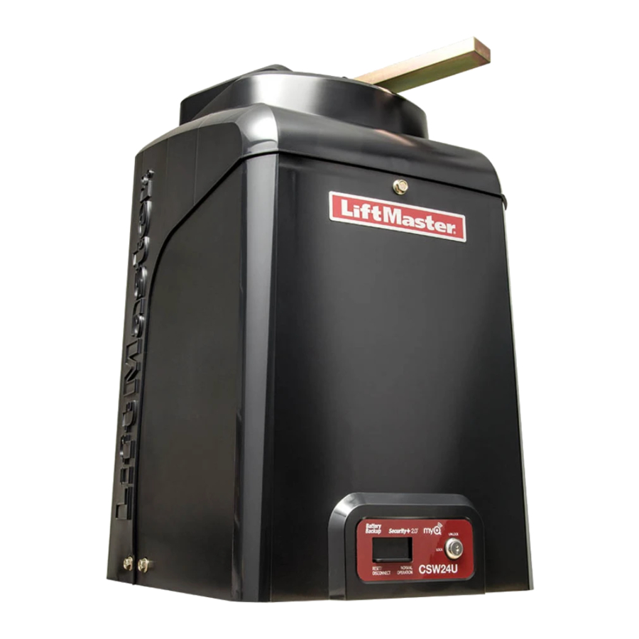
MODELS CSW24U, RSW12U, AND CSW200U
THIS PRODUCT IS TO BE INSTALLED AND SERVICED BY A TRAINED GATE
SYSTEMS TECHNICIAN ONLY.
These instructions are for applications where the gate operator arm may hit an
obstruction during movement. If the distance between the open gate and an
obstruction is between 20 to 32 inches, a compact installation is necessary.
Refer to the installation manual for complete information regarding warnings,
installation, testing, and programming. Each application is unique and it is the
responsibility of the purchaser, installer and end user to ensure that the total gate
system is installed and operated properly.
The images in these instructions are generic. Your operator may look different.
FOR
Publicidad
Tabla de contenido

Manuales relacionados para LiftMaster CSW24U


Resumen de contenidos para LiftMaster CSW24U
- Página 1 Compact Installation VEHICULAR SWING GATE OPERATORS MODELS CSW24U, RSW12U, AND CSW200U • THIS PRODUCT IS TO BE INSTALLED AND SERVICED BY A TRAINED GATE SYSTEMS TECHNICIAN ONLY. • These instructions are for applications where the gate operator arm may hit an obstruction during movement.
-
Página 2: Install The Concrete Pad And Operator
STEP 1 Install the concrete pad and operator Check the national and local building codes before installation. DO NOT run the operator until instructed. Refer to the illustration to determine the location for the concrete pad, conduit, and operator. 6" Above Ground TOP VIEW OF OPERATOR AND GATE There should only be a maximum of 4"... -
Página 3: Shorten The Operator Arm
STEP 2 Shorten the Operator Arm LONG ARM SECTION (cut) (cut) 10" 22" 4" SHORT ARM SECTION (cut) 4" 20" Take the operator arm apart and remove the inner sleeves from the outer tubing. Cut the outer tubing of the operator arm sections to the lengths shown. -
Página 4: Position The Gate Bracket
Use the set screws on the arm to temporarily hold the arm in place while determining the correct measurements. 33" 27-1/2" Make sure the operator arm is level and tack weld the gate bracket in this position. Continue to Installation Step 5 in the manual. PAS001 © 2015, LiftMaster – All Rights Reserved... - Página 5 Installation compacte POUR ACTIONNEURS DE PORTAIL PIVOTANT POUR VÉHICULES MODÉLES CSW24U, RSW12U, ET CSW200U • CE PRODUIT DOIT ÊTRE EXCLUSIVEMENT INSTALLÉ ET ENTRETENU PAR UN PERSONNEL DÛMENT FORMÉ SUR LES SYSTÈMES DE PORTAIL. • Ces instructions concernent les applications dans lesquelles le bras de l’actionneur de barrière en mouvement peut heurter un obstacle.
- Página 6 ÉTAPE 1 Installer la dalle de béton et l’actionneur Vérifier les codes de construction nationaux et locaux avant l’installation. NE PAS faire fonctionner l’actionneur avant que cela soit expressément indiqué. Consulter l’illustration pour déterminer l’emplacement de la plaque de béton, de la conduite et de l’actionneur. 6 po (15,2 cm) au-dessus du sol VUE DE HAUT DE L’ACTIONNEUR ET DE LA BARRIÈRE...
- Página 7 ÉTAPE 2 Raccourcissez le bras de l’actionneur PARTIE LONGUE DU BRAS (coupez) (coupez) 10 po. 22 po. PARTIE COURTE DU BRAS (coupez) 20 po. Démontez le bras de l’actionneur et retirez les gaines internes à l’intérieur des tubes. Coupez les tubes externes du bras de l’actionneur aux longueurs indiquées.
- Página 8 33 po. 27-1/2 po. Assurez-vous que le bras de l’actionneur est droit et clouez le support de la barrière dans cette position. Continuer à l’étape 5 de l’installation dans le manuel. PAS001 © 2015, LiftMaster –Tous droits réservés...
-
Página 9: Instalación Compacta
Instalación Compacta PARA OPERADOR DE PORTÓN GIRATORIO PARA VEHÍCULOS MODELOS CSW24U, RSW12U, Y CSW200U • ESTE PRODUCTO DEBE SER INSTALADO O REPARADO SOLAMENTE POR UN TÉCNICO PROFESIONAL EN OPERADORES DE PORTONES. • Estas instrucciones son para el caso de que el brazo encuentre una obstrucción durante el movimiento. -
Página 10: Construir La Plataforma De Concreto E Instalar El Operador
PASO 1 Construir la plataforma de concreto e instalar el operador Verifique los códigos nacionales y locales antes de la instalación. NO active el operador hasta que se le indique. Consultar la ilustración para determinar la ubicación de la base de concreto, el conducto y el operador. 6 pulg. -
Página 11: Acortar El Brazo Del Operador
PASO 2 Acortar el brazo del operador SECCIÓN LARGA DEL BRAZO (cortar) (cortar) 10 pulg. 22 pulg. pulg. SECCIÓN CORTA DEL BRAZO (cortar) 20 pulg. Desarmar el brazo y quitar los manguitos internos de los pulg. tubos. Cortar el tubo externo del brazo a la medida indicada. Volver a armar el brazo y regular su longitud a la medida indicada. -
Página 12: Colocar En Posición La Ménsula Del Portón
33 pulg. 27-1/2 pulg. Verificar que el brazo esté nivelado y fijar la ménsula en esta posición con puntos de soldadura. Continuar con el paso 5 de instalación del manual. PAS001 © 2015, LiftMaster – Reservados todos los derechos de ley...