Tabla de contenido
Publicidad
Idiomas disponibles
Idiomas disponibles
Enlaces rápidos
Publicidad
Tabla de contenido

Manuales relacionados para Solter Core 140i


Resumen de contenidos para Solter Core 140i
- Página 1 MANUAL DE INSTRUCCIONES INSTRUCCIONES PARA EL USO Y EL MANTENIMIENTO. LEA ESTE MANUAL ANTES DE PONER EN MARCHA EL EQUIPO. INSTRUCTION MANUAL INSTRUCTIONS FOR THE USE AND MAINTENANCE. READ THIS MANUAL BEFORE STARTING THE EQUIPMENT. MI03160-05 SOLTER SOLDADURA S.L.
-
Página 2: Tabla De Contenido
WELDING SCHEME WITH COATED ELECTRODE ...................... 13 MAINTENANCE INSTRUCTIONS ..........................14 TROUBLESHOOTING ..............................14 ESQUEMA ELÉCTRICO / WIRING DIAGRAM ......................15 CERTIFICADO DE GARANTÍA / CERTIFICATE OF GUARANTEE ................16 DECLARACIÓN DE CONFORMIDAD / DECLARATION OF CONFORMITY ..............16 SOLTER SOLDADURA S.L. -
Página 3: Español Introducción
Rogamos se abstenga de efectuar cualquier manipulación en el aparato (sólo personal formado técnicamente por Solter Soldadura S.L. puede realizarlo). Solter Soldadura S.L. declina toda responsabilidad por prácticas negligentes en la utilización y/o manipulación. Éste equipo de soldadura no debe utilizarse para descongelar tuberías. -
Página 4: Descripciones Generales
Número de fases de alimentación conectadas 50/60 Hz Frecuencia de red. IP XX Grado de protección exterior de la máquina. CARACTERÍSTICAS TÉCNICAS Core 140i Core 150i Core 160i Core 200i Voltaje de entrada (U1) 230V (220 ~ 240) 230V (220 ~ 240) -
Página 5: Descripción De Los Elementos Del Equipo
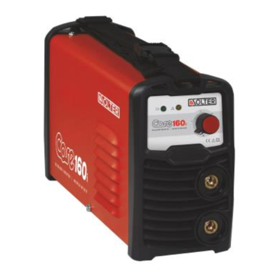
DESCRIPCIÓN DE LOS ELEMENTOS DEL EQUIPO MODELO CORE 140I 1 - Salida de potencia activa 2 - Anomalía 3 - Potenciómetro de regulación 4 - Conector polo negativo (10-25) 5 - Conector polo positivo (10-25) MODELO CORE 150I 1 - Salida de potencia activa 2 - Anomalía... -
Página 6: Transporte E Instalación Del Equipo De Soldadura
óxido. La tabla siguiente muestra la sección de cable recomendada por Solter Soldadura según amperaje y ciclo de trabajo para longitudes inferiores a 25m. Estos datos son como referencia y pueden NO adaptarse a todas las aplicaciones. -
Página 7: Elección Del Electrodo
5 - Situar el potenciómetro de regulación en una posición adecuada para iniciar la soldadura. INSTRUCCIONES DE MANTENIMIENTO Se recomienda una supervisión periódica del equipo. Antes de realizar cualquier operación de mantenimiento, desconecte el equipo de la red de alimentación. Reduzca los plazos de mantenimiento aconsejados ante condiciones de uso severas. SOLTER SOLDADURA S.L. -
Página 8: Averías
Polaridad invertida. Poros en la soldadura. Electrodo húmedo. Pieza muy fría al soldarla. Salpicaduras. Exceso de intensidad de soldadura. Arco inestable. Pieza con óxido, o mal preparada para soldar, revisar el contacto de la pinza de masa. SOLTER SOLDADURA S.L. -
Página 9: English Introduction
Internal manipulation of the equipment involves the risk of electric shocks and also voids warranty. We request you not to carry out any manipulation of the equipment (only technically trained personnel by Solter Soldadura S.L. can do this). Solter Soldadura S.L. denies all responsibility for negligent practices in the use or manipulation of this machine. This manual must be kept with the equipment purchased. -
Página 10: General Descriptions
X ph Number of phases to be connected 50/60 Hz Frequency. IP XX IP protection class. TECHNICAL SPECIFICATIONS Core 140i Core 150i Core 160i Core 200i Input voltage (U1) 230V (220 ~ 240) 230V (220 ~ 240) 230V (220 ~ 240) -
Página 11: Description Of The Equipment Parts
The machine is designed to be used outdoors. However, it should be protected from rainfall while it’s in use. DESCRIPTION OF THE EQUIPMENT PARTS CORE 140I MODEL 1 - Power output activated 2 - Alarm indicator 3 - Regulation potentiometer... -
Página 12: Operating Cycle And Overheating
Make sure the surface is completely clean and free of paint and rust. The following table shows the cable section, recommended by Solter Soldadura, according to amperage and operating cycle for lengths of less than 25m. These data are for reference and may NOT suit all applications. If the cable overheats, use a larger cable section. -
Página 13: The Choice Of Electrode
2 - Connect the electrode holder to the positive terminal (+). 3 - Insert the electrode into the electrode-holder clamp. 4 - Connect the machine to the electrical supply. 5 – Adjust the potentiometer in a suitable position in order to begin welding SOLTER SOLDADURA S.L. -
Página 14: Maintenance Instructions
Welding too fast. Reverse polarity. Pores in the weld. Moist electrode. Parts are cold on welding. Spattering. Excess welding current. Unstable arc. Rusty piece or poorly prepared piece for welding, check the contact for the earth terminal. SOLTER SOLDADURA S.L. -
Página 15: Esquema Eléctrico / Wiring Diagram
ESQUEMA ELÉCTRICO / WIRING DIAGRAM SOLTER SOLDADURA S.L. -
Página 16: Certificado De Garantía / Certificate Of Guarantee
CERTIFICADO DE GARANTÍA / CERTIFICATE OF GUARANTEE Los productos SOLTER están diseñados para aplicaciones industriales y profesionales. Tanto la construcción como las estrictas pruebas y controles de calidad garantizan productos de 1 a 3 años dependiendo del tipo de producto y del territorio donde se adquiere el producto.