
Manuales relacionados para Citizen CT-S651 Type II


Resumen de contenidos para Citizen CT-S651 Type II
- Página 1 LINE THERMAL PRINTER MODEL CT-S651 Type II User’s Manual Mode d’emploi Benutzerhandbuch Manuale dell’utente Manual de Usuario...
- Página 2 WEEE MARK If you want to dispose of this product, do not mix it with general household waste. There is a separate collection systems for used electronics products in accordance with legislation under the WEEE Directive and is effective only within European Union. Wenn Sie dieses Produkt entsorgen wollen, dann tun Sie dies bitte nicht zusammen mit dem Haushaltsmüll.
- Página 3 Declaration of Conformity This printer conforms to the following Standards: The Low Voltage Directive 2006/95/EC, the EMC Directive 2004/108/EC, the RoHS Directive 2011/65/EU, and the WEEE Directive 2002/96/EC. LVD : EN60950-1 EMC: EN55022 Class A EN61000-3-2 EN61000-3-3 EN55024 This declaration applies only to the 230-V model. IMPORTANT: This equipment generates, uses, and can radiate radio frequency energy and if not installed and used in accordance with the instruction manual, may cause interference to radio communications.
- Página 4 ENGLISH...
- Página 5 If you find omissions, errors, or have questions, please contact your Citizen Systems dealer. If you find any pages missing or out of order, contact your Citizen Systems dealer for a replacement. "Made for iPod," "Made for iPhone," and "Made for iPad" mean that an electronic...
- Página 6 SAFETY PRECAUTIONS ...WHICH SHOULD BE STRICTLY OBSERVED Before using this product for the first time, carefully read these SAFETY PRECAUTIONS. Improper handling may result in accidents (fire, electric shock or injury). In order to prevent injury to operators, third parties, or damage to property, special warning symbols are used in the User’s Manual to indicate important items to be strictly observed.
- Página 7 • Dropping a metallic foreign object into the printer, may cause printer failure, fire, or electric shock. Should it occur, immediately turn the printer off, unplug it from the supply outlet, and call your local Citizen Systems dealer. Do not handle the printer in the following ways: ...
- Página 8 CAUTION Do not use the printer under the following conditions. Avoid locations subject to vibration or instability. Avoid locations where the printer is not level. • The printer may fall and cause an injury. • The quality of printing may deteriorate. ...
- Página 9 • Neglecting these cautions may cause wires or insulation to break, which could result in electric leakage, electric shock, or printer failure. If the power cord sustains damage, contact your Citizen Systems dealer. Do not leave things around the electric outlet.
- Página 10 CAUTION Caution label is attached in the position shown in the following figure. Carefully read the handling precautions before using the printer. THIS LABEL INDICATES THE RISK OF BURNS DUE TO THE HIGH TEMPERATURE OF THE PRINT HEAD AND A RISK OF BEING CUT BY THE MANUAL AND AUTO CUTTERS WHILE THE PAPER COVER IS OPEN.
- Página 11 Do not touch any of the moving parts (e.g., paper cutter, gears, active electric parts) while the printer is working. In case of trouble do not attempt to repair the printer. Ask Citizen Systems service for repair. Be careful that the covers do not pinch your hands or fingers.
-
Página 12: Tabla De Contenido
THE TABLE OF CONTENTS 1. GENERAL OUTLINE ..............9 1.1 Features................... 9 1.2 Unpacking..................10 1.3 Model Classification ..............10 1.4 Basic Specifications............... 11 2. EXPLANATION OF PRINTER PARTS ........12 2.1 Printer Appearance ................ 12 2.2 Inside the Paper Cover ..............15 2.3 Other Built-in Functions.............. -
Página 13: General Outline
1. GENERAL OUTLINE The CT-S651II line thermal printer series is designed for use with a broad array of terminal equipment including data, POS, and kitchen terminals. These printers have extensive features so they can be used in a wide range of applications. -
Página 14: Unpacking
A: Asia/Oceania WF: WiFi W5: WiFi(5.0GHz) HET: Ethernet (USB host function) Certain combinations may not be available. Check with Citizen beforehand. Note: *: AC power cord, serial I/F screw, firmware and other specifications vary according to markets. — 10 —... -
Página 15: Basic Specifications
1.4 Basic Specifications Item Specifications Model CT-S651II Print method Line thermal dot print method Print width 80 mm/640 dots, 72 mm/576 dots, 64 mm/512 dots, 54.5 mm/436 dots, 54 mm/432 dots, 52.5 mm/420 dots, 48 mm/384 dots, 45 mm/360 dots, 48.75 mm/390 dots, 68.25 mm/546 dots 8 ×... -
Página 16: Explanation Of Printer Parts
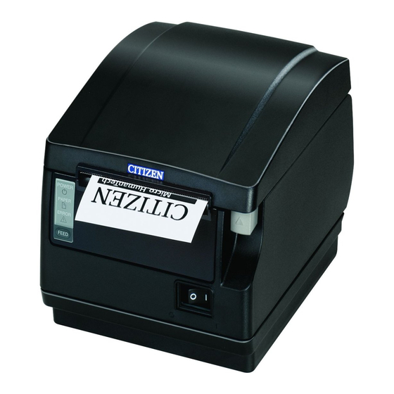
*4: The 36AD2/37AD5 is the AC adapter packaged as an accessory with the CT-S651IIA. The 36AD3/37AD3 is the AC adapter built in to the CT-S651IIS. *5: Compliant if the Citizen Systems AC adapter (36AD2/3, 37AD3/5) is used. 2. EXPLANATION OF PRINTER PARTS 2.1 Printer Appearance... - Página 17 Operation panel POWER LED (green) PAPER LED (orange) ERROR LED (red) FEED button POWER LED (green) Lights when the power is on, turns off when the power is off. Flashes when data is incoming or a memory error has occurred. ...
- Página 18 Rear connectors Cash drawer Interface connector Power connector (AC adapter type) kick-out (serial, parallel, USB, etc.) connector AC inlet (built-in power supply type) Interface connector (serial, parallel, USB, etc.) Connects to the interface cable. The serial interface board is equipped with a DIP switch. ...
-
Página 19: Inside The Paper Cover
2.2 Inside the Paper Cover Print head (thermal) Manual cutter Button to change paper near-end sensor Paper near-end sensor (PNE sensor) Auto cutter Paper-end sensor (PE sensor) Platen Platen Feeds the paper. Do not remove the platen except to do maintenance. ... -
Página 20: Other Built-In Functions
Paper end sensor (PE sensor) Detects when there is no paper. Printing stops when this sensor detects there is no paper. 2.3 Other Built-in Functions Buzzer Buzzes when errors occur or when operations or command operations are performed. Refer to 4.6 Error Messages ... - Página 21 Auto side shift (MSW8-6) This function dissipates heat load during frequent heat generation by a vertical ruled line or other specific head heating element. If no data is received within 15 seconds after each cut or print, the print position is automatically slid N* dots to the right.
-
Página 22: Setup
3. SETUP 3.1 Connecting the AC Power Cord Turn off the power. For the built-in power type printer, connect the AC power cord to the AC inlet, and insert the plug into an electric outlet. For the AC adapter type printer, connect the cable connector of the AC adapter to the power connector. -
Página 23: Serial Interface Board
3.2 Serial Interface Board Data can be exchanged by serial communication. Connecting the Interface Cable Turn off the power. Orient the cable correctly and insert it into the connector. Insert the other connector firmly into the interface port of the host computer. CAUTION ... -
Página 24: Usb Interface Board
3.3 USB Interface Board Data can be exchanged by USB communication. Specifications Standard USB 2.0 specification-compliant Communication speed Supports 12 Mbps (Full-Speed) transfer Connecting the Interface Cable Turn off the power. Orient the cable correctly and insert it into the connector. Insert the other connector firmly into the interface port of the host computer. -
Página 25: Bluetooth Interface Board
3.4 Bluetooth Interface Board Bluetooth status LED Status LED Switch The LED on the Bluetooth interface board on the rear of the printer indicates the status below. Status Description LED Status Detection Standing by for standby detection and (Discoverable) connection Connection Standing by for standby... - Página 26 B: Configuring pairing settings Normally, selecting the printer during device detection will transition directly to pairing settings. CAUTION Some host PC configurations and models may not transition directly to pairing settings after the printer is selected during device detection. The operation required to configure pairing settings depends on whether SSP (secure simple pairing) is enabled on the host PC.
-
Página 27: Ethernet (Lan)/Wireless Lan Interface Board
3.5 Ethernet (LAN)/Wireless LAN Interface Board This section provides an overview of the interface board. For details on this board, including explanations about the USB host function and XML peripheral device support,refer to the separate manual. Connecting the Interface Cable Turn off the power. - Página 28 Panel button operation Board operations are performed using the panel button on the rear of the LAN board. Panel button 10/100BASE Panel button Panel button Ethernet Wireless LAN Ethernet USB host model Enabling LAN connection Turn on the printer. Operation of this board will start about 20 seconds later. ...
- Página 29 LED Functions The tables below explain how to interpret LED indications. 10/100BASE 10/100BASE Ethernet Wireless LAN Ethernet USB host model 1. Wired LAN transmission speed Transmission speed LED (green) 100 Mbps 10 Mbps/Not connected Unlit 2. Wired LAN connection/transmission status Connection status LED (yellow) Connected...
- Página 30 Web Manager The interface board has a Web Manager function that can be used to connect to the board with a web browser and change board settings. Starting up Web Manager Start up a web browser. In the address field, input the board's IP address and then press [Enter]. HOME Screen This is the Web manager home screen.
- Página 31 CONFIG Screen This will display the Login dialog box shown below. Log in as an administrator and then configure interface board settings. User Name Input a board administrator user name. (Initial setting: admin) Password Input the administrator user password. (Initial setting: admin) ...
-
Página 32: The Previous Model Ethernet (Lan) Interface Board
3.6 The previous model Ethernet (LAN) Interface Board This section provides an overview of the Ethernet (LAN) interface board. For details about this board, refer to the separate manual. Panel button operation Board operations are performed using the panel button on the Ethernet board. You can use the button to print setup information and to return the board to its factory settings. - Página 33 LED Functions The tables below explain how to interpret LED indications. 10/100BASE 1. Network transmission speed Transmission speed LED (green) 100Mbps 10Mbps/Not connected Unlit 2. Network status Status LED (yellow) Connected Not connected Unlit Data transmission in Flashing progress 3. Board status Status LED (green) LED (red)
- Página 34 Changing network settings You can use a web browser to access a special settings page to check and change board settings. Accessing the special settings page Use a web browser to access the URL of the special settings page. Specify the IP address assigned to the printer as the URL.
-
Página 35: Connecting Other Interface Cables
Powered USB interface. Failure to do so may damage the host PC. For information about installing a Powered USB interface, contact your Citizen Systems dealer. Check the orientation of the Powered USB cable connector before connecting it. Insert it straight in so that the pins do not bend. -
Página 36: Connecting The Cash Drawer
3.8 Connecting the Cash Drawer Turn off the power. Confirm the orientation of the cash drawer kick-out cable connector and connect it to the cash drawer kick-out connector at the back of the printer. Remove the screw for the ground wire. Screw the cash drawer’s ground wire to the body of the printer. - Página 37 (1) Connector pin configuration Signal Function Frame ground Connector used: TM5RJ3-66 (Hirose) or DRAWER1 Cash drawer 1 drive signal equivalent DRSW Cash drawer switch input Applicable connector: Cash drawer drive power supply TM3P-66P (Hirose) or equivalent DRAWER2 Cash drawer 2 drive signal Signal ground (common ground on circuits) (2) Electric characteristics...
-
Página 38: Precautions For Installing The Printer
3.9 Precautions for Installing the Printer This printer can only be positioned horizontally. It cannot be positioned vertically or on a wall. Vertical position Horizontal position CAUTION Do not use the printer under the following conditions. Locations subject to vibration or instability. ... -
Página 39: Partition For Paper Roll
3.10 Partition for Paper Roll Set the partition to the width of the paper roll you are loading. The partition is set at the factory to the position shown below. For 3-inch type: 80-mm wide paper roll For 2-inch type: 58-mm wide paper roll, 60-mm wide paper roll (2-sheet partition installed.) Turn off the power. -
Página 40: Setting The Dip Switch On The Serial Interface Board
3.11 Setting the DIP Switch on the Serial Interface Board Turn off the printer and unplug the power cord from the electric outlet. Remove the mounting screws of the serial interface board. Remove the serial interface board from the printer. Set the DIP switch according to the following table. -
Página 41: Adjusting The Paper Near-End Sensor
3.12 Adjusting the Paper Near-end Sensor Change the settings of the paper near-end sensor to set the position at which the near-end of the paper is detected. Use a pointed object, such as a pen, to gently press the button to change the paper near-end sensor. -
Página 42: Loading Paper
3.13 Loading Paper Turn on the power. Press up on the cover open button to open the paper cover. Load the paper roll so that the printable side of the paper is facing up, as shown by arrow A. Pull a few cm of paper straight out in the direction of arrow B. Close the paper cover until you hear a click. -
Página 43: Attaching The Power Switch Cover
3.14 Attaching the Power Switch Cover Attach this cover to prevent the power switch from being used. Press the power switch cover onto the power switch compartment until it clicks. Power switch cover Put a screwdriver or other pointed object into the grooves on the power switch cover to remove it. -
Página 44: Attaching The Interface Cover
3.15 Attaching the Interface Cover Attach the interface cover to the back of the printer. The shape of the interface cover is different depending on the type of power source. Press the interface cover as shown in the diagram until you hear it click. CT-S651IIS 3.16 Removing the Interface Cover... -
Página 45: Installing A Driver
Install the driver required by your printer. For information about driver installation, functions, and operations, see the information provided on the CD-ROM for each driver. Visit the site below to download the latest driver versions and information. http://www.citizen-systems.co.jp/english/support/download/printer/driver/ 3.18 Precautions for Creating Applications and Practical Operations If printing is done immediately after the paper is partially cut and torn off, the top of the next print out may be distorted. -
Página 46: Maintenance And Troubleshooting
MAINTENANCE AND TROUBLESHOOTING 4.1 Periodic Cleaning A dirty print head or platen may reduce printing quality or cause malfunctions. We recommend cleaning the printer periodically (every 2 to 3 months) as shown below. Turn off the power. Press up on the cover open button to open the paper cover. Wait a few minutes until the print head cools. -
Página 47: Clearing A Cutter Lock (1)
4.2 Clearing a Cutter Lock (1) The ERROR LED flashes and the auto cutter blade remains extended because a foreign object or paper jam is obstructing it. If the ERROR LED is flashing, clear the locked cutter as shown below. Turn on the power. - Página 48 The print head is hot immediately after printing. Do not touch it. Do not touch the print head with bare hands or metal objects. If the above procedure does not retract the auto cutter, contact your Citizen Systems dealer. — 44 —...
-
Página 49: Self Test
4.4 Self test While paper is loaded, press and hold the FEED button while turning the power on. Hold the FEED button down for about one second and then release it to start self test. The printer prints its model name, version, DIP switch settings, memory switch settings, and a list of built-in fonts. -
Página 50: Hexadecimal Dump Printing
4.5 Hexadecimal Dump Printing Print received data in hexadecimal. If problems such as missing or duplicated data occur, this function allows you to check whether or not the printer is receiving data correctly. How to do hexadecimal dump printing Load paper. While the paper cover is open, press and hold the FEED button while turning the power on, and then close the paper cover. -
Página 51: Error Messages
4.6 Error Messages Paper-end The end of the roll of paper is detected at two stages, paper near-end and paper-end. When paper near-end is detected, the PAPER LED lights. Prepare a new paper roll. When paper end is detected, the PAPER LED and ERROR LED light. Load a new paper roll. - Página 52 The status display for various messages is shown below. POWER LED PAPER LED ERROR LED Status Buzzer (green) (orange) (red) Paper near-end Lights Lights — Paper-end Lights Lights Lights Paper cover open or front cover Lights — Lights open Paper cover open or front cover Lights —...
-
Página 53: Paper Jams
4.7 Paper Jams Take care to avoid obstruction of the paper outlet and paper jamming around the outlet during printing. If paper cannot get out of the printer, it can roll up on the platen inside the printer and cause an error. If the paper wraps around the platen, open the paper cover and carefully pull the paper out. -
Página 54: Other
5. OTHER 5.1 External Views and Dimensions (Unit: mm) Built-in power supply type AC adapter type — 50 —... -
Página 55: Printing Paper
5.2 Printing Paper Use the paper shown in the following table or paper of the same quality. Paper type Product name Recommended TF50KS-E2D, TF50KS-E or TF60KS-E from Nippon Paper thermal roll PD150R or PD160R from Ohji Paper paper P220AG, HP220A, HP220AB-1, F230AA, P220AB or PB670 (2-color paper) from Mitsubishi Paper (Unit: mm) Printable side... -
Página 56: Manual Setting Of Memory Switches
5.3 Manual Setting of Memory Switches Memory switches are used to set various printer settings. The memory switches can be set manually (set by hand on the printer) or by commands. This section explains how to perform manual settings. For information on how to set the memory switches using commands, please refer to the Command Reference. - Página 57 MSW3-7 MSW8-1 MSW6-2 Paper Character Manufacturer Model Full Col CBM1000 Print Character width space Print Mode Width Space CITIZEN CBM1000 58 mm — Auto Valid 432dots — linefeed 80 mm — Auto Valid 576dots — linefeed CT-S300 58 mm —...
- Página 58 Press the FEED button for at least two seconds. A setting for the memory switch is printed, through the cycle, each time the FEED button is pressed for at least two seconds. Press the FEED button for at least two seconds to cycle through the list until the function of the memory switch you want to change is printed.
- Página 59 The function of each memory switch is shown in the following table. (Shaded values are factory settings.) Switch no. Function MSW1-1 Power ON Info Valid Not Send MSW1-2 Buffer Size 4K bytes 45 bytes MSW1-3 Busy Condition Full/Err Full MSW1-4 Receive Error Print“?”...
- Página 60 Switch no. Function MSW6-1 Act. For Driver Invalid Valid MSW6-2 Character Space Invalid Valid MSW6-3 USB Power Save Invalid Valid MSW6-4 Reserved Fixed — MSW6-5 Reserved Fixed — MSW6-6 Reserved Fixed — MSW6-7 Reserved Fixed — MSW6-8 Reserved Fixed — Switch no.
- Página 61 Switch no. Function Initial setting Setting value MSW10-4 Old Command Invalid Invalid, CBM1, CBM2 MSW10-5 Buzzer Event Not by All Event/Error, Not by C.Open, Not by C.Open/PE C.Open MSW10-6 Buzzer Sound Tone 2 Tone 1, Tone 2, Tone 3, Tone 4 MSW13-1 Security/Target Low/All...
- Página 62 FRANÇAIS...
- Página 63 CITIZEN is a registered trademark of Citizen Watch Co., Ltd. Japan All other trademarks are the property of their respective owners. Citizen Systems use these trademarks in accordance with the license of relevant owners. Copyright ©2019 by CITIZEN SYSTEMS JAPAN CO., LTD.
- Página 64 PRÉCAUTIONS DE SÉCURITÉ ..QUI DEVRAIENT ÊTRE OBSERVÉES RIGOUREUSEMENT Veuillez lire attentivement ces PRÉCAUTIONS DE SÉCURITÉ avant d’utiliser l’appareil pour la première fois. La manipulation incorrecte peut avoir comme conséquence des accidents (incendie, décharge électrique ou blessures). Afin d’éviter des blessures aux opérateurs, tiers, ou des dommages à...
- Página 65 électrocution. Dans ce cas, mettez immédiatement l’imprimante hors tension, débranchez-la de la prise d’alimentation et faites appel à votre revendeur local Citizen Systems. Ne manipulez pas l’imprimante de la manière suivante: Ne soumettez pas l’imprimante à de forts impacts ou à des secousses violentes (ne marchez pas sur l’imprimante, ne la faites pas tomber,...
- Página 66 ATTENTION N’utilisez pas l’imprimante dans les conditions suivantes. Évitez les emplacements soumis à des vibrations ou une certaine instabilité. Évitez les emplacements où l’imprimante n’est pas de niveau. • L’imprimante pourrait tomber et entraîner des blessures. • La qualité de l’impression peut se détériorer. ...
- Página 67 électrique, une décharge électrique ou une panne de l’imprimante. Si le cordon d’alimentation subit des dommages, veuillez contacter votre revendeur Citizen Systems. Ne laissez rien autour de la prise électrique. Alimentez l’imprimante à partir d’une prise électrique pratique et facile d’accès en cas d’urgence.
- Página 68 ATTENTION L’étiquette d’avertissement est apposée à l’emplacement indiqué sur la figure suivante. Lisez soigneusement les consignes de manipulation avant d’utiliser l’imprimante. CETTE ÉTIQUETTE SIGNALE LE RISQUE DE BRÛLURES LIÉES À LA TEMPÉRATURE ÉLEVÉE DE LA TÊTE D’IMPRESSION ET LE RISQUE DE COUPURES OCCASIONNÉES PAR LES MÉCANISMES DE DÉCOUPE MANUELS ET AUTOMATIQUES LORSQUE LE CAPOT...
- Página 69 En cas de problème, ne tentez pas de réparer l’imprimante. Confiez-la au service de Citizen Systems pour la réparation. Veillez à ne pas vous coincer les mains ou les doigts dans les capots. Faites attention aux bords tranchants de l’imprimante. Ils risquent de vous blesser ou de provoquer des dommages matériels.
- Página 70 TABLE DES MATIÈRES 1. PRÉSENTATION GÉNÉRALE............9 1.1 Fonctionnalités................9 1.2 Déballage..................10 1.3 Classification des modèles ............10 1.4 Spécifications de base..............11 2. EXPLICATION DES COMPOSANTS DE L’IMPRIMANTE..12 2.1 Apparence extérieure de l’imprimante ........12 2.2 À l’intérieur du capot papier ............15 2.3 Autres fonctions intégrées............
-
Página 71: Présentation Générale
1. PRÉSENTATION GÉNÉRALE L’imprimante thermique par ligne de la série CT-S651II est conçu pour une utilisation avec une grande variété d’équipements, y compris des postes terminaux, des terminaux de points de vente et des terminaux de cuisine. Ces imprimantes possèdent des fonctionnalités étendues de façon qu’elles puissent être utilisées avec une grande plage d’applications. -
Página 72: Déballage
A: Asie/Océanie WF: WiFi W5:WiFi (5.0GHz) HET: Ethernet (fonction d’hôte USB) Certaines combinaisons sont indisponibles. Vérifiez auprès de Citizen au préalable. Remarque: *: Le cordon d’alimentation CA, vis d’interface série, programme ainsi que d’autres spécifications varient en fonction du marché. -
Página 73: Spécifications De Base
1.4 Spécifications de base Rubrique Caractéristiques Modèle CT-S651II Méthode d’impression Méthode d’impression matricielle thermique par ligne Largeur 80 mm/640 points, 72 mm/576 points, 64 mm/512 points, 54,5 mm/436 points, d’impression 54 mm/432 points, 52,5 mm/420 points, 48 mm/384 points, 45 mm/360 points, 48,75 mm/390 points, 68,25 mm/546 points 8 ×... -
Página 74: Explication Des Composants De L'IMprimante
*4: Le 36AD2/37AD5 est l’adaptateur CA livré en tant qu’accessoire avec le CT-S651IIA. Le 36AD3/37AD3 est l’adaptateur CA intégré dans le modèle CT-S651IIS. *5: Compatible si l’adaptateur CA de Citizen Systems (36AD2/3, 37AD3/5) est utilisé. 2. EXPLICATION DES COMPOSANTS DE L ’IMPRIMANTE 2.1 Apparence extérieure de l’imprimante... - Página 75 Panneau de commande POWER LED (verte) PAPER LED (orange) ERROR LED (rouge) Touche FEED POWER LED (verte) S’allume lorsque l’appareil est sous tension, s’éteint lorsque l’appareil est hors tension. Clignote lorsque des données sont en cours de réception ou lorsqu’une erreur mémoire est survenue.
- Página 76 Connecteurs arrière Connecteur d’alimentation Connecteur Connecteur d’interface (type à adaptateur CA) d’arrêt du (série, parallèle, USB, etc.) tiroir-caisse Prise CA (type à alimentation intégrée) Connecteur d’interface (série, parallèle, USB, etc.) Connecté au câble d’interface. La carte d’interface série est munie d’un commutateur DIP. ...
-
Página 77: À L'iNtérieur Du Capot Papier
2.2 À l’intérieur du capot papier Tête d’impression (thermique) Système de découpe manuelle Touche pour changer le capteur de fin de papier proche Capteur de fin de papier proche (capteur PNE) Système de découpe Capteur de fin de papier automatique (capteur PE) Cylindre ... -
Página 78: Autres Fonctions Intégrées
Capteur de fin de papier (capteur PE) Détecte quand il n’y a pas de papier. L’impression s’arrête quand ce capteur détecte qu’il n’y a pas de papier. 2.3 Autres fonctions intégrées Vibreur Un signal sonore est émis en cas d’erreur ou quand des opérations ou des commandes sont effectuées. - Página 79 Fonctions d’économie de papier Les commutateurs de mémoire de MSW8-3 à MSW8-5 peuvent être utilisés pour configurer les réglages ci-dessous, comme l’économie de papier. • Suppression de marge supérieure L’imprimante alimente en retour le papier avant l’impression qui réduit l’espace vide sur le bord supérieur du papier.
-
Página 80: Installation
3. INSTALLATION 3.1 Branchement du cordon d’alimentation CA Mettez l’appareil hors tension. Pour l’imprimante à alimentation intégrée, connectez le cordon d’alimentation CA sur la prise CA et branchez la fiche sur une prise électrique. Pour l’imprimante à adaptateur CA, connectez le connecteur de câble de l’adaptateur CA au connecteur d’alimentation. -
Página 81: Carte D'iNterface Série
3.2 Carte d’interface série Les données peuvent être échangées par communication série. Branchement des câbles d’interface Mettez l’appareil hors tension. Orientez correctement le câble d’interface et introduisez-le dans le connecteur d’interface. Insérez solidement l’autre connecteur dans le port de l’interface de l’ordinateur hôte. ATTENTION ... -
Página 82: Carte D'iNterface Usb
3.3 Carte d’interface USB Les données peuvent être échangées par communication USB. Spécifications Standard Conforme à la spécification USB 2.0 Vitesse de communication Prend en charge le transfert 12 Mbps (pleine vitesse) Branchement des câbles d’interface Mettez l’appareil hors tension. Orientez correctement le câble d’interface et introduisez-le dans le connecteur d’interface. -
Página 83: Carte D'iNterface Bluetooth
3.4 Carte d’interface Bluetooth DEL d’état de Bluetooth DEL d’état Commutateur La DEL sur la carte d’interface Bluetooth à l’arrière de l’imprimante indique le statut ci-dessous. État Description État de DEL Mise en veille de Mise en veille de la détection détection et la (visible) - Página 84 B: configuration des réglages de couplage En règle générale, sélectionner l’imprimante pendant la détection d’appareils permettra d’aboutir directement aux réglages de couplage. ATTENTION Certaines configurations et modèles de PC hôte risquent de ne pas aboutir aux réglages de couplage une fois l’imprimante sélectionnée pendant la détection d’appareils. Selon que le SSP (couplage simple sécurisé) est activé...
-
Página 85: Carte D'iNterface D'EThernet (Lan)/Lan Sans Fil
Activation et désactivation de la demande de reconnexion Pour changer le réglage de cette fonctionnalité, utilisez la méthode suivante. Appuyez sur la touche FEED à 3 reprises pendant l’auto test -> Demande de reconnexion = Valide Appuyez sur la touche FEED à 4 reprises pendant l’auto test -> Demande de reconnexion = Invalide À... - Página 86 Touche de panneau de commande Les opérations relatives à la carte sont effectuées à l’aide de la touche du panneau à l’arrière de la carte LAN. Touche du panneau 10/100BASE Touche du panneau Touche du panneau Ethernet LAN sans fil Modèle hôte USB Ethernet ...
- Página 87 Fonctions DEL Les tableaux ci-dessous expliquent comment interpréter les indications DEL. 10/100BASE 10/100BASE Ethernet LAN sans fil Modèle hôte USB Ethernet 1. Vitesse de transmission LAN câblée Vitesse de transmission DEL (verte) 100 Mbps Allumée 10 Mbps/Non connecté Éteinte 2. Connexion LAN câblée/état de transmission État de connexion DEL (jaune) Connectée...
- Página 88 Gestionnaire Web La carte d’interface dispose d’une fonction de gestion Web permettant la connexion à la carte avec un navigateur Web et la modification des réglages de la carte. Démarrage du Gestionnaire Web Démarrez un navigateur Web. Dans le champ adresse, saisissez l’adresse IP de la carte puis appuyez sur [Enter]. Écran HOME Il s’agit de l’écran d’accueil du gestionnaire Web.
- Página 89 Écran CONFIG La boîte de dialogue de connexion indiquée ci-dessous s’affich. Connectez-vous en tant qu’administrateur, puis configurez les réglages de la carte d’interface. User Name Saisissez un nom d’utilisateur d’administrateur de la carte. (Réglage initial: admin) Password Saisissez le mot de passe d’utilisateur administrateur. (Réglage initial: admin) ...
-
Página 90: Modèle Précédent De La Carte D'iNterface Ethernet (Lan) + Usb
3.6 Modèle précédent de la carte d’interface Ethernet (LAN) + USB Cette section fournit une vue d’ensemble de la carte d’interface Ethernet (LAN). Pour plus de détails concernant cette carte, reportez-vous au manuel séparé. Touche de panneau de commande Les opérations de carte sont réalisées à l’aide de la touche de panneau de commande sur la carte Ethernet. - Página 91 Fonctions DEL Les tableaux ci-dessous expliquent comment interpréter les indications DEL. 10/100BASE 1. Vitesse de transmission de réseau Vitesse de transmission DEL (verte) 100 Mbps Allumée 10 Mbps/Non connecté Éteinte 2. État du réseau État DEL (jaune) Connectée Allumée Non connectée Éteinte Transmission de Clignotement...
- Página 92 Modification des réglages de réseau Vous pouvez utiliser un navigateur Web pour accéder à une page de réglages spéciaux et modifier les réglages de la carte. Accès à la page de réglages spéciaux Utilisez un navigateur Web pour accéder à l’URL de la page des réglages spéciaux. Spécifiez l’adresse IP attribuée à...
-
Página 93: Connexion D'aUtres Câbles D'iNterface
Pour de plus amples informations concernant l’installation d’une interface Powered USB, contactez votre revendeur de systèmes Citizen. Vérifiez l’orientation du connecteur de câble Powered USB avant de le raccorder. Insérez-le en ligne droite de sorte que les broches ne plient pas. Enfoncez-le jusqu’à... -
Página 94: Branchement Du Tiroir-Caisse
3.8 Branchement du tiroir-caisse Mettez l’appareil hors tension. Vérifiez l’orientation du connecteur du câble d’arrêt du tiroir-caisse et connectez-le au connecteur d’arrêt du tiroir-caisse à l’arrière de l’imprimante. Retirez la vis pour le fil de terre. Vissez le fil de terre du tiroir-caisse au corps de l’imprimante. Connecteur d’arrêt du tiroir-caisse Fil de terre... - Página 95 (1) Configuration des broches du connecteur N° Signal Fonction Terre du cadre Connecteur utilisé: TM5RJ3-66 (Hirose) ou DRAWER1 Signal de commande du tiroir- équivalent caisse 1 Connecteur utilisable: DRSW Entrée du commutateur du tiroir- TM3P-66P (Hirose) ou caisse équivalent Alimentation de commande du tiroir-caisse DRAWER2 Signal de commande du tiroir-...
-
Página 96: Précautions Pour L'iNstallation De L'iMprimante
3.9 Précautions pour l’installation de l’imprimante Cette imprimante peut uniquement être placée horizontalement. Elle ne peut pas être placée verticalement ou sur un mur. Position verticale Position horizontale ATTENTION N’utilisez pas l’imprimante dans les conditions suivantes. Dans des emplacements soumis à des vibrations ou une certaine instabilité. ... -
Página 97: Partition Pour Rouleau De Papier
3.10 Partition pour rouleau de papier Réglez la partition pour la largeur du rouleau de papier que vous chargez. La partition est réglée à l’usine sur la position montrée ci-dessous. Pour le type 3 pouces: rouleau de papier de 80 mm de largeur ... -
Página 98: Réglage Du Commutateur Dip Sur La Carte D'iNterface Série
3.11 Réglage du commutateur DIP sur la carte d’interface série Mettez l’imprimante hors tension et débranchez le cordon d’alimentation de la prise électrique. Retirez la vis de montage de la carte d’interface série. Retirez la carte d’interface série de l’imprimante. Réglez le commutateur DIP en reportant au tableau suivant. -
Página 99: Réglage Du Capteur De Fin De Papier Proche
3.12 Réglage du capteur de fin de papier proche Changez les réglages du capteur de fin de papier proche pour régler la position dans laquelle la proximité de la fin du papier est détectée. Utilisez un objet pointu, tel qu’un stylo, pour appuyez doucement sur la touche pour changer le capteur de fin de papier proche. -
Página 100: Chargement Du Papier
3.13 Chargement du papier Mettez l’appareil sous tension. Appuyez sur la touche d’ouverture du capot pour ouvrir le capot papier. Chargez le rouleau de papier de façon que la face imprimable du papier soit dirigée vers le haut, comme indiqué par la flèche A. Tirez quelques centimètres de papier droit vers l’extérieur dans la direction de la flèche B. -
Página 101: Fixation Du Capot Du Commutateur D'aLimentation
3.14 Fixation du capot du commutateur d’alimentation Fixez ce capot pour éviter que le commutateur d’alimentation soit utilisé accidentellement. Poussez le capot du commutateur d’alimentation sur le compartiment du commutateur d’alimentation jusqu’à ce que vous entendiez un déclic. Capot du commutateur d’alimentation Insérez la lame d’un tournevis ou un autre objet pointu dans les fentes du capot du commutateur d’alimentation pour le retirer. -
Página 102: Fixation Du Capot D'iNterface
3.15 Fixation du capot d’interface Fixez le capot d’interface à l’arrière de l’imprimante. La forme du capot d’interface est différente en fonction du type de source d’alimentation. Poussez le capot d’interface de la façon montrée sur l’illustration jusqu’à ce que vous entendiez un déclic. -
Página 103: Installation D'uN Pilote
CD-ROM pour chaque pilote. Visitez le site ci-dessous pour télécharger les dernières versions et informations de pilote. http://www.citizen-systems.co.jp/english/support/download/printer/driver/ 3.18 Précautions pour la création d’applications et les opérations pratiques Si l’impression est effectuée immédiatement une fois le papier partiellement coupé... -
Página 104: Entretien Et Dépannage
4. ENTRETIEN ET DÉPANNAGE 4.1 Nettoyage périodique Une tête d’impression ou un cylindre sale peut réduire la qualité de l’impression ou causer des mauvais fonctionnements. Nous recommandons de nettoyer l’imprimante périodiquement (environ tous les 2 ou 3 mois) comme expliqué ci- dessous. -
Página 105: Déverrouillage D'uN Verrou Du Système De Découpe (1)
4.2 Déverrouillage d’un verrou du système de découpe (1) La ERROR LED clignote et la lame du système de découpe automatique ne peut plus rentrer car un corps étranger ou un bourrage papier la gêne. Si la ERROR LED clignote, annulez le verrouillage du système de découpe de la manière indiquée ci-dessous. - Página 106 La tête d’impression chauffe immédiatement après l’impression. Ne la touchez pas. Ne touchez pas la tête d’impression avec les mains nues ou des objets métalliques. Si la procédure ci-dessus ne permet pas de rétracter le système de découpe automatique, veuillez contacter votre fournisseur Citizen Systems. — 44 —...
-
Página 107: Auto Test
4.4 Auto test Pendant que du papier est chargé, maintenez enfoncée la touche FEED tout en mettant l’imprimante sous tension. Maintenez la touche FEED enfoncée pendant une seconde, ensuite, relâchez-la pour démarrer l’auto test. L’imprimante imprime son nom de modèle, la version, le réglage des commutateurs DIP, le réglage du commutateur de mémoire et la liste des polices intégrées. -
Página 108: Impression Hexadécimale Avec Vidage De La Mémoire
4.5 Impression hexadécimale avec vidage de la mémoire Imprimez les données reçues en hexadécimal. Si des problèmes tels que des données manquantes, des duplications de données se produisent, cette fonction permet de vérifier si l’imprimante reçoit ou non les données correctement. -
Página 109: Messages D'eRreur
4.6 Messages d’erreur Fin de papier La fin du rouleau de papier a été détectée à deux niveaux, fin de papier proche et fin de papier. Lorsque la fin de papier proche est détectée, la PAPER LED s’allume. Préparez un nouveau rouleau de papier. - Página 110 L’affichage d’état pour divers messages apparaît ci-dessous. Signal POWER LED PAPER LED ERROR LED État (verte) (orange) (rouge) sonore Fin de papier proche S’allume S’allume — Fin de papier S’allume S’allume S’allume Capot papier ouvert ou capot S’allume — S’allume avant ouvert Capot papier ouvert ou capot S’allume...
-
Página 111: Bourrages Papier
4.7 Bourrages papier Veillez à éviter de boucher la sortie du papier et le bourrage papier autour de la sortie pendant l’impression. Si le papier ne peut pas sortir de l’imprimante, il risque de s’enrouler autour du cylindre et de provoquer une erreur. Si le papier s’enroule autour du cylindre, ouvrez le capot papier et retirez doucement le papier. -
Página 112: Divers
5. DIVERS 5.1 Vues et dimensions externes (Unité: mm) Type à alimentation intégrée Type à adaptateur CA — 50 —... -
Página 113: Papier D'iMpression
5.2 Papier d’impression Utilisez le papier indiqué dans le tableau suivant ou un papier de qualité équivalente. Type de papier Nom du produit Papier TF50KS-E2D, TF50KS-E ou TF60KS-E de Nippon Paper thermosensible PD150R ou PD160R de Ohji Paper en rouleau P220AG, HP220A, HP220AB-1, F230AA, P220AB ou PB670 (papier 2 couleurs) de recommandé... -
Página 114: Réglage Manuel Des Commutateurs De Mémoire
5.3 Réglage manuel des commutateurs de mémoire Les commutateurs de mémoire sont utilisés pour effectuer divers réglages de l’imprimante. commutateurs mémoire peuvent être réglés manuellement (directement sur l’imprimante) ou par des commandes. Cette section explique comme réaliser des réglages manuels. Pour en savoir plus sur le réglage des commutateurs de mémoire, veuillez vous reporter à... - Página 115 MSW3-7 MSW8-1 MSW6-2 Paper Character Manufacturer Model Full Col CBM1000 Print Character width space Print Mode Width Space CITIZEN CBM1000 58 mm — LineFeed Valid 432dots — 80 mm — LineFeed Valid 576dots — CT-S300 58 mm — WaitData Invalid 384dots —...
- Página 116 Appuyez sur la touche FEED pendant au moins deux secondes. Un réglage pour le commutateur de mémoire est imprimé, par le cycle, chaque fois que la touche FEED est enfoncée pendant au moins deux secondes. Appuyez sur la touche FEED pendant au moins deux secondes pour faire défiler la liste jusqu’à...
- Página 117 La fonction de chaque commutateur de mémoire est indiquée dans le tableau suivant. (Les valeurs en gris correspondent aux réglages de l’usine.) N° du Fonction commutateur MSW1-1 Power ON Info Valid Not Send MSW1-2 Buffer Size 4K bytes 45 bytes MSW1-3 Busy Condition Full/Err...
- Página 118 N° du Fonction commutateur MSW6-1 Act. For Driver Invalid Valid MSW6-2 Character Space Invalid Valid MSW6-3 USB Power Save Invalid Valid MSW6-4 Reserved Fixed — MSW6-5 Reserved Fixed — MSW6-6 Reserved Fixed — MSW6-7 Reserved Fixed — MSW6-8 Reserved Fixed —...
- Página 119 N° du Réglage Fonction Valeur réglée commutateur initial MSW10-2 Print Speed Level 9 Level 1, Level 2, Level 3, Level 4, Level 5, Level 6, Level 7, Level 8, Level 9 MSW10-3 ACK Timing Before Busy Before Busy, Same Period, After Busy MSW10-4 Old Command Invalid...
- Página 120 DEUTSCH...
- Página 121 Jegliche Reproduktion und Weitergabe von Teilen oder der Gesamtheit des Dokuments ohne vorherige Genehmigung von Citizen Systems ist untersagt. Beachten Sie, dass Citizen Systems jegliche Haftung für Folgen aus dem Betrieb des Geräts unabhängig von im vorliegenden Handbuch enthaltenen Auslassungen, Fehlern oder Druckfehlern ausschließt.
- Página 122 CITIZEN is a registered trademark of Citizen Watch Co., Ltd. Japan All other trademarks are the property of their respective owners. Citizen Systems use these trademarks in accordance with the license of relevant owners. Copyright ©2019 by CITIZEN SYSTEMS JAPAN CO., LTD.
- Página 123 SICHERHEITSMASSNAHMEN ...DIE SIE STRIKT EINHALTEN MÜSSEN Lesen Sie sich vor der erstmaligen Verwendung des Produkts die SICHERHEITSMASSNAHMEN sorgfältig durch. Falsche Handhabung kann zu Unfällen führen (Brände, elektrische Schläge oder Verletzungen). Um Verletzungen von Benutzern und Dritten sowie materielle Schäden zu vermeiden, werden im Handbuch spezielle Warnsymbole verwendet, die auf wichtige Informationen hinweisen.
- Página 124 Ausfall des Druckers, Feuer oder Stromschläge verursachen. In derartigen Fällen ist der Drucker sofort abzuschalten und vom Netz zu trennen. Wenden Sie sich an Ihren örtlichen Citizen Systems-Händler. Gehen Sie stets sachgemäß mit dem Drucker um: Setzen Sie den Drucker keinen heftigen Stößen oder starken Erschütterungen aus (z.
- Página 125 VORSICHT Unter folgenden Bedingungen darf der Drucker nicht verwendet werden: Vibrierende oder instabile Aufstellungsorte vermeiden. Standorte vermeiden, an denen keine waagerechte Aufstellung des Druckers möglich ist: • Der Drucker kann herunterfallen und Verletzungen verursachen. • Die Druckqualität kann sich verschlechtern. ...
- Página 126 Beschädigungen der Isolierung zur Folge haben, wodurch die Gefahr von Kriechströmen, elektrischen Schlägen oder Fehlfunktionen des Druckers besteht. Wenn das Netzkabel beschädigt wurde, wenden Sie sich bitte an Ihren Citizen-Systems-Händler. Achten Sie darauf, dass der Zugang zu der verwendeten Steckdose nicht durch abgestellte Gegenstände behindert wird.
- Página 127 VORSICHT Der Warnaufkleber befindet sich an der in der untenstehenden Zeichnung gezeigten Position. Lesen Sie die Vorsichtsmaßnahmen sorgfältig durch, bevor Sie den Drucker in Betrieb nehmen. DIESER AUFKLEBER WEIST DARAUF HIN, DASS BEI GEÖFFNETER PAPIERABDECKUNG VERBRENNUNGSGEFAHR DURCH HOHE TEMPERATUREN AM DRUCKKOPF SOWIE DIE GEFAHR VON SCHNITTVERLETZUNGEN DURCH DEN MANUELLEN UND AUTOMATISCHEN...
- Página 128 Inneren des Druckers (z. B. Papierschneider, Zahnräder und aktive elektrische Bauteile). Versuchen Sie nicht, den Drucker bei etwaigen Problemen selbst zu reparieren. Verständigen Sie den Citizen Systems-Kundendienst. Achten Sie darauf, sich an der Druckerabdeckung nicht die Hände oder Finger einzuklemmen.
- Página 129 INHALTSVERZEICHNIS 1. ALLGEMEINE ÜBERSICHT ............10 1.1 Funktionen..................10 1.2 Auspacken ..................11 1.3 Modellklassifizierung..............11 1.4 Grundlegende technische Daten ..........12 2. ERLÄUTERUNG DER DRUCKERKOMPONENTEN....13 2.1 Ansicht des Druckers..............13 2.2 Unter der Papierabdeckung ............16 2.3 Weitere integrierte Funktionen........... 17 3.
-
Página 130: Allgemeine Übersicht
1. ALLGEMEINE ÜBERSICHT Die Modelle CT-S651II sind Thermo-Zeilendrucker, die sich für verschiedene Terminallösungen eignen, darunter Daten-, POS- und Küchenterminals. Diese Geräte besitzen umfassende Funktionen und können in einer Vielzahl von Anwendungsbereichen eingesetzt werden. 1.1 Funktionen Hochgeschwindigkeitsdruck (220 mm/s) Kompaktes Design ermöglicht die Installation überall (maximale Papierrollengröße 83 mm (3 Zoll)) ... -
Página 131: Auspacken
A: Asien/Ozeanien WF: WiFi W5:WiFi (5,0 GHz) HET: Ethernet (USB-Hostfunktion) Einige Kombination sind eventuell nicht verfügbar. Wenden Sie sich vorab an Citizen. Hinweis: *: Netzkabel, Verschraubung der seriellen Schnittstelle, Firmware und weitere technische Details können je nach Markt variieren. — 11 —... -
Página 132: Grundlegende Technische Daten
1.4 Grundlegende technische Daten Merkmal Technische Daten Modell CT-S651II Druckverfahren Thermo-Zeilenpunktdruck Druckbreite 80 mm/640 Punkte, 72 mm/576 Punkte, 64 mm/512 Punkte, 54,5 mm/436 Punkte, 54 mm/432 Punkte, 52,5 mm/420 Punkte, 48 mm/384 Punkte, 45 mm/ 360 Punkte, 48,75 mm/390 Punkte, 68,25 mm/546 Punkte 8 ×... -
Página 133: Erläuterung Der Druckerkomponenten
Zeichen kleiner aus. *4: Das Netzteil 36AD2/37AD5 wird mit dem CT-S651IIA als Zubehör mitgeliefert. Das Netzgerät 36AD3/37AD3 ist in den CT-S651IIS integriert. *5: Wird erfüllt, sofern das Netzteil von Citizen Systems (36AD2/3, 37AD3/5) eingesetzt wird. 2. ERLÄUTERUNG DER DRUCKERKOMPONENTEN 2.1 Ansicht des Druckers... - Página 134 Bedienungsfeld POWER LED (grün) PAPER LED (orange) ERROR LED (rot) FEED-Taste POWER LED (grün) Leuchtet bei eingeschalteter Versorgungsspannung und erlischt, wenn das Gerät ausgeschaltet wird. Blinkt, wenn Daten empfangen werden oder ein Speicherfehler aufgetreten ist. PAPER LED (orange) Leuchtet orange, wenn der Papiervorrat zur Neige geht (nahes Papierende) oder erschöpft ist (Papierende).
- Página 135 Rückwärtige Anschlüsse Geldlade- Netzteil-Anschlussbuchse Schnittstellenbuchse Kickout- (Ausführung mit Netzteil) (seriell, parallel, USB etc.) Buchse Netzeingang (Ausführung mit integriertem Netzgerät) Schnittstellenbuchse (seriell, parallel, USB etc.) Anschluss für das Schnittstellenkabel. Die serielle Schnittstellenkarte ist mit einem DIP-Schalter versehen. Geldlade-Kickout-Buchse Zum Anschließen des Kabels von der Geldlade. ...
-
Página 136: Unter Der Papierabdeckung
2.2 Unter der Papierabdeckung Druckkopf (thermisch) Manueller Papierschneider Einstellknopf für Papiermengen-Sensor Papiermengen-Sensor (PNE-Sensor) Automatischer Papierende-Sensor Papierschneider (PE-Sensor) Förderwalze Förderwalze Bewirkt den Papiervorschub. Die Förderwalze darf nur ausgebaut werden, wenn dies zu Wartungszwecken erforderlich ist. Papiermengen-Sensor (PNE-Sensor) Erkennt, dass der Papiervorrat auf der Rolle zur Neige geht. Durch Anpassen der Sensorposition können Sie festlegen, wann das baldige Ende des Papiervorrats gemeldet werden soll. -
Página 137: Weitere Integrierte Funktionen
Papierende-Sensor (PE-Sensor) Erkennt es, wenn sich kein Papier im Drucker befindet. Der Druckvorgang wird abgebrochen, wenn dieser Sensor meldet, dass kein Papier mehr vorhanden ist. 2.3 Weitere integrierte Funktionen Signaltongeber Erzeugt einen Signalton, wenn Fehler auftreten oder wenn Funktionen oder Befehle ausgeführt werden. - Página 138 Papiersparfunktionen Die Speicherschalter MSW8-3 bis MSW8-5 können für die Konfiguration der unten stehenden Einstellungen verwendet werden, was Papier spart. • Reduktion des oberen Rands Der Drucker zieht das Papier vor dem Drucken erneut ein, um den leeren Bereich am oberen Papierrand zu reduzieren. Die Länge dieses Bereichs kann festgelegt werden.
-
Página 139: Einrichtung
3. EINRICHTUNG 3.1 Anschließen des Netzkabels Schalten Sie das Gerät aus. Bei dem Druckermodell mit integriertem Netzgerät verbinden Sie das Netzkabel mit dem Netzeingang, und schließen Sie den Netzstecker an eine Steckdose an. Bei dem Druckermodell mit Netzteil schließen Sie den Kabelstecker des Netzteils an die Netzteil-Anschlussbuchse an. -
Página 140: Serielle Schnittstellenkarte
3.2 Serielle Schnittstellenkarte Daten können durch eine serielle Kommunikation ausgetauscht werden. Anschließen von Schnittstellenkabeln Schalten Sie das Gerät aus. Richten Sie das Schnittstellenkabel richtig aus, und verbinden Sie es mit dem Schnittstellenanschluss. Stecken Sie den anderen Stecker fest in den Schnittstellenanschluss des Host- Computers. -
Página 141: Usb-Schnittstellenkarte
3.3 USB-Schnittstellenkarte Daten können durch eine USB-Kommunikation ausgetauscht werden. Technische Daten Standard USB 2.0-konform Kommunikationsgeschwindigkeit Unterstützt (Full-Speed)12-Mbps-Übertragung Anschließen von Schnittstellenkabeln Schalten Sie das Gerät aus. Richten Sie das Schnittstellenkabel richtig aus, und verbinden Sie es mit dem Schnittstellenanschluss. Stecken Sie den anderen Stecker fest in den Schnittstellenanschluss des Host- Computers. -
Página 142: Bluetooth-Schnittstellenkarte
3.4 Bluetooth-Schnittstellenkarte Bluetooth-Status-LED Status-LED Schalter Die LED an der Bluetooth-Schnittstellenkarte auf der Druckerrückseite zeigt den Status wie folgt an. Status Beschreibung LED-Status Erkennungs- Erkennungs- und Standby Verbindungsbereitschaft (sichtbar) Verbindungs- Verbindungsbereitschaft Standby (verbindbar) iOS-Verbindung Keine Datenübertragung Kommunikation iOS: Daten werden läuft übertragen Anderes Betriebssystem: Verbindung ist... - Página 143 B: Konfigurieren der Kopplungseinstellungen Normalerweise wird nach der Auswahl des Druckers während der Geräteerkennung sofort mit den Kopplungseinstellungen fortgefahren. VORSICHT Einige Host-PC-Konfigurationen und Modelle wechseln eventuell nicht direkt zu den Kopplungseinstellungen, nachdem der Drucker während der Geräteerkennung ausgewählt wurde. Je nachdem, ob SSP (Secure Simple Pairing) auf dem Host-PC aktiviert ist, sind unterschiedliche Vorgänge für die Konfiguration der Kopplungseinstellungen erforderlich.
-
Página 144: Ethernet (Lan)/Wlan-Schnittstellenkarte
Erneute Verbindungsanfrage aktivieren/deaktivieren Die Einstellung dieser Funktion kann anhand folgender Methode geändert werden. Drücken Sie während des Statusausdrucks 3 Mal auf die FEED-Taste --> Erneute Verbindungsanfrage = gültig Drücken Sie während des Statusausdrucks 4 Mal auf die FEED-Taste --> Erneute Verbindungsanfrage = ungültig Am Ende des Statusausdrucks wird aufgelistet, ob die neue Einstellung Erneute Verbindungsanfrage auf [Valid] oder [Invalid] eingestellt ist. - Página 145 Bedienung der Bedienfeldtaste Die LAN-Schnittstellenkarte wird über die Bedienfeldtaste an der Rückseite bedient. Bedienfeldtaste 10/100BASE Bedienfeldtaste Bedienfeldtaste Ethernet WLAN Ethernet USB-Host-Modell Aktivieren einer LAN-Verbindung Schalten Sie den Drucker ein. Die Schnittstellenkarte nimmt etwa 20 Sekunden später den Betrieb auf. ...
- Página 146 LED-Funktionen Die nachfolgende Tabelle erläutert die Bedeutung der LED-Anzeigen. 10/100BASE 10/100BASE Ethernet WLAN Ethernet USB-Host-Modell 1. WLAN-Übertragungsgeschwindigkeit Übertragungsgeschwindigkeit LED (grün) 100 Mbit/s Leuchtet 10 Mbit/s / Nicht verbunden Leuchtet nicht 2. WLAN-Verbindung/-Übertragungsstatus Verbindungsstatus LED (gelb) Verbunden Leuchtet Nicht verbunden Leuchtet nicht Daten werden übertragen Blinkt 3.
- Página 147 Web-Manager Die Schnittstellenkarte verfügt über eine Web-Manager-Funktion, mit deren Hilfe über einen Webbrowser eine Verbindung mit der Schnittstellenkarte hergestellt werden kann und die Einstellungen der Schnittstellenkarte geändert werden können. Starten des Web-Managers Öffnen Sie einen Webbrowser. Geben Sie in die Adressleiste die IP-Adresse der Schnittstellenkarte ein, und drücken Sie dann auf [Enter].
- Página 148 CONFIG-Bildschirm Damit wird das unten abgebildete Login-Dialogfeld angezeigt. Melden Sie sich als Administrator an und konfigurieren Sie dann die Einstellungen der Schnittstellenkarte. User Name Geben Sie den Administrator-Benutzernamen ein. (Voreinstellung: admin) Password Geben Sie das Administrator-Kennwort ein. (Voreinstellung: admin) ...
-
Página 149: Ethernet-Schnittstellenkarte (Lan) + Usb-Schnittstellenkarte Des Vorherigen Modells
3.6 Ethernet-Schnittstellenkarte (LAN) + USB-Schnittstellenkarte des vorherigen Modells Dieser Abschnitt gibt einen Überblick über die Ethernet-Schnittstellenkarte (LAN). Weitere Einzelheiten zu dieser Schnittstelle entnehmen Sie der separaten Anleitung. Bedienung der Bedienfeldtaste Die Ethernet-Schnittstellenkarte wird über die Bedienfeldtaste bedient. Mithilfe dieser Taste können Setup-Informationen gedruckt werden und die Schnittstellenkarte auf ihre Werkseinstellungen zurückgesetzt werden. - Página 150 LED-Funktionen Die nachfolgende Tabelle erläutert die Bedeutung der LED-Anzeigen. 10/100BASE 1. Netzwerkübertragungsgeschwindigkeit Übertragungsgeschwindigkeit LED (grün) 100 Mbit/s Leuchtet 10 Mbit/s / Nicht verbunden Leuchtet nicht 2. Netzwerkstatus Status LED (gelb) Verbunden Leuchtet Nicht verbunden Leuchtet nicht Daten werden übertragen Blinkt 3.
- Página 151 Ändern der Netzwerkeinstellungen Sie können mithilfe eines Webbrowsers eine Seite mit erweiterten Einstellungen öffnen, um die Einstellungen der Schnittstellenkarte zu überprüfen und zu ändern. Aufrufen der Seite mit den erweiterten Einstellungen Rufen Sie die URL der Seite mit den erweiterten Einstellungen mithilfe eines Webbrowsers auf.
-
Página 152: Anschließen Anderer Schnittstellenkabel
Powered USB-Schnittstelle anschließen. Andernfalls könnte der Host-PC beschädigt werden. Informationen zur Installation einer Powered USB- Schnittstelle erhalten Sie von Ihrem Citizen-Systemhändler. Überprüfen Sie vor dem Anschließen des Powered USB-Kabelsteckers, ob er korrekt ausgerichtet ist. Schieben Sie den Stecker geradlinig ein, damit sich seine Kontaktstifte nicht verbiegen. -
Página 153: Anschließen Der Geldlade
3.8 Anschließen der Geldlade Schalten Sie das Gerät aus. Achten Sie auf die richtige Ausrichtung des Geldlade-Kickout-Kabelsteckers und stecken Sie ihn in die Geldlade-Kickout-Buchse an der Rückseite des Druckers. Entfernen Sie die Schraube für die Erdungsleitung. Schrauben Sie die Erdungsleitung der Geldlade am Druckergehäuse fest. Geldlade-Kickout- Buchse Erdungsleitung... - Página 154 (1) Pinbelegung der Buchse Signal Funktion Gehäusemasse Verwendete Buchse: TM5RJ3-66 (Hirose) oder DRAWER1 Steuersignal Geldlade 1 äquivalent DRSW Geldlade-Schaltereingang Benötigter Stecker: Stromversorgung für TM3P-66P (Hirose) oder Geldladeantrieb äquivalent DRAWER2 Steuersignal Geldlade 2 Signalmasse (gemeinsames Massepotenzial der Stromkreise) (2) Elektrische Eigenschaften Antriebsspannung: 24 V Gleichspannung Antriebsstrom: Ca.
-
Página 155: Hinweise Zum Installieren Des Druckers
3.9 Hinweise zum Installieren des Druckers Dieser Drucker darf nur horizontal aufgestellt werden. Vertikale Aufstellung oder Wandaufhängung sind nicht möglich. Vertikale Ausrichtung Horizontale Ausrichtung VORSICHT Unter folgenden Bedingungen darf der Drucker nicht verwendet werden: Standorte, die Vibrationen ausgesetzt oder instabil sind ... -
Página 156: Trennvorrichtung Für Papierrollen
3.10 Trennvorrichtung für Papierrollen Stellen Sie die Trennvorrichtung auf die Breite der eingelegten Papierrollen ein. Werksseitig ist die Trennvorrichtung auf die unten gezeigte Position eingestellt. Für 3-Zoll-Ausführung: Papierrolle mit 80 mm Breite Für 2-Zoll-Ausführung: 58 mm breite Papierrolle, 60 mm breite Papierrolle (2-Blatt-Trennvorrichtung installiert.) Schalten Sie das Gerät aus. -
Página 157: Einstellen Des Dip-Schalters Auf Der Seriellen Schnittstellenkarte
3.11 Einstellen des DIP-Schalters auf der seriellen Schnittstellenkarte Schalten Sie den Drucker aus und trennen Sie das Netzkabel von der Steckdose. Entfernen Sie die Befestigungsschrauben der seriellen Schnittstellenkarte. Ziehen Sie die serielle Schnittstellenkarte aus dem Drucker heraus. Nehmen Sie die DIP-Schalter-Einstellungen gemäß der folgenden Tabelle vor. DIP-Schalter Befestigungsschrauben für serielle Schnittstellenkarte VORSICHT... -
Página 158: Einstellen Des Papiermengen-Sensors
3.12 Einstellen des Papiermengen-Sensors Ändern Sie die Einstellung des Papiermengen-Sensors, um festzulegen, bei welcher Position ein zur Neige gehender Papiervorrat erkannt werden soll. Drücken Sie mit einem spitzen Gegenstand, z. B. einem Kugelschreiber, vorsichtig auf den Knopf, um die Stellung des Papiermengen-Sensors anzupassen. Halten Sie den Knopf eingedrückt und schieben Sie den Papiermengen-Sensor nach oben und unten. -
Página 159: Einlegen Von Papier
3.13 Einlegen von Papier Schalten Sie das Gerät ein. Drücken Sie den Abdeckung-Öffnen-Knopf oben, um die Papierabdeckung zu öffnen. Legen Sie die Papierrolle so ein, dass die zu bedruckende Papierseite nach oben zeigt (Pfeil A). Ziehen Sie das Papier einige Zentimeter weit geradlinig in Richtung von Pfeil B. Schließen Sie die Papierabdeckung und lassen Sie sie hörbar einrasten. -
Página 160: Anbringen Der Hauptschalterabdeckung
3.14 Anbringen der Hauptschalterabdeckung Bringen Sie diese Abdeckung an, damit der Hauptschalter nicht betätigt werden kann. Drücken Sie die Hauptschalterabdeckung in das Hauptschalterfach ein, bis sie hörbar einrastet. Hauptschalterabdeckung Führen Sie einen Schraubendreher oder einen anderen spitzen Gegenstand in die Vertiefungen in der Hauptschalterabdeckung ein, um sie wieder abzunehmen. -
Página 161: Anbringen Der Schnittstellenabdeckung
3.15 Anbringen der Schnittstellenabdeckung Bringen Sie die Schnittstellenabdeckung an der Rückseite des Druckers an. Die Form der Schnittstellenabdeckung ist je nach Art der Stromversorgung unterschiedlich. Drücken Sie die Schnittstellenabdeckung wie in der Abbildung gezeigt ein, bis sie hörbar einrastet. CT-S651IIS 3.16 Entfernen der Schnittstellenabdeckung Drücken Sie die Schnittstellenabdeckung beidseitig an den mit A bezeichneten Punkten zusammen, um sie abzunehmen. -
Página 162: Installieren Eines Treibers
Informationen zur Treiberinstallation, zu den Funktionen und Bedienvorgängen für jeden Treiber finden Sie auf der CD-ROM. Besuchen Sie die folgende Seite, um die aktuellsten Treiberversionen herunterzuladen und für weitere Informationen. http://www.citizen-systems.co.jp/english/support/download/printer/driver/ 3.18 Vorsichtshinweise für die Erstellung von Anwendungen und praktische Nutzung Erfolgt ein Druckvorgang direkt nach einem Teilschnitt und Abriss des Papiers, kann der Anfang des nächsten Ausdrucks eventuell verzerrt sein. -
Página 163: Wartung Und Fehlerbehebung
4. WARTUNG UND FEHLERBEHEBUNG 4.1 Regelmäßige Reinigung Verschmutzungen am Druckkopf und auf der Förderwalze können zur Beeinträchtigung der Druckqualität führen und Funktionsstörungen bewirken. Wir empfehlen eine regelmäßige Reinigung des Druckers (alle 2 bis 3 Monate) gemäß der folgenden Anleitung. Schalten Sie das Gerät aus. Drücken Sie den Abdeckung-Öffnen-Knopf oben, um die Papierabdeckung zu öffnen. -
Página 164: Beheben Einer Cuttersperre (1)
4.2 Beheben einer Cuttersperre (1) Die ERROR LED blinkt und das automatische Papierschneidemesser bleibt ausgefahren, da es durch einen Fremdkörper oder Papierstau blockiert wird. Wenn die ERROR LED blinkt, müssen Sie die Blockierung des Papierschneiders wie folgt beheben. Schalten Sie das Gerät ein. Drücken Sie den Abdeckung-Öffnen-Knopf nach oben, um die Papierabdeckung zu öffnen. - Página 165 Unmittelbar nach dem Drucken ist der Druckkopf noch sehr heiß. Nicht berühren. Vermeiden Sie es, den Druckkopf mit bloßen Händen oder Metallgegenständen zu berühren. Falls sich der automatische Papierschneider mit dem obigen Verfahren nicht zurückziehen lässt, wenden Sie sich an Ihren Citizen Systems-Fachhändler. — 45 —...
-
Página 166: Statusausdruck
4.4 Statusausdruck Vergewissern Sie sich, dass Papier eingelegt ist. Drücken und halten Sie die FEED-Taste und schalten Sie gleichzeitig das Gerät ein. Halten Sie die FEED- Taste etwa eine Sekunde lang gedrückt und lassen Sie sie dann los, um den Statusausdruck zu starten. -
Página 167: Hexdump-Ausdruck
4.5 Hexdump-Ausdruck Die empfangenen Daten werden hexadezimal ausgedruckt. Wenn Probleme wie fehlende oder duplizierte Daten auftreten, können Sie mit dieser Funktion überprüfen, ob der Drucker die Daten korrekt empfängt. Erstellen eines Hexdump-Ausdrucks Legen Sie Papier ein. Öffnen Sie die Papierabdeckung. Drücken und halten Sie die FEED-Taste, schalten Sie gleichzeitig das Gerät ein, und schließen Sie dann die Papierabdeckung. -
Página 168: Fehlermeldungen
4.6 Fehlermeldungen Papierende Die Papierende-Erkennung arbeitet in zwei Stufen: wenig Papier und Papierende. Wenn ein zur Neige gehender Papiervorrat erkannt wird, leuchtet die PAPER LED auf. Bereiten Sie eine neue Papierrolle vor. Wenn das Ende des Papiervorrats erkannt wird, leuchten die PAPER LED und die ERROR LED auf. - Página 169 Die Statusanzeige für die verschiedenen Meldungen ist unten dargestellt. POWER LED PAPER LED ERROR LED Signalton Status (grün) (orange) (rot) Wenig Papier Leuchtet Leuchtet — Nein Papierende Leuchtet Leuchtet Leuchtet Papierabdeckung oder Leuchtet — Leuchtet vordere Abdeckung offen Papierabdeckung oder Leuchtet —...
-
Página 170: Papierstau
4.7 Papierstau Achten Sie darauf, dass während des Druckvorgangs der Papierausgang nicht blockiert wird und keine Papierstaus um den Ausgabebereich auftreten. Wenn das Papier nicht ausgegeben werden kann, rollt es sich eventuell auf der Förderwalze im Druckerinneren auf und kann einen Fehler verursachen. Wenn sich das Papier um die Förderwalze wickelt, öffnen Sie die Papierabdeckung und ziehen Sie es vorsichtig heraus. -
Página 171: Sonstiges
5. SONSTIGES 5.1 Äußere Ansicht und Abmessungen (Einheit: mm) Ausführung mit integriertem Netzgerät Ausführung mit Netzteil — 51 —... -
Página 172: Druckpapier
5.2 Druckpapier Verwenden Sie die in der nachstehenden Tabelle genannten Papiertypen oder Papier gleichwertiger Qualität. Papiertyp Produktbezeichnung Empfohlenes TF50KS-E2D, TF50KS-E oder TF60KS-E von Nippon Paper Thermo- PD150R oder PD160R von Ohji Paper Rollenpapier P220AG, HP220A, HP220AB-1, F230AA, P220AB, oder PB670 (2-Farb-Papier) von Mitsubishi Paper (Einheit: mm) Zu bedruckende Seite... -
Página 173: Manuelle Einstellung Von Speicherschaltern
5.3 Manuelle Einstellung von Speicherschaltern Mit den Speicherschaltern können verschiedene Einstellungen für den Drucker festgelegt werden. Die Speicherschalter können manuell (von Hand am Drucker) oder durch Befehle eingestellt werden. In diesem Abschnitt wird die Durchführung der manuellen Einstellungen erläutert. Informationen zum Einstellen der Speicherschalter über Befehle entnehmen Sie bitte der Befehlsreferenz. - Página 174 MSW3-7 MSW8-1 MSW6-2 Paper Character Manufacturer Model Full Col CBM1000 Print Character width space Print Mode Width Space CITIZEN CBM1000 58 mm — LineFeed Valid 432dots — 80 mm — LineFeed Valid 576dots — CT-S300 58 mm — WaitData Invalid 384dots —...
- Página 175 Drücken Sie die FEED-Taste mindestens zwei Sekunden lang. Jedes Mal, wenn Sie die FEED-Taste drücken und mindestens zwei Sekunden lang halten, wird in zyklischer Reihenfolge die Einstellung des betreffenden Speicherschalters gedruckt. Drücken und halten Sie die FEED-Taste mindestens zwei Sekunden lang und blättern Sie auf diese Weise durch die Liste, bis die Funktion des Speicherschalters gedruckt wird, dessen Einstellung Sie ändern möchten.
- Página 176 Nachstehend finden Sie eine Darstellung der einzelnen Speicherschalter. (Die werksseitigen Einstellungen sind schattiert dargestellt.) Schalter Nr. Funktion MSW1-1 Power ON Info Valid Not Send MSW1-2 Buffer Size 4K bytes 45 bytes MSW1-3 Busy Condition Full/Err Full MSW1-4 Receive Error Print“?” No Print MSW1-5 CR Mode...
- Página 177 Schalter Nr. Funktion MSW6-1 Act. For Driver Invalid Valid MSW6-2 Character Space Invalid Valid MSW6-3 USB Power Save Invalid Valid MSW6-4 Reserved Fixed — MSW6-5 Reserved Fixed — MSW6-6 Reserved Fixed — MSW6-7 Reserved Fixed — MSW6-8 Reserved Fixed — Schalter Nr.
- Página 178 Schalter Nr. Funktion Voreinstellung Einstellwert MSW10-4 Old Command Invalid Invalid, CBM1, CBM2 MSW10-5 Buzzer Event Not by All Event/Error, Not by C.Open, Not by C.Open/PE C.Open MSW10-6 Buzzer Sound Tone 2 Tone 1, Tone 2, Tone 3, Tone 4 MSW13-1 Security/Target Low/All Low/All, Mid/All, Mid/Paired only, Hi/All, Hi/...
- Página 179 ITALIANO...
- Página 180 CITIZEN is a registered trademark of Citizen Watch Co., Ltd. Japan All other trademarks are the property of their respective owners. Citizen Systems use these trademarks in accordance with the license of relevant owners. Copyright ©2019 by CITIZEN SYSTEMS JAPAN CO., LTD.
- Página 181 PRECAUZIONI DI SICUREZZA ..DA OSSERVARE RIGOROSAMENTE Prima di utilizzare il prodotto per la prima volta, leggere attentamente le PRECAUZIONI DI SICUREZZA, l’uso improprio può causare incidenti (incendio, scariche elettriche e lesioni). Per evitare il rischio di lesioni ad operatori e a terzi o danni ad oggetti, nel presente manuale vengono usati speciali simboli di avvertenza per indicare i punti importanti che richiedono una stretta osservanza.
- Página 182 Nel caso in cui si verificasse questa evenienza, spegnere immediatamente la stampante, staccarla dalla presa di alimentazione e chiamare il rivenditore locale Citizen Systems. Evitare di trattare la stampante nel modo seguente: Evitare che la stampante subisca urti violenti o forti sobbalzi (ad es.
- Página 183 ATTENZIONE Non utilizzare la stampante nelle seguenti condizioni: Evitare luoghi soggetti a vibrazioni o instabilità. Evitare luoghi in cui la stampante non si trova perfettamente in piano. • La stampante può cadere e provocare lesioni. • La qualità di stampa può peggiorare. ...
- Página 184 Se il cavo di alimentazione è danneggiato, si prega di contattare il rivenditore Citizen Systems. Non dimenticare oggetti attorno alla presa di alimentazione. Collegare la stampante ad una presa di alimentazione sistemata in un punto facilmente accessibile in caso di emergenza.
- Página 185 ATTENZIONE L’etichetta di avvertenza è posizionata come mostrato in figura. Prima di utilizzare la stampante, leggere attentamente le precauzioni per l’uso. QUESTA ETICHETTA INDICA IL RISCHIO DI USTIONE PER VIA DELLE ALTE TEMPERATURE PRESENTI SULLA TESTINA DI STAMPA E IL RISCHIO DI FERIRSI CON LA TAGLIERINA MANUALE E AUTOMATICA QUANDO IL COPERCHIO DELLA CARTA È...
- Página 186 è in uso. In caso di problemi non cercare di riparare la stampante. Affidarla al servizio di Citizen Systems per la riparazione. Fatte attenzione che i coperchi non pizzichino le mani o le dita.
- Página 187 SOMMARIO 1. DESCRIZIONE GENERALE ............9 1.1 Caratteristiche ................9 1.2 Rimozione dell’imballo..............10 1.3 Classificazione dei modelli............10 1.4 Specifiche di base................ 11 2. SPIEGAZIONE DEI COMPONENTI DELLA STAMPANTE ..12 2.1 Aspetto esterno della stampante ..........12 2.2 All’interno del coperchio carta ........... 15 2.3 Altre funzioni integrate..............
-
Página 188: Descrizione Generale
1. DESCRIZIONE GENERALE La serie di stampanti termiche a righe di punti CT-S651II è ideata per un’ampia gamma di terminali per dati, POS e uso casalingo. Queste stampanti sono dotate di molteplici funzioni, pertanto possono essere utilizzate in una vasta gamma di applicazioni. 1.1 Caratteristiche ... -
Página 189: Rimozione Dell'iMballo
WF: WiFi W5:WiFi(5.0GHz) HET: Ethernet (funzione host USB) Alcune combinazioni potrebbero non essere disponibili. Controllare anticipatamente contattando Citizen. Nota: *: Cavo di alimentazione CA, vite per seriale I/F, firmware ed altre specifiche possono variare a seconda dei mercati. — 10 —... -
Página 190: Specifiche Di Base
1.4 Specifiche di base Voce Caratteristiche Modello CT-S651II Metodo di stampa Metodo di stampa termica a righe di punti Larghezza di stampa 80 mm/640 punti, 72 mm/576 punti, 64 mm/512 punti, 54,5 mm/436 punti, 54 mm/432 punti, 52,5 mm/420 punti, 48 mm/384 punti, 45 mm/360 punti, 48,75 mm/390 punti, 68,25 mm/546 punti 8 ×... -
Página 191: Spiegazione Dei Componenti Della Stampante
*4: Il 36AD2/37AD5 è l’adattatore CA confezionato come accessorio con il modello CT-S651IIA. Il 36AD3/37AD3 è l’adattatore CA integrato nel modello CT-S651IIS. *5: Conforme se si utilizza un adattatore CA Citizen Systems (36AD2/3, 37AD3/5). 2. SPIEGAZIONE DEI COMPONENTI DELLA STAMPANTE 2.1 Aspetto esterno della stampante... - Página 192 Pannello di comando POWER LED (verde) PAPER LED (arancione) ERROR LED (rosso) Pulsante FEED POWER LED (verde) Si illumina quando la stampante è accesa, si spegne quando la stampante non è più alimentata. Lampeggia quando i dati sono in arrivo o si è verificato un errore di memoria. ...
- Página 193 Connettori posteriori Connettore di Connettore di alimentazione Connettore d’interfaccia estrazione del (tipo con adattatore CA) (seriale, parallelo, USB, ecc.) cassetto-cassa Ingresso CA (tipo con alimentazione integrata) Connettore d’interfaccia (seriale, parallela, USB, ecc.) Si collega al cavo d’interfaccia. La scheda d’interfaccia seriale è dotata di un DIP-switch. ...
-
Página 194: All'iNterno Del Coperchio Carta
2.2 All’interno del coperchio carta Testina di stampa (termica) Taglio manuale Pulsante per cambio sensore di quasi-fine carta Sensore di quasi-fine carta (sensore PNE) Taglio automatico Sensore di fine carta (sensore PE) Piatto Piatto Fa avanzare la carta. Non rimuovere il piatto se non per effettuare la manutenzione. ... -
Página 195: Altre Funzioni Integrate
Sensore di fine carta (sensore PE) Rileva quando non c’è più carta. La stampa si interrompe quando questo sensore rileva la mancanza della carta. 2.3 Altre funzioni integrate Cicalino Suona quando si verificano errori o quando vengono effettuate operazioni o operazioni di comando. - Página 196 Funzioni di risparmio carta I memory switch da MSW8-3 a MSW8-5 possono essere utilizzati per configurare le seguenti impostazioni per risparmiare carta. • Eliminazione margine superiore La stampante riporta indietro la carta prima di stampare riducendo lo spazio bianco sul bordo superiore della carta. Si può...
-
Página 197: Configurazione
3. CONFIGURAZIONE 3.1 Collegamento del cavo di alimentazione CA Spegnere la stampante. Per la stampante con alimentazione di corrente incorporata, collegare il cavo di alimentazione CA all’ingresso CA e inserire la spina nella presa elettrica. Per la stampante con adattatore CA, collegare il connettore del cavo dell’adattatore CA al connettore di alimentazione. -
Página 198: Scheda Di Interfaccia Seriale
3.2 Scheda di interfaccia seriale Lo scambio di dati può avvenire mediante comunicazione seriale. Collegamento dei cavi di interfaccia Spegnere la stampante. Orientare correttamente il cavo d’interfaccia ed inserirlo nel relativo connettore. Inserire l’altro connettore saldamente nella porta di interfaccia del computer host. ATTENZION ... -
Página 199: Scheda Di Interfaccia Usb
3.3 Scheda di interfaccia USB Lo scambio di dati può avvenire mediante comunicazione USB. Specifiche Standard Conforme alle specifiche USB 2.0 Velocità di comunicazione Supporta il trasferimento a 12 Mbps (velocità totale) Collegamento dei cavi di interfaccia Spegnere la stampante. Orientare correttamente il cavo d’interfaccia ed inserirlo nel relativo connettore. -
Página 200: Scheda D'iNterfaccia Bluetooth
3.4 Scheda d’interfaccia Bluetooth LED di stato Bluetooth LED di stato Pulsante Il LED sulla scheda d’interfaccia Bluetooth sul retro della stampante indica il seguente stato. Stato Descrizione Stato LED Standby di Standby per rilevamento rilevamento e (individuabile) collegamento Standby di Standby per connessione collegamento... - Página 201 B: Configurare impostazioni di sincronizzazione Di norma, selezionando la stampante durante il rilevamento dispositivo si passa direttamente alle impostazioni di sincronizzazione. ATTENZION Alcune configurazioni e modelli di PC host non passano direttamente alle impostazioni di sincronizzazione dopo aver selezionato la stampante durante il rilevamento dispositivo.
-
Página 202: Scheda Di Interfaccia Ethernet (Lan)/Wireless Lan
Attivare e disattivare la richiesta di ri-connessione Per modificare l’impostazione di questa caratteristica è fornito il seguente metodo. Premere il pulsante FEED 3 volte durante stampa automatica (autotest) -> richiesta di ri-connessione = valido Premere il pulsante FEED 4 volte durante stampa automatica (autotest) -> richiesta di ri-connessione = valido Alla fine della stampa automatica (Autotest) verrà... - Página 203 Funzionamento pulsante pannello Le operazioni della scheda vengono eseguite tramite il pulsante del pannello situato nella parte posteriore della scheda LAN. Pulsante del pannello 10/100BASE Pulsante del pannello Pulsante del pannello Ethernet Wireless LAN Modello host USB Ethernet Attivazione della connessione LAN Accendere la stampante.
- Página 204 Funzioni LED Questa tabella spiega come interpretare le indicazioni LED. 10/100BASE 10/100BASE Ethernet Wireless LAN Modello host USB Ethernet 1. Velocità di trasmissione wireless LAN Velocità di trasmissione LED (verde) 100 Mbps Acceso 10 Mbps/Non connesso Spento 2. Stato di connessione/trasmissione wireless LAN Stato connessione LED (giallo) Connesso...
- Página 205 Web Manager La scheda di interfaccia dispone di una funzione Amministratore Web che consente di collegarsi alla scheda tramite un browser web e modificare le impostazioni della scheda. Avvio di Web Manager Avviare un browser web. Nel campo indirizzo, immettere l’indirizzo IP della scheda e premere [Invio]. Schermata HOME Si tratta della schermata principale di Web manager.
- Página 206 Schermata CONFIG Apparirà la finesta di dialogo per il login indicata di seguito. Eseguire l’accesso come amministratore e configurare le impostazioni della scheda di interfaccia. User Name Immettere il nome utente dell’amministratore della scheda. (Impostazione iniziale: admin) Password Immettere la password utente dell’amministratore.
-
Página 207: Modello Precedente Ethernet (Lan) + Scheda Di Interfaccia Usb
3.6 Modello precedente Ethernet (LAN) + scheda di interfaccia USB Questa sezione fornisce una panoramica della scheda d’interfaccia Ethernet (LAN). Per maggiori dettagli circa questa scheda fare riferimento al manuale separato. Funzionamento pulsante pannello Le funzioni della scheda sono fruibili utilizzando il pulsante pannello sulla scheda Ethernet. - Página 208 Funzioni LED Questa tabella spiega come interpretare le indicazioni LED. 10/100BASE 1. Velocità di trasmissione della rete Velocità di trasmissione LED (verde) 100Mbps Acceso 10Mbps/Non connesso Spento 2. Stato rete Stato LED (giallo) Connesso Acceso Non connesso Spento Trasmissione dati in Lampeggiante corso 3.
- Página 209 Modifica impostazioni di rete Si può utilizzare il browser web per accedere alla pagina di impostazioni speciali per controllare e modificare le impostazioni della scheda. Accesso alla pagina di impostazioni speciali Utilizzare un browser web per accedere all’URL della pagina di impostazioni speciali. Specificare l’indirizzo IP assegnato alla stampante come URL.
-
Página 210: Collegamento Di Altri Cavi Di Interfaccia
Powered USB. In caso contrario si rischia di danneggiare il PC host. Per maggiori informazioni relative all’installazione di una interfaccia Powered USB contattare il proprio rivenditore Citizen Systems. Controllare l’orientamento del connettore del cavo Powered USB prima di collegarlo. -
Página 211: Collegamento Del Cassetto-Cassa
3.8 Collegamento del cassetto-cassa Spegnere la stampante. Controllare l’orientamento del connettore del cavo di estrazione del cassetto-cassa e collegarlo alla presa corrispondente nella parte posteriore della stampante. Togliere la vite del filo di massa. Avvitare il filo di massa del cassetto-cassa al corpo della stampante. Connettore di estrazione del cassetto-cassa Filo di massa... - Página 212 (1) Configurazione dei pin del connettore Segnale Funzione Massa (Frame Ground) Connettore usato: TM5RJ3-66 (Hirose) o DRAWER1 Segnale di comando cassetto-cassa equivalente Connettore applicabile: DRSW Ingresso commutatore cassetto- TM3P-66P (Hirose) o cassa equivalente Alimentazione elettrica di comando cassetto-cassa DRAWER2 Segnale di comando cassetto-cassa Massa segnale (massa comune sui circuiti) (2) Caratteristiche elettriche...
-
Página 213: Precauzioni Per L'iNstallazione Della Stampante
3.9 Precauzioni per l’installazione della stampante La stampante può essere installata solo in orizzontale. Non può essere posizionata verticalmente o con installazione a parete. Posizione verticale Posizione orizzontale ATTENZION Non utilizzare la stampante nelle condizioni seguenti. Punti soggetti a vibrazioni o instabilità. ... -
Página 214: Divisorio Per Il Rotolo Di Carta
3.10 Divisorio per il rotolo di carta Regolare la larghezza del divisorio su quella del rotolo di carta che si sta caricando. La regolazione di fabbrica del divisorio è quella indicata di seguito. Per tipo da 3 pollici: rotola di carta da 80 mm di larghezza ... -
Página 215: Configurazione Del Dip-Switch Sulla Scheda Dell'iNterfaccia Seriale
3.11 Configurazione del DIP-switch sulla scheda dell’interfaccia seriale Spegnere la stampante e staccare il cavo di alimentazione dalla presa elettrica. Rimuovere le viti di fissaggio della scheda dell’interfaccia seriale. Rimuovere la scheda d’interfaccia seriale dalla stampante. Configurare il DIP-switch in base alla seguente tabella. DIP-switch Viti di fissaggio della scheda d’interfaccia seriale ATTENZION... -
Página 216: Regolazione Del Sensore Di Quasi-Fine Carta
3.12 Regolazione del sensore di quasi- fine carta Cambiare l’impostazione del sensore di quasi-fine carta per regolare la posizione nella quale si rileva lo stato di quasi-fine carta. Utilizzare un oggetto appuntito, p.es. una penna, ed esercitare delicatamente una pressione sul pulsante per modificare l’impostazione del sensore di quasi-fine carta. Tener premuto il pulsante mentre si sposta il sensore di quasi-fine carta in su e in giù. -
Página 217: Caricamento Carta
3.13 Caricamento carta Accendere la stampante. Premere sul pulsante di apertura coperchio per aprire il coperchio carta. Caricare il rotolo di carta di modo che il lato stampabile sia rivolto verso l’alto, come indicato dalla freccia A. Estrarre per il dritto la carta di qualche centimetro nel senso indicato dalla freccia B. Chiudere il coperchio carta fino al click. -
Página 218: Applicazione Del Coperchio Interruttore D'aCcensione
3.14 Applicazione del coperchio interruttore d’accensione Applicare questo coperchio per impedire l’uso dell’interruttore d’accensione. Premere sul coperchio interruttore d’accensione nella sua sede finché non si avverte uno scatto. Coperchio interruttore d’accensione Per rimuoverlo, inserire un cacciavite o un oggetto a punta nelle fessure del coperchio interruttore d’accensione. -
Página 219: Applicazione Del Coperchio Interfaccia
3.15 Applicazione del coperchio interfaccia Applicare il coperchio interfaccia sul retro della stampante. La forma del coperchio interfaccia varia a seconda del tipo di fonte di alimentazione. Premere sul coperchio interfaccia come indicato nello schema finché non si avverte uno scatto. CT-S651IIS 3.16 Rimozione del coperchio interfaccia Per togliere il coperchio interfaccia, premere su entrambi i lati nel punto indicato... -
Página 220: Installazione Driver
CD-ROM per ciascun driver. Visitare il sito riportato di seguito per le versioni più aggiornate del driver e per le informazioni più recenti. http://www.citizen-systems.co.jp/english/support/download/printer/driver/ 3.18 Precauzioni per la creazioni di applicazioni e funzioni pratiche Se la stampa avviene topo il taglio parziale e lo strappo della carta, la parte alta della stampa successiva può... -
Página 221: Manutenzione E Assistenza
4. MANUTENZIONE E ASSISTENZA 4.1 Pulizia periodica Se la testina di stampa o il piatto sono sporchi, la qualità di stampa può risultare inferiore oppure si posso verificare malfunzionamenti. Si raccomanda pertanto di pulire periodicamente la stampante (ogni 2 o 3 mesi) come indicato di seguito. -
Página 222: Rimozione Del Blocco Del Dispositivo Di Taglio (1)
4.2 Rimozione del blocco del dispositivo di taglio (1) L’ERROR LED lampeggia e la lama del dispositivo di taglio automatico resta all’esterno per via di un oggetto estraneo o un inceppamento della carta che lo sta ostruendo. Se l’ERROR LED lampeggia, eliminare il blocco dispositivo di taglio come spiegato di seguito. - Página 223 Non toccare mai la testina di stampa a mani nude o con oggetti metallici. Se con la procedura sopra esposta non si riesce a far rientrare il dispositivo di taglio automatico, contattare il rivenditore di Citizen Systems. — 44 —...
-
Página 224: Stampa Automatica (Autotest)
4.4 Stampa automatica (Autotest) Con carta caricata, tener premuto il pulsante FEED mentre si inserisce l’alimentazione. Tenere premuto il pulsante FEED per circa un secondo quindi rilasciarlo per avviare la stampa automatica (autotest). La stampante stampa il nome del modello, la versione, la configurazione dei DIP-switch, le impostazioni dei memory switch e un elenco di font memorizzate. -
Página 225: Stampa Della Copia Del Contenuto Memoria Esadecimale
4.5 Stampa della copia del contenuto memoria esadecimale Stampa dei dati ricevuti in esadecimali. Se si riscontrano problemi come dati mancanti, duplicazione di dati, questa funzione permette di verificare se la stampante riceve i dati correttamente. Come eseguire la stampa della copia del contenuto memoria esadecimale Caricare la carta. -
Página 226: Messaggi Di Errore
4.6 Messaggi di errore Fine carta La fine del rotolo di carta viene rilevato in due fasi: quasi-fine carta e fine carta. Quando viene rilevata la condizione di quasi-fine carta si accende il PAPER LED. Predisporre un rotolo di carta nuovo. Quando viene rilevata la condizione di carta finita si accende il PAPER LED e l’ERROR LED. - Página 227 Di seguito riportiamo i display di stato per vari messaggi. POWER LED PAPER LED ERROR LED Cicalino Stato (verde) (arancione) (rosso) Quasi-fine carta Acceso Acceso — Fine carta Acceso Acceso Acceso Coperchio carta o coperchio Acceso — Acceso anteriore aperto Coperchio carta o coperchio Acceso —...
-
Página 228: Inceppamenti Carta
4.7 Inceppamenti carta Evitare ostruzioni dell’uscita della carta e inceppamenti attorno all’uscita durante la stampa. Se la carta non fuoriesce dalla stampante si arrotola sul piatto all’interno della stampante e provoca un errore. Se la carta si avvolge attorno al piatto, aprire il coperchio carta e tirarla via con cura. 4.8 Precauzioni di funzionamento interfaccia seriale Mentre si utilizza l’interfaccia seriale alcune condizioni di stampa possono provocare... -
Página 229: Altro
5. ALTRO 5.1 Viste e dimensioni esterne (Unità: mm) Tipo con alimentazione integrata Tipo con adattatore CA — 50 —... -
Página 230: Carta Per La Stampa
5.2 Carta per la stampa Utilizzare la carta di stampa indicata nella tabella seguente o carta di qualità equivalente. Tipo di carta Nome del prodotto Rotolo di carta TF50KS-E2D, TF50KS-E o TF60KS-E della Nippon Paper termica PD150R o PD160R della Ohji Paper raccomandata P220AG, HP220A, HP220AB-1, F230AA, P220AB o PB670 (carta bicolore) della Mitsubishi Paper... -
Página 231: Impostazione Manuale Dei Memory Switch
5.3 Impostazione manuale dei memory switch I memory switch sono utilizzati per configurare diverse impostazioni della stampante. I memory switch possono essere regolati manualmente (configurati a mano sulla stampante) o tramite comandi. Questa sezione spiega come eseguire le impostazioni manuali. Per maggiori informazioni su come impostare i memory switch tramite comandi, vedere il Riferimento Comandi. - Página 232 MSW3-7 MSW8-1 MSW6-2 Paper Character Manufacturer Model Full Col CBM1000 Print Character width space Print Mode Width Space CITIZEN CBM1000 58 mm — LineFeed Valid 432dots — 80 mm — LineFeed Valid 576dots — CT-S300 58 mm — WaitData Invalid 384dots —...
- Página 233 Premere il pulsante FEED per almeno due secondi. Viene stampata una configurazione per il memory switch, secondo l’ordine ciclico, ogni qualvolta si preme il pulsante FEED. Premere il pulsante FEED per almeno due secondi per scorrere l’elenco fino a quando non viene stampata la funzione del memory switch che si desidera modificare.
- Página 234 La funzione di ciascun memory switch viene indicata nella tabella seguente. (I valori ombreggiati sono quelli delle impostazioni di fabbrica.) N. switch Funzione MSW1-1 Power ON Info Valid Not Send MSW1-2 Buffer Size 4K bytes 45 bytes MSW1-3 Busy Condition Full/Err Full MSW1-4...
- Página 235 N. switch Funzione MSW6-1 Act. For Driver Invalid Valid MSW6-2 Character Space Invalid Valid MSW6-3 USB Power Save Invalid Valid MSW6-4 Reserved Fixed — MSW6-5 Reserved Fixed — MSW6-6 Reserved Fixed — MSW6-7 Reserved Fixed — MSW6-8 Reserved Fixed — Impostazione N.
- Página 236 Impostazione N. switch Funzione Valore impostato iniziale MSW10-3 ACK Timing Before Busy Before Busy, Same Period, After Busy MSW10-4 Old Command Invalid Invalid, CBM1, CBM2 MSW10-5 Buzzer Event Not by All Event/Error, Not by C.Open, Not by C.Open/PE C.Open MSW10-6 Buzzer Sound Tone 2 Tone 1, Tone 2, Tone 3, Tone 4...
- Página 237 ESPAÑOL...
- Página 238 CITIZEN is a registered trademark of Citizen Watch Co., Ltd. Japan All other trademarks are the property of their respective owners. Citizen Systems use these trademarks in accordance with the license of relevant owners. Copyright ©2019 by CITIZEN SYSTEMS JAPAN CO., LTD.
- Página 239 NORMAS DE SEGURIDAD ..QUE DEBEN SER SEGUIDAS ESTRICTAMENTE Antes de utilizar este producto por primera vez, lea atentamente estas NORMAS DE SEGURIDAD. La manipulación incorrecta puede resultar en accidentes (incendio, choque eléctrico o lesión). Para evitar lesiones a los operadores, a terceros, o daños materiales, en este Manual de Usuario se utilizan símbolos especiales de advertencia para indicar los puntos importantes que deben observarse estrictamente.
- Página 240 Si ocurriese, apague inmediatamente la impresora, desenchúfela de la toma de corriente y llame a su concesionario Citizen Systems local. No utilice la impresora en los siguientes casos: No someta la impresora a fuertes impactos o sacudidas bruscas (por ejemplo, que sea pisoteada, se deje caer o reciba golpes).
- Página 241 PRECAUCION No utilice la impresora en las siguientes condiciones. Evite aquellos lugares inestables o sometidos a vibraciones. Evite aquellos lugares en los que la impresora no esté nivelada. • La impresora podría caerse o causar lesiones. • La calidad de impresión podría deteriorarse. ...
- Página 242 Si el cable de alimentación sufre daños, entre en contacto con su concesionario Citizen Systems. No deje ningún objeto alrededor de la toma de corriente.
- Página 243 PRECAUCION Hay una etiqueta de precaución colocada en la posición que se indica en la imagen siguiente. Antes de utilizar la impresora, lea atentamente las precauciones de uso. ESTA ETIQUETA INDICA QUE EXISTE RIESGO DE SUFRIR QUEMADURAS DEBIDO A LAS ALTAS TEMPERATURAS DEL CABEZAL DE IMPRESIÓN, ASÍ...
- Página 244 En el caso de problemas no intente reparar la impresora. Solicite la reparación al centro de servicio de Citizen Systems. Tenga cuidado para no pillarse las manos o los dedos con las tapas de la impresora.
- Página 245 ÍNDICE 1. NOCIONES GENERALES ............9 1.1 Características................9 1.2 Desembalaje................. 10 1.3 Clasificación del modelo ............. 10 1.4 Especificaciones generales ............11 2. EXPLICACION DE LAS PARTES DE LA IMPRESORA ..... 12 2.1 Aspecto de la Impresora ............. 12 2.2 Interior de la tapa del papel ............
-
Página 246: Nociones Generales
1. NOCIONES GENERALES La impresora térmica por líneas serie CT-S651II ha sido diseñada para utilizarse con una amplia gama de equipos terminales, tales como terminales de datos, POS y de cocina. Estas impresoras incorporan numerosas funciones, por lo que se pueden utilizar en una amplia variedad de aplicaciones. -
Página 247: Desembalaje
WF: WiFi W5:WiFi (5,0GHz) HET: Ethernet (función de host USB) Algunas combinaciones pueden no estar disponibles. Consulte antes a Citizen. Nota: *: El cable de alimentación de CA, el tornillo I/F serie, el firmware y demás especificaciones pueden variar según el mercado. -
Página 248: Especificaciones Generales
1.4 Especificaciones generales Elemento Especificaciones Modelo CT-S651II Método de impresión Método de impresión térmica por líneas de puntos Anchura de 80 mm/640 puntos, 72 mm/576 puntos, 64 mm/512 puntos, 54,5 mm/436 puntos, 54 mm/432 puntos, 52,5 mm/420 puntos, 48 mm/384 puntos, 45 mm/ impresión 360 puntos, 48,75 mm/390 puntos, 68,25 mm/546 puntos 8 ×... -
Página 249: Explicacion De Las Partes De La Impresora
*4: El adaptador de CA 36AD2/37AD5 se suministra como accesorio de la CT-S651IIA. El adaptador de CA 36AD3/37AD3 está integrado en la CT-S651IIS. *5: Se cumplen si se utiliza el adaptador de CA Citizen Systems (36AD2/3, 37AD3/5). 2. EXPLICACION DE LAS PARTES DE LA IMPRESORA 2.1 Aspecto de la Impresora... - Página 250 Interruptor de alimentación Pulse este interruptor para conectar o desconectar la alimentación. Panel de operaciones POWER LED (verde) PAPER LED (naranja) ERROR LED (rojo) Botón FEED POWER LED (verde) Se ilumina cuando se conecta la alimentación, y se apaga cuando se desconecta la alimentación.
- Página 251 Conectores traseros Conector del Conector de alimentación (tipo con Conector de interfaz cajón adaptador de CA) (serie, paralelo, USB, etc.) portamonedas Toma de CA (tipo con fuente de alimentación integrada) Conector de interfaz (serie, paralelo, USB, etc.) Conecta el cable de interfaz. La placa de interfaz serie cuenta con interruptores DIP.
-
Página 252: Interior De La Tapa Del Papel
2.2 Interior de la tapa del papel Cabezal de impresión (térmico) Cizalla manual Botón para cambiar el sensor de papel casi agotado Sensor de papel casi agotado (sensor PNE) Cizalla automática Sensor de papel agotado (Sensor PE) Rodillo Rodillo Hace avanzar el papel. -
Página 253: Otras Funciones Integradas
Sensor de papel agotado (sensor PE) Detecto cuando no queda papel. La impresión se detiene cuando este sensor detecta que no hay papel. 2.3 Otras funciones integradas Zumbador Suena cuando se produce un error o cuando se realizan operaciones o se dan comandos. - Página 254 • Line gap reduce Automáticamente comprime la cantidad de avance de línea entre líneas. El coeficiente de compresión se puede especificar. • Compresión de texto vertical/horizontal Reduce el tamaño del texto impreso. La cantidad de compresión se especifica mediante una combinación de coeficientes de compresión verticales y horizontales.
-
Página 255: Instalación
3. INSTALACIÓN 3.1 Conexión del cable de alimentación de CA Desconecte la alimentación. En la impresora del tipo con alimentación integrada, conecte el cable de alimentación de CA a la toma de CA e inserte el enchufe en una toma de corriente eléctrica. ... -
Página 256: Placa De Interfaz Serie
3.2 Placa de interfaz serie Los datos se pueden intercambiar mediante comunicación serie. Conexión de los cables de interfaz Desconecte la alimentación. Oriente cable de interfaz correctamente e insértelo en el conector de interfaz. Inserte el otro conector firmemente en el puerto de interfaz de del ordenador host. PRECAUCION ... -
Página 257: Placa De Interfaz Usb
3.3 Placa de interfaz USB Los datos se pueden intercambiar mediante comunicación USB. Especificaciones Estándar Cumple las especificaciones USB 2.0 Velocidad de transmisión Admite 12 Mbps (velocidad máxima) Conexión de los cables de interfaz Desconecte la alimentación. Oriente cable de interfaz correctamente e insértelo en el conector de interfaz. Inserte el otro conector firmemente en el puerto de interfaz de del ordenador host. -
Página 258: Placa De Interfaz Bluetooth
3.4 Placa de interfaz Bluetooth LED de estado Bluetooth LED de estado Interruptore El LED de la placa de interfaz Bluetooth situado en la partes posterior de la impresora indica el estado siguiente. Estado Descripción Estado del LED Detección en A la espera de espera detección y conexión... - Página 259 B: Configuración de los ajustes de emparejamiento Normalmente, cuando se selecciona la impresora durante la detección de dispositivos, se pasa directamente a los ajustes de emparejamiento. PRECAUCION Es posible que con algunas configuraciones y modelos de PC no se pase directamente a los ajustes de emparejamiento una vez seleccionada la impresora durante la detección de dispositivos.
-
Página 260: Placa De Interfaz (Lan) Ethernet/Placa De Interfaz Lan Inalámbrica
3.5 Placa de interfaz (LAN) Ethernet/Placa de interfaz LAN inalámbrica En esta sección se ofrece una descripción general de la placa de interfaz. Para obtener más información sobre esta placa, incluidas las explicaciones sobre la función de host USB y la compatibilidad con dispositivos periféricos XML, consulte el manual por separado. - Página 261 Funcionamiento del botón del panel Las operaciones de la placa se realizan mediante el botón del panel en la parte poste- rior de la placa de LAN. Botón del panel 10/100BASE Botón del panel Botón del panel Ethernet LAN inalámbrica Ethernet Modelo de host USB ...
- Página 262 Funciones de los LED En las tablas siguientes se describe cómo interpretar las indicaciones de los LED. 10/100BASE 10/100BASE Ethernet LAN inalámbrica Ethernet Modelo de host USB 1. Velocidad de transmisión de LAN con cable Velocidad de LED (verde) transmisión 100 Mbps Iluminado 10 Mbps/No conectada...
- Página 263 Administrador Web La placa de interfaz tiene una función de Administrador Web que se puede usar para conectar con la placa mediante un navegador Web y cambiar la configuración de la placa. Inicio del Administrador Web Abra un navegador Web. En el campo de dirección, escriba la dirección IP de la plaza y luego pulse [Intro].
- Página 264 Pantalla CONFIG Mostrará el cuadro de diálogo de Inicio de sesión que aparece a continuación. Inicie sesión como administrador y, a continuación, configure los ajustes de la placa de interfaz. User Name Escriba un nombre de usuario administrador de la placa. (Valor inicial: admin) ...
-
Página 265: La Placa De Interfaz Ethernet (Lan) + Usb Del Modelo Anterior
3.6 La placa de interfaz Ethernet (LAN) + USB del modelo anterior En esta sección se ofrece una descripción general de la placa de interfaz Ethernet (LAN). Para obtener más información acerca de esta placa, consulte el manual por separado. Funcionamiento del botón del panel Las operaciones de la placa se realizan utilizando el botón del panel de la placa Ethernet. - Página 266 Funciones de los LED En las tablas siguientes se describe cómo interpretar las indicaciones de los LED. 10/100BASE 1. Velocidad de transmisión de la red Velocidad de LED (verde) transmisión 100 Mbps Iluminado 10 Mbps/No conectada No iluminado 2. Estado de la red Estado LED (amarillo) Conectada...
- Página 267 Modificación de los ajustes de red Puede utilizar un navegador Web para acceder a una página de ajustes especiales y comprobar y modificar los ajustes de la placa. Acceso a la página de ajustes especiales Utilice un navegador Web para acceder a la dirección URL de la página de ajustes especiales.
-
Página 268: Conexión De Los Otros Cables De Interfaz
Para obtener información sobre cómo instalar una interfaz Powered USB, póngase en contacto con su distribuidor Citizen Systems. Compruebe la orientación del conector del cable Powered USB antes de conectarlo. Insértelo recto procurando que no se doblen los pines. Insértelo hasta que encaje en su sitio. -
Página 269: Conexión Del Cajón Portamonedas
3.8 Conexión del cajón portamonedas Desconecte la alimentación. Compruebe la orientación del conector del cable del cajón portamonedas y conéctelo al conector del cajón portamonedas en la parte trasera de la impresora. Extraiga el tornillo del cable de puesta a tierra. Atornille el cable de puesta a tierra del cajón portamonedas al cuerpo de la impresora. - Página 270 (1) Configuración de contactos del conector Nº Señal Función Tierra del chasis Conector utilizado: TM5RJ3-66 (Hirose) o DRAWER1 Señal de activación del cajón equivalente portamonedas 1 Conector aplicable: DRSW Entrada del interruptor del cajón TM3P-66P (Hirose) o portamonedas equivalente Alimentación de activación del cajón portamonedas DRAWER2 Señal de activación del cajón...
-
Página 271: Precauciones Para La Instalación De La Impresora
3.9 Precauciones para la instalación de la impresora La impresora sólo se puede colocar en posición horizontal. No se puede colocar en posición vertical o colgar de una pared. Posición vertical Posición horizontal PRECAUCION No utilice la impresora en las siguientes condiciones. ... -
Página 272: Separador Para Rollo De Papel
3.10 Separador para rollo de papel Ajuste el separador al ancho del rollo de papel que vaya a cargar. El separador viene ajustado de fábrica en la posición siguiente. Para tipo de 3 pulgadas: rollo de papel de 80 mm de ancho ... -
Página 273: Ajuste De Los Interruptores Dip En La Placa De Interfaz Serie
3.11 Ajuste de los interruptores DIP en la placa de interfaz serie Apague la impresora y desenchufe el cable de alimentación de la toma de corriente eléctrica. Retire los tornillos de fijación placa de interfaz serie. Extraiga la placa de interfaz serie de la impresora. Ajuste los interruptores DIP con arreglo a la tabla siguiente. -
Página 274: Ajuste Del Sensor De Papel Casi Agotado
3.12 Ajuste del sensor de papel casi agotado Modifique la configuración del sensor de papel casi agotado para ajustar la posición en la que se detectará que se está agotando el papel. Utilice un objeto puntiagudo, como un bolígrafo, para presionar suavemente el botón y cambiar el sensor de papel casi agotado. -
Página 275: Carga Del Papel
3.13 Carga del papel Conecte la alimentación. Presione el botón de apertura de la tapa para abrir la tapa del papel. Cargue el rollo de papel con la cara de impresión hacia arriba, como indica la flecha A. Saque unos centímetros de papel hacia fuera siguiendo la dirección de la flecha B. Cierre la tapa del papel hasta que encaje en su sitio. -
Página 276: Colocación De La Tapa Del Interruptor De Alimentación
3.14 Colocación de la tapa del interruptor de alimentación Coloque esta tapa para impedir el uso del interruptor de alimentación. Presione la tapa del interruptor de alimentación hasta encajarla completamente en el compartimento del interruptor de alimentación. Tapa del interruptor de alimentación Inserte un destornillador u otro objeto puntiagudo en las ranuras de la tapa del interruptor de alimentación para extraerla. -
Página 277: Colocación De La Tapa De Conexiones
3.15 Colocación de la tapa de conexiones Coloque la tapa de conexiones en la parte trasera de la impresora. La forma de la tapa de conexiones varía según el tipo de fuente de alimentación. Presione la tapa de conexiones como se indica en el diagrama hasta que oiga un chasquido. -
Página 278: Instalación Del Controlador
CD-ROM sobre cada controlador. Visite el sitio siguiente para descargar las versiones e información más recientes del controlador. http://www.citizen-systems.co.jp/english/support/download/printer/driver/ 3.18 Precauciones para la creación de aplicaciones y operaciones prácticas Si la impresión se realiza inmediatamente después del corte parcial y rotura del papel, es posible que la parte superior de la impresión siguiente quede distorsionada. -
Página 279: Mantenimiento Ylocalizacion De Averias
4. MANTENIMIENTO Y LOCALIZACION DE AVERIAS 4.1 Limpieza periódica Un cabezal de impresión o rodillo sucio puede reducir la calidad de impresión u ocasionar fallos de funcionamiento. Recomendamos limpiar la impresora de forma regular (cada 2 ó 3 meses) como se indica a continuación. Desconecte la alimentación. -
Página 280: Desbloqueo De La Cizalla (1)
4.2 Desbloqueo de la cizalla (1) El piloto ERROR LED parpadea y la cuchilla de la cizalla automática permanece en posición extendida porque hay un objeto extraño o un atasco de papel que la obstruye. Si el piloto ERROR LED parpadea, desbloquee la cizalla como se indica a continuación. - Página 281 El cabezal de impresión está caliente justamente después de imprimir. No lo toque. No toque el cabezal de impresión con las manos desnudas o con un objeto metálico. Si el procedimiento anterior no retrae la cizalla automática, póngase en contacto con su distribuidor Citizen Systems. — 44 —...
-
Página 282: Autotest
4.4 Autotest Con papel cargado, pulse prolongadamente el botón FEED mientras enciende la impresora. Mantenga pulsado el botón FEED durante un segundo y suéltelo para iniciar el autotest. La impresora imprime el nombre de modelo, la versión, la configuración de los interruptores DIP, la configuración de los interruptores de memoria y la lista de fuentes incorporadas. -
Página 283: Impresión De Volcado Hexadecimal
4.5 Impresión de volcado hexadecimal Los datos recibidos se imprimen en hexadecimal. Si se produjeran problemas como la pérdida o la duplicación de datos, etc., con esta función podrá verificar si la impresora está recibiendo los datos correctamente. Cómo realizar la impresión de volcado hexadecimal Coloque el papel. -
Página 284: Mensajes De Error
4.6 Mensajes de error Papel agotado El final del rollo de papel se detecta en dos etapas, papel casi agotado y papel agotado. Cuando se detecta que el papel está casi agotado, se ilumina el piloto PAPER LED. Prepare un rollo de papel nuevo. Cuando se detecta que se ha agotado el papel, se iluminan los pilotos PAPER LED y ERROR LED. - Página 285 A continuación se muestra la pantalla de estado de distintos errores. POWER LED PAPER LED ERROR LED Zumbador Estado (verde) (naranja) (rojo) Papel casi agotado Se ilumina Se ilumina — Papel agotado Se ilumina Se ilumina Se ilumina Sí Tapa del papel abierta o tapa Se ilumina —...
-
Página 286: Atascos De Papel
4.7 Atascos de papel Procure que no se obstruya la salida de papel y se produzcan atascos alrededor de la salida al imprimir. Si el papel no puede salir de la impresora, puede arrollarse en el rodillo dentro de la impresora y provocar un error. -
Página 287: Otros
5. OTROS 5.1 Vistas externas y dimensiones (Unidad: mm) Tipo con fuente de alimentación integrada Tipo con adaptador de CA — 50 —... -
Página 288: Papel De Impresión
5.2 Papel de Impresión Utilice el papel que se muestra en la tabla siguiente o papel de calidad equivalente. Tipo de papel Nombre del producto Papel térmico TF50KS-E2D, TF50KS-E o TF60KS-E de Nippon Paper en rollo PD150R o PD160R de Ohji Paper recomendado P220AG, HP220A, HP220AB-1, F230AA, P220AB o PB670 (papel bicolor) de Mitsubishi Paper... -
Página 289: Ajuste Manual De Los Interruptores De Memoria
5.3 Ajuste manual de los interruptores de memoria Los interruptores de memoria se utilizan para configurar distintos parámetros de la impresora. Los interruptores de memoria se pueden configurar manualmente (con la mano directamente en la impresora) o mediante comandos. En esta sección se explica cómo realizar la configuración manual. Para obtener información sobre cómo configurar los interruptores de memoria mediante comandos, consulte la Referencia de comandos. - Página 290 MSW3-7 MSW8-1 MSW6-2 Paper Character Manufacturer Model Full Col CBM1000 Print Character width space Print Mode Width Space CITIZEN CBM1000 58 mm — LineFeed Valid 432dots — 80 mm — LineFeed Valid 576dots — CT-S300 58 mm — WaitData Invalid 384dots —...
- Página 291 Pulse el botón FEED durante al menos dos segundos. Cada vez que se pulsa el botón FEED durante al menos dos segundos, se imprime un ajuste del interruptor de memoria a lo largo del ciclo. Pulse el botón FEED durante al menos dos segundos para avanzar por la lista hasta que se imprima la función del interruptor de memoria que desee modificar.
- Página 292 En la siguiente tabla se muestra la función de cada interruptor de memoria. (Los valores sombreados son ajustes de fábrica.) Nº de interruptor Función MSW1-1 Power ON Info Valid Not Send MSW1-2 Buffer Size 4K bytes 45 bytes MSW1-3 Busy Condition Full/Err Full MSW1-4...
- Página 293 Nº de interruptor Función MSW6-1 Act. For Driver Invalid Valid MSW6-2 Character Space Invalid Valid MSW6-3 USB Power Save Invalid Valid MSW6-4 Reserved Fixed — MSW6-5 Reserved Fixed — MSW6-6 Reserved Fixed — MSW6-7 Reserved Fixed — MSW6-8 Reserved Fixed —...
- Página 294 Nº de Función Valor inicial Valor de configuración interruptor MSW10-3 ACK Timing Before Busy Before Busy, Same Period, After Busy MSW10-4 Old Command Invalid Invalid, CBM1, CBM2 MSW10-5 Buzzer Event Not by All Event/Error, Not by C.Open, Not by C.Open/PE C.Open MSW10-6 Buzzer Sound...
- Página 295 CT-S651II_UM_1205L A52401E-1906 June 2019...