
Manuales relacionados para KPS KPS-MT420


Resumen de contenidos para KPS KPS-MT420
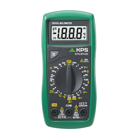
- Página 1 MANUAL DE INSTRUCCIONES INSTRUCTIONS MANUAL Multímetro digital Digital multimeter...
-
Página 2: Tabla De Contenido
CONTENIDOS CONTENIDOS ......... 1.Introducción ..........1 3.2.3 Corriente DC ............3.2.4 Corriente AC 1.1 Instrucciones de seguridad ..............1.1.1 Precauciones 3.2.5 Resistencia ........1.1.2 Símbolos de seguridad 3.2.6 Continuidad/prueba de diodos ............3.2.7 Test de temperatura 1.1.3 Mantenimiento 4. -
Página 3: Introducción
1.Introducción * Asegúrese de que los conectores de prueba están en los terminales de entrada correctos antes de realizar la medición. Este multímetro digital puede medir tensiones AC/DC, corriente AC/DC, * Elija la escala más alta cuando el valor que va a ser medido es resistencia, diodos, la tensión de la batería y temperatura. -
Página 4: Mantenimiento
Cumple con los estándares europeos de seguridad. (EU) Corriente alterna Corriente continua Conforme a UL STD. 61010-1, 61010-2-032, 61010-2-033; Certificado con CSA STD C22.2 NO. 61010-1, 61010-2-032,61010-2-033 CAT III (Categoría de medición III) : Aplicable para comprobar y medir circuitos conectados a la parte de distribución de la instalación de suministro de baja tensión del edificio. -
Página 5: Pantalla
.2 Pantalla 3. Especificaciones Pantalla LCD de 3 ½ dígitos y 15 3.1 Especificaciones generales Rango Función 2.3 Botón Hold * Presione para mantener la lectura actual en la pantalla. Categoría de seguridad 600V CAT III * Presione de nuevo para volver a la pantalla normal. Grado de contaminación 2.4 Rueda selectora Altitud de trabajo... -
Página 6: Especificaciones Técnicas
3.2 Especificaciones técnicas 3.2.3 Corriente DC Precisión: ±(% de lectura + dígitos) entre 18ºC y 28ºC con una Resolución Escala Precisión humedad relativa de <80%; garantizada por un periodo 1µA de un año. ±(1.0% de lectura + 3 dígitos) 20mA 10µA 3.2.1 Tensión DC 10mA... -
Página 7: Continuidad/ Test Diodo
4. Instrucciones de funcionamiento 3.2.6 Continuidad/ Test Diodo 4.1 Tensión DC/AC Descripción Función ADVERTENCIA Si la resistencia medida Voltaje del circuito Voltaje máximo de entrada: 600V DC o AC rms (en la escala es menor a 50Ω, emitirá abierto: 2.8V 200mV es 250V DC o AC rms). -
Página 8: Corriente Dc/Ac
Nota: 4.4 Diodos ADVERTENCIA * Cuando la resistencia medida sea mayor que 1MΩ, espere durante unos segundos para que se estabilice la lectura. Esto es normal en Apague la alimentación y descargue todos los condensadores mediciones de alta resistencia. completamente antes de realizar la comprobación de diodos. * Cuando el circuito esté... -
Página 9: Temperatura
5. Mantenimiento 4.6 Temperatura ADVERTENCIA 5.1 Limpieza del multímetro Apague la alimentación y descargue todos los condensadores ADVERTENCIA antes de realizar las mediciones de temperatura. Antes de abrir la tapa trasera, apague el multímetro y * Gire la rueda selectora a la posición ºC o ºF. La pantalla desconecte los cables de prueba de cualquier circuito. -
Página 10: Cambio De La Pila Y Fusibles
Asegúrese de que la tapa trasera está correctamente atornillada antes de utilizar el instrumento. KPS SOLUCIONES EN ENERGÍA, S.L. Parque Empresarial de Argame, C/Picu Castiellu, Parcelas i-1 a i-3 E-33163 Argame, Morcín... - Página 11 CONTENTS CONTENTS ......... 1.Introduction ..........1 3.2.3 DC Current ..............3.2.4 AC Current 1.1 Safety Guidelines ..............1.1.1 Precautions 3.2.5 Resistance ........... 1.1.2 Safety Symbols 3.2.6 Continuity/Diode Test ............3.2.7 Temperature Test 1.1.3 Maintenance 4. Operating Instructions 2.Instrument Description ......3 ......10 ........
-
Página 12: Introduction
1.Introduction • Make sure the test leads are in the correct input jacks before measurement. This digital multimeter can measure AC/DC voltage, • Choose the highest range when the value to be measured is AC/DC current, resistance, diode, the voltage of battery, unknown beforehand. -
Página 13: Maintenance
Complies with European (EU) safety standards Alternating current Direct current Conforms to UL STD. 61010-1, 61010-2-032, 61010-2-033; Certified to CSA STD C22.2 NO. 61010-1, 61010-2-032,61010-2-033 CAT III (MEASUREMENT CATEGORY III): It is applicable to test and measuring circuits connected to the distribution part of the building’s low-voltage MAINS installation. -
Página 14: Hold Button
2.2 Display 3. Specifications 3 ½ digit, 15mm LCD display 3.1 General Specifications 2.3 Hold Button Range Function Press to keep the current reading on the display. • Safety Rating 600V CAT III Press the button again to return to normal display. •... -
Página 15: Technical Specifications
3.2 Technical Specifications 3.2.3 DC Current Accuracy: ±(% of reading + digits) at 18°C~28°C with a Measuring range Accuracy Resolution relative humidity of <80%; guaranteed for a period of 1µA one year. ±(1.0% of reading +3 digits) 20mA 10µA 3.2.1 DC Voltage ±(2.0% of reading +5 digits) 10mA Measuring range... -
Página 16: Continuity/Diode Test
4. Operating Instructions 3.2.6 Continuity/Diode Test 4.1 DC/AC Voltage Description Function Warning If measured resistance Open circuit voltage: Max. input voltage: 600V DC or AC rms (200mV is less than 50Ω, the approx. 2.8V range is 250V DC or AC rms). buzzer will sound. -
Página 17: Dc/Ac Current
Note: 4.4 Diodes • When the measured resistance is greater than 1MΩ, Warning wait a few seconds for readings to stabilize.This is Turn off all power and discharge all capacitors normal for high resistance measurements. completely before testing diodes. • When the circuit is open or leads not connected, the display will show “1”. - Página 18 Note: 4.4 Diodes • When the measured resistance is greater than 1MΩ, Warning wait a few seconds for readings to stabilize.This is Turn off all power and discharge all capacitors normal for high resistance measurements. completely before testing diodes. • When the circuit is open or leads not connected, the display will show “1”.
-
Página 19: Temperature
5. Maintenance 4.6 Temperature 5.1 Cleaning the Meter Warning Turn off all power and discharge all capacitors Warning completely before testing temperature. Before opening the back cover, turn off the meter • Turn the rotary switch to the °C or °F position.The and disconnect test leads from any circuit. -
Página 20: Replacing The Battery And Fuses
To avoid electric shock, make sure the probes are disconnected from the measured circuit before removing the rear cover. Make sure the rear cover is tightly screwed before using the instrument. KPS SOLUCIONES EN ENERGÍA, S.L. Parque Empresarial de Argame, C/Picu Castiellu, Parcelas i-1 a i-3 E-33163 Argame, Morcín...