Tabla de contenido
Publicidad
Idiomas disponibles
Idiomas disponibles
Enlaces rápidos
IS227 Rev00 03/10/2019
B70/1DCHP/S1
centrale di comando 36V per cancelli scorrevoli
Istruzioni originali
IT
Istruzioni ed avvertenze per l'installatore
Instructions and warnings for the installer
EN
Anweisungen und Hinweise für den Installateur
DE
Instructions et consignes pour l'installateur
FR
Instrucciones y advertencias para el instalador
ES
Instruções e advertências para o instalador
PT
Aanwijzingen en waarschuwingen voor de installateur
NL
PL
Publicidad
Capítulos
Tabla de contenido

Manuales relacionados para Roger Technology B70/1DCHP/S1


Resumen de contenidos para Roger Technology B70/1DCHP/S1
- Página 1 IS227 Rev00 03/10/2019 B70/1DCHP/S1 centrale di comando 36V per cancelli scorrevoli Istruzioni originali Istruzioni ed avvertenze per l’installatore Instructions and warnings for the installer Anweisungen und Hinweise für den Installateur Instructions et consignes pour l’installateur Instrucciones y advertencias para el instalador Instruções e advertências para o instalador...
-
Página 3: Tabla De Contenido
Indice • Index • Index • Indice • Índice • Índice Avvertenze generali Allgemeine Sicherheitshinweise Dichiarazione CE di Conformità Konformitätserklärung Simbologia Symbole Descrizione prodotto Produktbeschreibung Caratteristiche tecniche prodotto Technische Daten des Produkts Descrizione dei collegamenti Beschreibung der Anschlüsse Installazione tipo Art der Installation Collegamenti elettrici Elektrische Anschlüsse... - Página 4 Advertencias generales Algemene waarschuwingen Declaración CE de Conformidad EG-verklaring van overeenstemming Símbolos Symbolen Descripción del producto Beschrijving product Características técnicas del producto Technische kenmerken product Descripción de las conexiones Beschrijving aansluitingen Instalación básica Type installatie Conexiones eléctricas Elektrische aansluitingen Comandos y accesorios Bedieningen en accessoires Teclas de función y pantalla Functietoetsen en display...
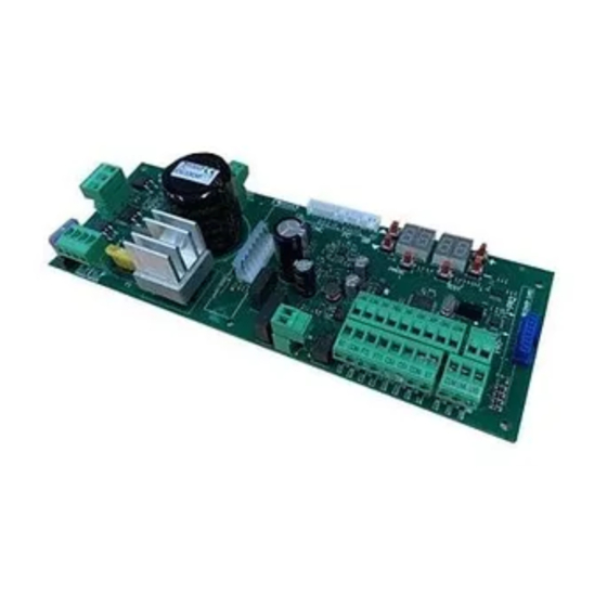
- Página 5 H1.02 (non utilizzato) e contatto di sblocco Plug for encoder, limit switch (not used) and unlock microswitch connection Connettore scheda carica Display a 4 cifre e 6 tasti di Collegamento batterie batterie programmazione Batteries connection Plug for battery charger 4 digit display and 6 programming buttons Microcontrollore Collegamento...
-
Página 7: Power Supply
FUSIBILE FUSE FUSIBILE FUSE FUSIBILE FUSE Alimentazione Power supply BATTERY CHARGER +LAM +24V COS2 COS1 H93/RX22A/I RICEVITORE RADIO RADIO RECEIVER... - Página 8 Luce di cortesia Courtesy light 230Vac 100W marrone brown blue marrone brown FUSIBILE FUSE max 1A +LAM Spia cancello aperto Lampeggiante Open gate light Flashing light 24Vdc 3W 24Vdc max 25W +24V Apertura parziale Partial opening COS2 Passo passo Bordo sensibile 2 Step by step Safety edge 2 COS1...
- Página 9 COLLEGAMENTO CON 1 COPPIA FOTOCELLULE SINCRONIZZABILI CONNECTION WITH 1 PAIR OF SYNCHRONOUS PHOCELLS USO RACCOMANDATO per fotocellule Serie F4ES - F4S RECOMMENDED USE for Series F4ES - F4S photocells MASTER 1 2 3 3 4 5...
- Página 10 COLLEGAMENTO CON 2 COPPIE FOTOCELLULE SINCRONIZZABILI CONNECTION WITH 2 PAIRS OF SYNCHRONOUS PHOCELLS 3 4 5 1 2 3 MASTER SLAVE 1 1 2 3 4 5 1 2 3 USO RACCOMANDATO per fotocellule Serie F4ES - F4S RECOMMENDED USE for Series F4ES - F4S photocells nero black...
- Página 11 TEST FOTOCELLULE · PHOTOCELLS TEST ( COLLEGAMENTO CON 1 COPPIA FOTOCELLULE SINCRONIZZABILI CONNECTION WITH 1 PAIR OF SYNCHRONOUS PHOCELLS USO RACCOMANDATO per fotocellule Serie F4ES - F4S RECOMMENDED USE for Series F4ES - F4S photocells MASTER 3 4 5 1 2 3...
- Página 12 TEST FOTOCELLULE · PHOTOCELLS TEST ( COLLEGAMENTO CON 2 COPPIE FOTOCELLULE SINCRONIZZABILI CONNECTION WITH 2 PAIRS OF SYNCHRONOUS PHOCELLS USO RACCOMANDATO per fotocellule Serie F4ES - F4S RECOMMENDED USE for 1 2 3 1 2 3 4 5 Series F4ES - F4S photocells MASTER 1 2 3 4 5 1 2 3...
- Página 13 BATTERY SAVING ( BATTERY SAVING + TEST FOTOCELLULE · PHOTOCELLS TEST ( COLLEGAMENTO CON 1 COPPIA FOTOCELLULE SINCRONIZZABILI CONNECTION WITH 1 PAIR OF SYNCHRONOUS PHOCELLS USO RACCOMANDATO per fotocellule Serie F4ES - F4S RECOMMENDED USE for Series F4ES - F4S photocells 1 2 3 1 2 3 4 5 MASTER...
- Página 14 BATTERY SAVING ( BATTERY SAVING + TEST FOTOCELLULE · PHOTOCELLS TEST ( COLLEGAMENTO CON 2 COPPIE FOTOCELLULE SINCRONIZZABILI CONNECTION WITH 2 PAIRS OF SYNCHRONOUS PHOCELLS USO RACCOMANDATO per fotocellule Serie F4ES - F4S 1 2 3 4 5 1 2 3 RECOMMENDED USE for Series F4ES - F4S photocells MASTER...
- Página 15 PR1 PR2...
- Página 16 Nero/Black (26 Vac) Blu/Blue (19 Vac)
- Página 17 BG30 High Speed MOTOR Marrone Brown Cavo motore Motor cable B72/BRAKE2...
- Página 18 BATTERY B71/BCHP BATTERY CHARGER BATTERY FC SB PROG TEST SEC2 SEC1 10 11 12 13 14 15 16 17 18 TRANSFORMER BLACK FUSE T10A 5x20 2 x 12V 4,5Ah AGM Battery ONLY...
-
Página 19: Avvertenze Generali
La mancata osservanza delle informazioni contenute nel presente manuale può dare luogo a infortuni personali o danni all’apparecchio. ROGER TECHNOLOGY declina qualsiasi responsabilità derivante da un uso improprio o diverso da quello per cui è destinato ed indicato nel presente manuale. - Página 20 EN 12453 e EN 12445. ROGER TECHNOLOGY declina ogni responsabilità qualora vengano installati In caso sia attiva la funzione uomo presente dovrà essere cura dell’installatore deformabile in gomma, la velocità di chiusura del varco ed in generale garantisca il controllo e il funzionamento dell’automazione e che il tipo di...
-
Página 21: Dichiarazione Ce Di Conformità
È necessario conservare queste istruzioni e trasmetterle ad eventuali subentranti nell’uso dell’impianto. Dichiarazione CE di Conformità DICHIARA che la centrale di comando B70/1DCHP/S1 è conforme ai requisiti essenziali e alle altre disposizioni – 2014/35/EU Direttiva LVD – 2014/53/EU Direttica RED... -
Página 22: Simbologia
RAEE, vedere capitolo 22. Descrizione prodotto La centrale di comando digitale B70/1DCHP/S1 a 36 V utilizza il controllo di potenza motore in modalità sensored, ROGER TECHNOLOGY declina qualsiasi responsabilità derivante da un uso improprio o diverso da quello per cui è destinato ed indicato nel presente manuale. -
Página 23: Caratteristiche Tecniche Prodotto
La somma degli assorbimenti di tutti gli accessori collegati non deve superare i dati di potenza massima indicati in tabella. I dati sono garantiti SOLO con accessori originali ROGER TECHNOLOGY. L'utilizzo di accessori non originali può causare malfunzionamenti. ROGER TECHNOLOGY declina ogni responsabilità per installazioni errate o non conformi. -
Página 24: Descrizione Dei Collegamenti
Descrizione dei collegamenti Installazione tipo Le informazioni riportate in tabella sono indicative, è responsabilità dell'installatore alle loro caratteristiche tecniche. Cavo consigliato Alimentazione di rete. Cavo a doppio isolamento tipo H07RN-F 3x1,5 mm Fotocellula - Ricevitore F4ES/F4S Cavo 5x0,5 mm (massimo 20 m) Fotocellula - Trasmettitore F4ES/F4S Cavo 3x0,5 mm (massimo 20 m) -
Página 25: Collegamenti Elettrici
±10%) Fusibile 5x20 T2A. Ingresso secondario del trasformatore per alimentazione motore 26 Vac (SEC1) e per alimentazione logica e periferiche 19 Vac (SEC2). NOTA: Il cablaggio è realizzato di fabbrica da ROGER TECHNOLOGY. SEC2 SEC1 X-Y-Z Collegamento B72/BRAKE/2 per versioni BG30 NOTA: I cablaggi sono realizzati di fabbrica da ROGER TECHNOLOGY. -
Página 26: Comandi E Accessori
Comandi e accessori disabilitate modificando i parametri N.A. (Normalmente Aperto) . N.C. (Normalmente Chiuso). CONTATTO DESCRIZIONE 9(COR) Collegamento luce di cortesia (contatto puro) 230 Vac 100 W - 24 Vac/dc 40 W. NOTA: Prevedere un fusibile a protezione. 9(COR) • cancello sbloccato / anomalia nell'alimentazione da batteria (batteria in esaurimento); •... - Página 27 CONTATTO DESCRIZIONE 24(ORO) 23(COM) Ingresso contatto temporizzato orologio (N.A.). Quando si attiva la funzione orologio il cancello apre e rimane aperto per il tempo programmato dall'orologio. Allo scadere del tempo programmato dal dispositivo esterno (orologio) il cancello chiude. Il funzionamento del comando è regolato dal parametro 25(AP) 23(COM) Ingresso comando di apertura (N.A.).
-
Página 28: Tasti Funzione E Display
Tasti funzione e display TASTO DESCRIZIONE Parametro successivo Parametro precedente DOWN DOWN Incremento di 1 del valore del parametro Decremento di 1 del valore del PROG TEST parametro PROG Apprendimento della corsa TEST Attivazione modalità TEST • Premere i tasti UP e/o DOWN •... -
Página 29: Modalità Visualizzazione Di Stato Comandi E Sicurezze
Modalità visualizzazione di stato comandi e sicurezze STATO DELLE SICUREZZE COS1 COS2 POWER STOP STATO DEI COMANDI: Le indicazioni dei comandi sono normalmente SPENTE. Si ACCENDONO accende il segmento PP). SEGMENTO COMANDO apre passo-passo chiude apertura parziale orologio STATO DELLE SICUREZZE: Le indicazioni delle sicurezze sono normalmente ACCESE. -
Página 30: Modalità Test
Modalità TEST La modalità si attiva premendo il tasto TEST ad automazione ferma. Se il cancello è in movimento, il tasto TEST provoca uno STOP. La successiva pressione abilita la modalità di TEST. Il lampeggiante e la spia cancello aperto si accendono per un secondo. Il display visualizza a sinistra, per 5 s, lo stato dei comandi SOLO se attivi, ( Esempio se si attiva il comando di apertura, sul display appare... -
Página 31: Apprendimento Della Corsa
Apprendimento della corsa Per un corretto funzionamento, è necessario eseguire l’apprendimento della corsa. 10.1 Prima di procedere Motore HIGH SPEED TIPO SELEZIONE MODELLO CONFIGURAZIONI MOTORE Vedi capitolo 13 "Parametri speciali per FISSA BG30/1800/HS High Speed" 1. Selezionare la posizione del motore rispetto al varco con il parametro . -
Página 32: Procedura Di Apprendimento
10.2 Procedura di apprendimento PROG FO TO AP P- PH A5 PH A5 AU to x4 s (appare se FT Aspetta ... collegate e abilitate) Sì AU to APERTURA APERTO CHIUSURA CHIUSO • Premere il tasto PROG per 4 s, sul display appare •... -
Página 33: Indice Dei Parametri
Indice dei parametri PARAM. VALORE DI DESCRIZIONE PAGINA FABBRICA Richiusura automatica dopo il tempo di pausa (da cancello completamente aperto) Selezione funzionamento comando passo-passo (PP) Prelampeggio Funzione condominiale sul comando di apertura parziale (PED) Abilitazione funzione a uomo presente Spia cancello aperto/funzione test fotocellule e "battery saving" Regolazione del rallentamento in apertura Regolazione del rallentamento in chiusura Regolazione dello spazio di accostamento alla battuta di apertura a velocità... - Página 34 PARAM. VALORE DI DESCRIZIONE PAGINA FABBRICA Selezione della posizione di installazione del motore rispetto al varco, vista lato interno Selezione modalità di funzionamento luci di cortesia Abilitazione della chiusura/apertura garantita Regolazione tempo di attivazione della chiusura/apertura garantita Selezione gestione funzionamento a batteria Selezione delle limitazioni nel funzionamento a batteria Selezione del tipo di batteria e riduzione dei consumi Ripristino ai valori standard di fabbrica...
-
Página 35: Menù Parametri
Menù parametri VALORE DEL Richiusura automatica dopo il tempo di pausa (da cancello completamente aperto) Disabilitata. Da 1 a 15 tentativi di richiusura dopo l’intervento delle fotocellule. Scaduto il numero di tentativi impostato, il cancello rimane aperto. Il cancello prova a chiudere illimitatamente. Richiusura automatica dopo interruzione di alimentazione di rete (black-out) Disabilitata. - Página 36 te aperto. Lampeggia velocemente durante la manovra di chiusura. Se il cancello è fermo in posizione intermedia, la spia si spegne due volte ogni 15 s. Impostare a se l’uscita SC Impostare a se l’uscita SC Quando il cancello è completamente aperto o completamente chiuso, la centralina disattiva gli accessori collegati al morsetto SC per ridurre il consumo di batteria.
- Página 37 Tolleranza sulla battuta di apertura. 02= tolleranza minima (giri rotore) ... 10= tolleranza massima (giri rotore) Tolleranza sulla battuta di chiusura. 02= tolleranza minima (giri rotore) ... 10= tolleranza massima (giri rotore) Anticipo sull'arresto in completa apertura. 02= anticipo minimo (giri rotore) ... 15= anticipo massimo (giri rotore) Anticipo sull'arresto in completa chiusura.
- Página 38 L’intervento del rilevamento ostacolo è regolato dai valori impostati dai parametri e dal valore di corrente massima memorizzata in fase di apprendimento della corsa. L’intervento del rilevamento ostacolo è il 70% della coppia massima per un tempo di intervento di 1 s. L’intervento del rilevamento ostacolo è...
-
Página 39: Selezione Della Posizione Di Installazione Del Motore Rispetto Al Varco, Vista Lato Interno
INVERSIONE RITARDATA. Con fotocellula oscurata il cancello si ferma. Liberata la fotocellula il cancello apre. Modalità di funzionamento della fotocellula (FT2) con cancello chiuso Il parametro non è visibile se Se la fotocellula è oscurata il cancello non può aprire. Il cancello si apre al ricevimento di un comando di apertura anche se la fotocellula è... -
Página 40: Selezione Modalità Di Funzionamento Luci Di Cortesia
attivo. Il parametro viene ignorato. Luce di cortesia passo-passo (PP). L’uscita COR viene gestita dal radiocomando. Il radiocomando accende-spegne la luce di cortesia. Il parametro viene ignorato. PASSO PASSO con conferma di sicurezza APERTURA PARZIALE con conferma di sicurezza APERTURA con conferma di sicurezza CHIUSURA con conferma di sicurezza Per evitare che la pressione involontaria di un tasto del radiocomando attivi erroneamente il cancello, viene richiesta una confer- •... -
Página 41: Selezione Delle Limitazioni Nel Funzionamento A Batteria
Il controllo si attiva quando la tensione di batteria scende alla soglia minima (22Vdc per batteria 2x12Vdc) Il controllo si attiva quando la tensione di batteria scende alla soglia intermedia (23Vdc per batteria 2x12Vdc) Il controllo si attiva quando la tensione di batteria scende alla soglia massima (24Vdc per batteria 2x12Vdc) Selezione delle limitazioni nel funzionamento a batteria. -
Página 42: Visualizzazione Contatore Ore Manovra
Visualizzazione contatore ore manovra Il numero è composto dai valori dei parametri da NOTA Ore manovra = 123 ore Visualizzazione contatore giorni di accensione della centralina Il numero è composto dai valori dei parametri da NOTA Giorni di accensione = 123 giorni Password L’impostazione della password impedisce l’accesso alle regolazioni a personale non autorizzato. -
Página 43: Parametri Speciali Serie High Speed
Parametri speciali serie HIGH SPEED High Speed alta velocita per i cancelli scorrevoli, esclusivamente dedicati al settore residenziale e industriale. La tecnologia High Speed consente di gestire l'automazione al 100% più velocemente delle automazioni tradizionali con la possibilità di gestire separatamente velocità, accelerazione, rallentamenti e relative sicurezze. -
Página 44: Segnalazione Degli Ingressi Di Sicurezza E Dei Comandi (Modalità Test)
Segnalazione degli ingressi di sicurezza e dei comandi (modalità TEST) DISPLAY POSSIBILE CAUSA INTERVENTO DA SOFTWARE INTERVENTO TRADIZIONALE La maniglia di sblocco è aper- Chiudere la maniglia di sblocco e girare la chiave in posizione di chiu- (Sb) sura. di sblocco. Contatto STOP di sicurezza Installare un pulsante di STOP (N.C.) aperto. -
Página 45: Segnalazione Allarmi E Anomalie
Segnalazione allarmi e anomalie SEGNALAZIONE PROBLEMA POSSIBILE CAUSA INTERVENTO ALLARME LED POWER spento LED POWER spento Fusibili bruciati. Sostituire il fusibile. Si raccomanda di estrarre e reinserire il fusibile sola- mente in assenza di tensione di rete. Anomalia nella tensione Togliere alimentazione, attendere 10 s e ridare ali- di alimentazione di in- mentazione. - Página 46 SEGNALAZIONE PROBLEMA POSSIBILE CAUSA INTERVENTO ALLARME Premere il tasto TEST, se la segnalazione di errore dell’encoder. persiste, sostituire l’encoder. (EnE5) Alimentazione da rete Nel caso ci sia presenza di sporco, umidità, insetti o altro, togliere l’alimentazione e pulire l'encoder e la scheda.
-
Página 47: Diagnostica - Modalità Info
TEST PER USCIRE 1 click DALLA MODALITA’ x5 s B70/1DCHP/S1. Dalla modalità “Visualizzazione comandi e sicurezze” e con motore fermo, premere per 5 s il tasto TEST. Parametro Funzione totale. = motore installato a sinistra = motore installato a destra assorbita. -
Página 48: Sblocco Meccanico
Sblocco meccanico In caso di guasto o in mancanza di tensione, è possibile sbloccare il cancello e movimentarlo a mano. Per ulteriori informazioni consultare l'operazione di blocco/sblocco sul manuale d'uso dell'automazione. Se si sblocca il cancello con la centralina alimentata, sul display appare lampeggiante. -
Página 49: Messa In Funzione
Informazioni aggiuntive e contatti Tutti i diritti relativi alla presente pubblicazione sono di proprietà esclusiva di ROGER TECHNOLOGY. Il formato digitale (PDF) e tutti gli eventuali aggiornamenti futuri, sono disponibili nell’area riservata del nostro sito... -
Página 50: General Safety Precautions
ROGER TECHNOLOGY is not liable for failure to observe the good practices occur during use. The safety devices (photocells, sensing edges, emergency stops, etc.) must... - Página 51 The installer is required to measure impact forces and select on the control unit the appropriate speed and torque values to ensure that the door or gate ROGER TECHNOLOGY cannot be held responsible for any damage or injury caused by the installation of incompatible components which compromise the safety and correct operation of the device.
-
Página 52: Declaration Ce Of Conformity
Declaration CE of Conformity The undersigned Dino Florian, legal representative of Roger Technology - Via Botticelli 8, 31021 Mogliano V.to (TV) DECLARES that the B70/1DCHP/S1 digital control unit is compliant with the provisions established by – 2014/35/EU LVD Standard – 2014/53/EU RED Standard... -
Página 53: Symbols
22. Product description The B70/1DCHP/S1 36 V digital control unit uses a high resolution encoder for the sensored power control of ROGER sliding gate leaf automation systems. ROGER TECHNOLOGY cannot be held responsible for any damage or injury due to improper use or any use other than the intended usage indicated in this manual. -
Página 54: Technical Characteristics Of Product
The total of the absorption values of all the accessories connected must not exceed the maximum power values shown in the table. The values are guaranteed with original ROGER TECHNOLOGY accessories ONLY. The use of non-original accessories may lead to malfunctioning. ROGER TECHNOLOGY declines all responsibility for incorrect or non-conforming installations. -
Página 55: Description Of Connections
Description of connections To access the control connection terminal board, remove the motor cover as shown in Figure 2-3-4-5 shows connection diagrams for connecting mains voltage to the motor control unit Typical installation It is the installer's responsibility to verify the adequacy of the cables in relation to the devices used in the installation and their technical characteristics. -
Página 56: Electrical Connections
Fuse 5x20 T2A. Secondary transformer input for 26 V AC motor power (SEC1) and for 19 V power to logical control and peripheral devices (SEC2). N.B.: Ready wired in factory by ROGER TECHNOLOGY. SEC2 SEC1 Connection to ROGER brushless motor. -
Página 57: Commands And Accessories
If the sensing edge is not installed, jumper the terminals 15(COS1) - 16(COM) or set the pa- rameter 17(ST) 16(COM) STOP command input (NC). The current manoeuvre is arrested if the safety contact opens. N.B.: the controller is supplied with this contact already jumpered by ROGER TECHNOLOGY. 21(ANT) Antenna connector for slot-in radio receiver board. N.B. - Página 58 (see chapter 18). N.B.: Ready wired in factory by ROGER TECHNOLOGY. RECEIVER CARD Connector for plug-in radio receiver board.
-
Página 59: Function Buttons And Display
Function buttons and display BUTTON DESCRIPTION Next parameter Previous parameter DOWN DOWN Increase value of parameter by 1 Decrease value of parameter by 1 PROG Travel acquisition PROG TEST TEST Activate TEST mode • Press the UP and/or DOWN buttons to view the parameter you intend to modify. •... -
Página 60: Command And Safety Device Status Display Mode
Command and safety device status display mode SAFETY DEVICE STATUS COS1 COS2 POWER STOP COMMAND STATUS: The command status indicators on the display are normally OFF. illuminates). SEGMENT COMMAND open step-by-step mode close partial opening SAFETY DEVICE STATUS: The safety device status indicators ON the display . If an indicator is OFF, the relative device is in alarm state or is not connected. -
Página 61: Test Mode
TEST mode To activate the mode, press the TEST button with the automatic door system at rest. If the gate is moving, pressing TEST stops the gate. Pressing the button again enables TEST mode. safety device is activated. The command signal status is shown on the left hand side of the display for 5 seconds, ONLY when the respective command signal is active ( ). -
Página 62: Travel Acquisition
Travel acquisition For the system to function correctly, the gate travel must be acquired by the control. 10.1 Before starting HIGH SPEED Motor MOTOR SELECTION MODEL CONFIGURATIONS TYPE up to 1800 see chapter 13 "Special Parameters for FIXED BG30/1800/HS High Speed Motor" 1. -
Página 63: Acquisition Procedure
10.2 Acquisition procedure: PROG FO TO AP P- PH A5 PH A5 AU to x4 s Wait ... (if FT are connected or enabled) AU to OPENING OPEN CLOSING CLOSE • Press and hold PROG for 4 seconds. is shown on the display. •... -
Página 64: Parameter's Index
Parameter's index FACTORY PARAM. DESCRIPTION PAGE VALUE Automatic closure after pause time (from gate completely open) Automatic gate closing after mains power outage Selecting step mode control function (PP) Condominium function for partial open command (PED) Enabling operator present function. Gate open indicator / photocell test function and “battery saving”... -
Página 65: Param
FACTORY PARAM. DESCRIPTION PAGE VALUE Selecting courtesy light mode Enable safeguarded gate closure/opening. Setting safeguarded closure/opening activation time Selection of the battery operation management Selection of the battery operation limitations Selection of the battery type and consumption reduction Restoring factory default values HW version. -
Página 66: Parameter Menu
Parameter menu VALUE Automatic closure after pause time (from gate completely open) Disabled. From 1 to 15 of gate closure attempts after photocell is triggered. Once the number of attempts set is reached, the gate remains open. Automatic gate closing after mains power outage Disabled. -
Página 67: Setting Deceleration During Opening
If the gate is stopped in an intermediate position, the lamp extinguishes twice every 15 seconds. if the output SC Set to if the output SC When the gate is completely open or closed, the controller unit deactivates any accessories connected to terminal SC to reduce battery consumption. -
Página 68: Tolerance On The Closing Stop
Tolerance on the closing stop. 02= minimum tolerance (engine revs) ... 10= maximum tolerance (engine revs) Advance on stop in full opening. 02= minimum advance (engine revs) ... 15= maximum advance (engine revs) Advance on stop in full closing. 02= minimum advance (engine revs) ... 15= maximum advance (engine revs) Setting reverse time after activation of sensing edge or obstacle detection (crush prevention). -
Página 69: Setting Number Of Automatic Closure Attempts After Activation Of Sensing
The response of the obstacle detection system is a 70% reduction in maximum torque for a period of 1 s. The response of the obstacle detection system is a 80% reduction in maximum torque for a period of 2 s. The response of the obstacle detection system is a 100% reduction in maximum torque for a period of 3 s. -
Página 70: Photocell (Ft2) Mode With Gate Closed
STOP. The gate stops and remains stationary until the next command is received. photocell is cleared. DELAYED REVERSE. The gate stops if the photocell is obstructed. The gate opens when the photocell is cleared. Photocell (FT2) mode with gate closed This parameter is not visible if is set. - Página 71 Courtesy light in step mode (PP). The output COR is managed from the remote control. The remote control turns the courtesy light on and off. The parameter is ignored. • Selecting courtesy light mode Disabled. ACTIVE. The light remains lit for the entire duration of the manoeuvre. From 3 to 90 s.
- Página 72 The command becomes active when the battery voltage drops to the minimum threshold (22Vdc for battery 2x12Vdc) The command becomes active when the battery voltage drops to the medium threshold (23Vdc for battery 2x12Vdc) The command becomes active when the battery voltage drops to the maximum threshold (24Vdc for battery 2x12Vdc) Selecting the battery operation limitations.
-
Página 73: Changing Password
Manoeuvres performed. x100 = 1.234.500 manoeuvres. View manoeuvre hour counter The number consists of the values of the parameters from N.B. Manoeuvre hours. = 123 hours. View control unit days on counter The number consists of the values of the parameters from N.B. -
Página 74: Special Parameters For High Speed Series
Special parameters for HIGH SPEED series applications. conventional system, and allows independent management of speed, acceleration, deceleration and the safety devices used in the system. Note: As the mechanics of the gate is unknown, to guarantee the maximum safety of the installation, we recommended to use sensitive edges. -
Página 75: Safety Input And Command Status (Test Mode)
Safety input and command status (TEST mode) DISPLAY POSSIBLE CAUSE ACTION BY SOFTWARE PHYSICAL CORRECTIVE ACTION The release handle is open. Close the release handle and turn the (Sb) nected correctly. The safety STOP contact is open. Install a STOP button (NC) or jumper Sensing edge COS1 not connected Set the parameter Jumper contact COS1 with contact... -
Página 76: Alarms And Faults
Alarms and faults PROBLEM ALARM POSSIBLE CAUSE ACTION LED POWER off No power. LED POWER off Fuses blown. Replace fuses. Always disconnect from mains power before removing fuses. Input mains power voltage fault. Disconnect from mains power, wait 10 seconds then reconnect to the mains and switch on. - Página 77 PROBLEM ALARM POSSIBLE CAUSE ACTION Encoder calculation error. Repeat acquisition procedure. Inverter thermal overload circuit Function is restored automatically within 2 min. The gate does not Flat batteries. Wait for mains power to be restored. open or close. (btLO) Release device open. connected correctly.
- Página 78 INFO MODE x5 s INFO mode may be used to view certain parameters measured by the B70/1DCHP/S1 controller. Press and hold the TEST button for 5 seconds from the “View command signals and safety devices” mode with the motor stationary.
-
Página 79: Mechanical Release
Mechanical release In the event of a fault or mains power loss, the gate may be released and opened manually. For further information, refer to the locking/release operation in the manual of the automation system. If the gate releases with the controller unit powered, the message When the release system is restored to the normal operating position, if the gate is not completely open or completely closed the next time a command is received, the control initiates a position recovery procedure (see chapter 18). -
Página 80: Start-Up
Warning! Some parts of this product may contain substances that are harmful to the environment or dangerous Additional information and contact details ROGER TECHNOLOGY is the exclusive proprietor holder of all rights regarding this publication. scanning or any alterations to this document are prohibited without express prior authorised from by ROGER TECHNOLOGY. -
Página 81: Allgemeine Sicherheitshinweise
Übereinstimmung der geltenden Richtlinien ausgeführt vorzunehmen, um Sicherheits- und Schutzzonen zu schaffen bzw. alle ROGER TECHNOLOGY ist weder für die Einhaltung der fachgerechten Die Sicherheitseinrichtungen (Fotozellen, Sicherheitsleisten, Notstopps den geltenden Vorschriften und Richtlinien, den fachgerechten Kriterien, der von der motorisierten Tür oder dem Tor ausgehen. - Página 82 Gefahren verursachen. Sicherheitsleisten am beweglichen Teil installieren. der Normen EN 12604 und EN 12453 erfüllt und gegebenenfalls auch überprüft werden müssen. bzw. das motorisierte Tor die von den Richtlinien EN 12453 und EN 12445 darauf hingewiesen, dass die Steuereinrichtung bei einer festen Anordnung 1 oder 2).
-
Página 83: Konformitätserklärung
Anlage übergeben werden. Konformitätserklärung Der Unterzeichnende Dino Florian, gesetzlicher Vertreter von Roger Technology - Via Botticelli 8, 31021 Mogliano V.to (TV) ERKLÄRT, dass die Steuerung B70/1DCHP/S1 mit den von den folgenden Gemeinschaftsrichtlinien – 2014/35/EU LVD Richtlinie – 2014/53/EU RED Richtlinie –... -
Página 84: Symbole
Wechselstrom (AC) Gleichstrom (DC) Richtlinie, siehe Kapitel 22. Produktbeschreibung Die digitale Steuereinheit B70/1DCHP/S1 werden, ab. Wir empfehlen die Verwendung von Zubehör, Steuer- und Sicherheitsvorrichtungen ROGER TECHNOLOGY. F4ES oder F4S zu installieren. Für weitere Informationen, siehe die Installationsanleitung der Automatisierung BG30/1800/HS. -
Página 85: Technische Daten Des Produkts
Technische Daten des Produkts B70/1DCPH/S1 (BG30/1800/HS) VERSORGUNGSSPANNUNG 230 V ± 10% 50 Hz MAXIMAL VOM STROMNETZ AUFGENOMMENE LEISTUNG 230 W ANLAUFLEISTUNG 650 W F1 = 20A (ATO257) SICHERUNGEN F2 = 3A (ATO257) Schutz der Zubehör Stromversorgung F3 = T2A (5x20 mm) ANSCHLIESSBARE MOTOREN STROMVERSORGUNG DES MOTORS 36 Vac, mit selbstschützendem Wechselrichter... -
Página 86: Beschreibung Der Anschlüsse
Beschreibung der Anschlüsse wie auf Abbildung 1 In Abbildung 2-3-4-5 Art der Installation überprüfen. Empfohlene Kabel Stromversorgung Kabel mit mit doppelt isolierten Typ H07RN-F 3x1,5 F4ES/F4S Kabel 5x0,5 mm 20 m) Sender F4ES/F4S Kabel 3x0,5 mm 20 m) R92/LED24 - FIFTHY/24 Kabel 2x1 mm 10 m) Stromversorgung 24V dc... -
Página 87: Elektrische Anschlüsse
Leitungen des Zubehörs (24 V) getrennt sind. BESCHREIBUNG Spannung Netzanschluss 230 Vac ±10% (115 Vac ±10%) . Sicherung 5x20 T2A. ANMERKUNG: Die Verkabelung erfolgt werkseitig von ROGER TECHNOLOGY. SEC2 SEC1 X-Y-Z Anschluss B72/BRAKE/2 für Ausführungen BG30 High Speed (Siehe Abb.13). -
Página 88: Befehle Und Zubehör
Befehle und Zubehör werden. KONTAKT BESCHREIBUNG 9(COR) Ausgang für Anschluss an die Zugangsbeleuchtung dc 40 W. HINWEIS: Eine Schutzsicherung vorsehen. 9(COR) • • gesteuert. eingestellt werden. 10(+SC) 11(COM) Anschluss Kontrollleuchte Tor offen 24 Vdc 3 W. geregelt. 10(+SC) 11(COM) Den Parameter Es ist außerdem möglich, die Stromversorgung aller externen Vorrichtungen anzuschließen, um oder einstellen. - Página 89 KONTAKT BESCHREIBUNG 24(ORO) 23(COM) das Tor schließt sich. geregelt. 25(AP) 23(COM) ACHTUNG der bei Loslassen des Öffnungsbefehls. 26(CH) 23(COM) Eingang Schließbefehl (Schließer). 27(PP) 23(COM) geregelt. 28(PED) 23(COM) 29(+24V) 30(COM) Siehe technische Daten. Versorgungsanschluss B72/BRAKE/2 für Ausführungen BG30 High Speed. 31(LAM) 30(COM) (24 Vdc - Einschaltdauer 50%).
-
Página 90: Funktionstasten Und Display
Funktionstasten und Display TASTE BESCHREIBUNG Vorangehender Parameter DOWN DOWN Erhöhung des Parameterwerts um 1 Verringerung des Parameterwerts um 1 PROG Programmierung des Torlaufs PROG TEST TEST • Die Tasten UP und/oder DOWN • + und - • Wenn man die Taste + oder die Taste - •... -
Página 91: Anzeigemodus Des Status Von Befehlen Und Sicherheitseinrichtungen
Anzeigemodus des Status von Befehlen und Sicherheitseinrichtungen STATUS DER SICHER- HEITSEINRICHTUNGEN COS1 COS2 POWER STOP STATUS DER BEFEHLE: sich das Segment PP ein). SEGMENTE BEFEHLE öffnet Schrittbetrieb schließt Teilöffnung STATUS DER SICHERHEITSEINRICHTUNGEN: Die Anzeigen der Sicherheitseinrichtungen sind normalerweise eingeschaltet. Sollten sie ausgeschaltet sein bedeutet dies, dass sie in Alarm oder nicht angeschlossen sind. SEGMENTE SICHERHEITSEINRICHTUNGEN COS1... -
Página 92: Test-Modus
TEST-Modus ). Wenn man Das Display zeigt auf der rechten Seite den Status der (Sb) Entriegelungsgriff oder Schloss offen. Überprüfen Sie die Verbindung. Überprüfen Sie die Verbindung. HINWEIS ersten der Alarm der zweiten und so weiter. Standby-Modus langsam. , DOWN , + , - HINWEIS: Wenn ein Passwort entsperrt wurde (nur wenn aktiv), POWER... -
Página 93: Einlernen Des Torlaufs
Einlernen des Torlaufs 10.1 Zunächst LEGENDE HIGH SPEED Motor AUSWAHL MODELL KONFIGURATIONEN MOTOR (siehe Kapitel 13 "Sonderparameter für FEST BG30/1800/HS High Speed). ÖFFNUNG NACH RECHTS ÖFFNUNG NACH LINKS OPEN CLOSE 3. Das Tor in die Schließstellung bringen. 4. Die Taste TEST TEST Siehe Kapitel 14 und 15 1 Klick... -
Página 94: Einlernverfahren
10.2 Einlernverfahren PROG FO TO AP P- PH A5 PH A5 AU to x4 s (ob FT angeschloßen Warte ... oder aktviert werden) AU to ÖFFNUNG GEÖFFNET SCHLIEßUNG GESCHLOSSEN • Die Taste PROG • . Die Steuereinheit beginnt ein • •... -
Página 95: Index Der Parameter
Index der Parameter STANDARD- PARAM. BESCHREIBUNG SEITE WERTE geöffnetem Tor) saving” Einstellung der Verlangsamung beim Öffnen Einstellung der Verlangsamung beim Schließen Einstellung Teilöffnung (%) Einstellung der automatischen Schließzeit erneuten Schließung. Toleranz am Öffnungsanschlag Toleranz am Schließanschlag. Einstellung Öffnungs Einstellung Schließungs Einstellung der Zahl der Versuche des automatischen Wiederschließens (Quetschschutz) - Página 96 STANDARD- PARAM. BESCHREIBUNG SEITE WERTE (Ansicht von der Innenseite) HW-Version Herstellungsjahr Herstellungswoche Seriennummer FW-Version Passwort...
-
Página 97: Menü Parameter
Menü Parameter WERT DES Automatische Schließung nach Auslösen nach der Pausenzeit (bei vollstän- dig geöffnetem Tor) Versuche bleibt das Tor offen. Das Tor versucht unbegrenzt zu schließen. Automatische Schließung nach einem Stromausfall (Blackout) eingestellten Wert). Das Wiederschließen erfolgt Funktionsauswahl Steuerbefehl Schrittbetrieb (PP) Öffnet-Stopp-Schließt-Stopp-Öffnet-Stopp-Schließt... - Página 98 und wenn das Tor geöffnet ist. Wenn das Tor in einer Zwischenposition stillsteht, schaltet sich die Kontrollleuchte zweimal alle 15 s aus. einstellen, wenn der Ausgang SC einstellen, wenn der Ausgang SC SC angesch- einstellen, wenn der Ausgang SC Abb. 9-10. Einstellung der Verlangsamung beim Öffnen und Schließen Siehe Kapitel 13 Einstellung des Annäherungswegs an der Öffnungsstopp mit konstanter Ge-...
-
Página 99: Einstellung Motordrehmoment
Toleranz am Öffnungsanschlag. Toleranz am Schließanschlag. Vorzeitiger Anhalten vor der vollständigen Öffnung. Vorzeitiger Anhalten vor der vollständigen Schließung. Einstellung der Umkehrzeit nach Auslösung der Sicherheitsleiste oder Erken- nung von Hindernissen (Quetschschutz). von 0 bis 60 s. Einstellung Motordrehmoment Wir empfehlen Werte unter verringern. - Página 100 Einstellung des Motordrehmoments während der Korrektur der Position Parametern auf. eingestellten Werte geregelt. stroms geregelt, der beim Einlernen des Torlaufs gespeichert wurde. Einstellung Öffnungsgeschwindigkeit und Schließungsgeschwindigkeit ANMERKUNG: Teile unterteilt. Siehe Kapitel 13 01= 6 m/min ... 10= Einstellung der konstanten Annäherungsgeschwindigkeit am Ende der Bewegung Weg ist von den Parametern geregelt.
- Página 101 Einstellung Funktionsweise der Lichtschranke beim Öffnen (FT2) das Tor sich. Einstellung Funktionsweise der Lichtschranke beim Schließen (FT2) Tor sich. Funktionsweise der Lichtschranke (FT2) bei geschlossenem Tor Der Parameter ist nicht sichtbar, wenn man oder einstellt. Aktivierung Schließbefehl 6 s nach Auslösen der Lichtschranke (FT1-FT2) Der Parameter ist nicht sichtbar, wenn man oder einstellt.
-
Página 102: Auswahl Funktionsweise Zugangsbeleuchtung
HINWEIS HINWEIS TEILÖFFNUNG ÖFFNUNG SCHLIESSUNG. STOPP. Zugangsbeleuchtung. Der Ausgang COR wird von der Fernbedienung gesteuert. Das Licht bleibt eingeschaltet, wird ignoriert. Zugangsbeleuchtung Schrittbetrieb (PP). Der Ausgang COR wird von der Fernbedienung gesteuert. Die Fernbedienung schaltet die Zugangsbeleuchtung ein-aus. Der Parameter wird ignoriert. -
Página 103: Wiederherstellung Der Werkseinstellungen
Parameter ) und das Tor schließt sich. sich nach einer vom Parameter eingestellten Zeit. sich nach einer vom Parameter eingestellten Zeit. Einstellung Aktivierungszeit der garantierten Schließung/Öffnung HINWEIS: Der Parameter wird nicht angezeigt, wenn der Parameter ist. von 2 bis 90 s Wartezeit Auswahl der Verwaltung im Batteriebetrieb Wenn ein anderer Wert als Parameter... - Página 104 Kennnummer Die Kennnummer besteht aus den Werten der Parameter von n0 bis n6. ANMERKUNG: Die in der Tabelle angegebenen Werte dienen nur zur Veranschaulichung. HW-Version. Herstellungsjahr. Herstellungswoche. Seriennummer. FW-Version. Anzeige Bewegungszähler Die Zahl besteht aus den Werten der Parameter von multipliziert mit 100.
-
Página 105: Sonderparameter Für Die Baureihe High Speed
Sonderparameter für die Baureihe HIGH SPEED Wohnbereich vorbehalten sind. Sicherheiten getrennt zu verwalten. ANMERKUNG: Die Mechanik des Tors nicht bekannt ist, um die maximale Sicherheit des Betriebes zu garantieren, empfehlen wir die Sicherheitsleiste zu installieren. Einstellung der Verlangsamung beim Öffnen Einstellung der Verlangsamung beim Schließen Einstellung Beschleunigung zu Beginn der Öffnungsbewegung Einstellung Beschleunigung zu Beginn der Schließenbewegung... -
Página 106: Meldung Der Sicherheitseingänge Und Der Befehle (Test- Modus)
Meldung der Sicherheitseingänge und der Befehle (TEST- Modus) MASSNAHME ÜBER HERKÖMMLICHE DISPLAY MÖGLICHE URSACHE SOFTWARE MASSNAHME Der Entriegelungsgriff ist Den Entriegelungsgriff schließen und den geöffnet. Schüssel in Schließstellung drehen. (Sb) überprüfen. Eine STOPP-Taste (Öffner) installieren geöffnet. Sicherheitsleiste COS1 Falls nicht benutzt oder man sie Falls nicht benutzt oder man sie aus- nicht oder falsch ange- ausschließen will, den Parameter... -
Página 107: Meldung Von Alarmen Und Störungen
Meldung von Alarmen und Störungen PROBLEM ALARMMELDUNG MÖGLICHE URSACHE BETRIEB ausgeschaltet Keine Stromversorgung. LED POWER ausgeschaltet Sicherung durchgebrannt. Sicherung ersetzen. LED POWER Die Sicherung nur bei ausgeschalteter Netzspan- nung herausziehen. Störung der Eingangsspan- Die Netzspannung ausschalten, 10 s warten und die nung. - Página 108 PROBLEM ALARMMELDUNG MÖGLICHE URSACHE BETRIEB Rechenfehler des Encoders. Das Einlernverfahren wiederholen. wiederhergestellt. Das Tor öffnet oder (btLO) schließt sich nicht. Entriegelungsvorrichtung Den Entriegelungsgriff schließen und den Schüssel geöffnet. in Schließstellung drehen. Den Anschluss an den Das Einlernverfahren wiederholen. fehlgeschlagen. Wenn das Problem weiter besteht, das Verbin- Prüfen, ob der Entriegelungsgriff geöffnet ist.
-
Página 109: Diagnostik - Betriebsart Info
TEST AUS DER TEST BESTRIEBSART 1 Klick ZU GEHEN x5 s B70/1DCHP/S1 angezeigt. Parameter Funktion Anzeige erfassen. Netzspannung = 230 Vac (Nennspannung), bUS = Netzspannung = 207 Vac (-10%), bUS = Netzspannung = 253 Vac (+10%), bUS = abzugebenden Strom. -
Página 110: Mechanische Entriegelung
Mechanische Entriegelung Für weitere Informationen, siehe die Verriegelungs-/Entriegelungsvorgänge im Gebrauchshandbuch der Automatisierung BG30. Modus zur Korrektur der Position Nach einer Spannungsunterbrechung oder wenn ein Hindernis dreimal nacheinander in der gleichen Position angegeben. durchgeführt werden. • Abnahmeprüfung • Strom einschalten. • •... -
Página 111: Inbetriebnahme
Entsorgung vorsehen. Achtung! Zusätzliche Informationen und Kontakte Alle Rechte bezüglich dieser Veröffentlichung sind ausschließliches Eigentum von ROGER TECHNOLOGY. Kopien, Scannen, Überarbeitungen oder Änderungen sind ohne vorherige schriftliche Zustimmung durch ROGER unserer Website www.rogertechnology.com/B2B auf der Seite Self Service zur Verfügung. -
Página 112: Consignes Générales De Sécurité
Lire les instructions avec beaucoup d'attention avant d'installer le produit. ne pas utiliser le produit et s'adresser exclusivement à du personnel professionnel ROGER TECHNOLOGY n'est pas responsable du non-respect de la bonne technique se produire dans l’utilisation. vigueur, des critères de la bonne technique, du local d'installation, de la logique de fonctionnement du système et des forces produites par la porte ou le portail... - Página 113 toute circonstance. sur la centrale de commande les valeurs de la vitesse et du couple qui permettent à EN 12445. et le fonctionnement de l’automatisme et que le type de commande et d'utilisation personnes qui se trouvent dans le rayon d'action des parties en mouvement ; les zones dangereuses.
-
Página 114: Déclaration De Conformité Ce
Déclaration de conformité CE Roger Technology - Via Botticelli 8, 31021 Mogliano V.to (TV) DÉCLARE que la centrale de commande B70/1DCHP/S1 – 2014/35/EU Directive LVD – 2014/53/EU Directive RED – 2011/65/CE Directive RoHS... -
Página 115: Symboles
Point de branchement de la mise à la terre de protection. Courant alternatif (AC) Courant continu (DC) directive RAEE, voir le chapitre 22. Description produit B70/1DCHP/S1 coulissant. manuel. F4ES ou F4S. Pour plus d'informations, consulter le manuel d'installation de l'automatisme... -
Página 116: Caractéristiques Techniques Produit
Caractéristiques techniques produit B70/1DCPH/S1 (BG30/1800/HS) TENSION D’ALIMENTATION 230 V ± 10% 50 Hz PUISSANCE MAXIMALE ABSORBÉE 230 W PUISSANCE DE DÉMARRAGE 650 W F1 = 20A (ATO257) Protection de le circuit de puissance des moteur FUSIBLES F2 = 3A (ATO257) Protection d'alimentation des accessoires F3 = T2A (5x20 mm) Protection primaire transformateur MOTEURS RACCORDABLES ALIMENTATION DU MOTEUR... -
Página 117: Description Des Raccordements
Description des raccordements Dans la Installation type Câble conseillé Alimentation Câble à double isolation type H07RN-F 3x1,5 mm F4ES/F4S Câble 5x0,5 mm (max 20 m) F4ES/F4S Câble 3x0,5 mm (max 20 m) Clignotant à LED R92/LED24 - FIFTHY/24 Câble 2x1 mm (max 10 m) Alimentation 24 Vdc Antenna... -
Página 118: Raccordements Électriques
Raccordements électriques nettoyage ou d'entretien. bornes L (marron), N (bleu), branchement de l’alimentation primaire. TRANSFORMER Pour le bon fonctionnement des automatisations brushless, la tension 220÷230 ou n'est pas stable, l'automatisme NE PEUT PAS fonctionner de manière -COM raccordement correspondantes et les bloquer à l'aide de colliers non fournis par ROGER TECHNOLOGY. -
Página 119: Commandes Et Accessoires
Commandes et accessoires N.O. (Normalement ouvert) . CONTACT DESCRIPTION 9(COR) Sortie pour raccordement à la lumière de courtoisie (contact pur) 230 Vac 100 W - 24 Vac/ dc 40 W. REMARQUE : Prévoir un fusible de protection. 9(COR) • • 10(+SC) 11(COM) Raccordement voyant portail ouverte 24 Vdc 3 W. - Página 120 CONTACT DESCRIPTION 24(ORO) 23(COM) Quand la fonction horloge s'active, le portail s'ouvre et reste ouverte. 25(AP) 23(COM) ATTENTION automatique ; le comptage du temps de fermeture automatique reprend au relâchement de la commande d'ouverture. 26(CH) 23(COM) 27(PP) 23(COM) 28(PED) 23(COM) 29(+24V) 30(COM) B72/BRAKE/2 pour versions BG30 High Speed.
-
Página 121: Touches Fonction Et Écran
Touches fonction et écran TOUCHE DESCRIPTION Paramètre suivant DOWN DOWN Augmentation de 1 de la valeur du paramètre Diminution de 1 de la valeur du paramètre PROG TEST PROG Programmation de la course TEST • Appuyer sur les touches UP et/ou DOWN •... - Página 122 ÉTAT DES SÉCURITÉS COS1 COS2 POWER STOP ÉTAT DES COMMANDES: Les indications des commandes sont normalement ÉTEINTES. Elles segment PP s'allume). SEGMENTS COMMANDE ouvre pas-à-pas ferme ouverture partielle horloge ÉTAT DES SÉCURITÉS: sont normalement Si elles sont ÉTEINTES Si elles CLIGNOTENT SEGMENTS SÉCURITÉS photocellules FT1...
-
Página 123: Modalité Test
Modalité TEST sont actives, pendant 5 s ( ). Par exemple, si (Sb) Le contact d’ARRÊT (N.F.) est ouvert. REMARQUE : Modalité Stand By lentement. , DOWN , + , -. REMARQUE : si un mot de passe de protection a été débloqué POWER (uniquement s'il est actif) pour intervenir sur les réglages des paramètres, en mode Stand By le mot de passe se réactive automatiquement. -
Página 124: Apprentissage De La Course
Apprentissage de la course 10.1 Avant de procéder LÉGENDE HIGH SPEED MOTEUR TYPE SÉLECTION MODÈLE CONFIGURATIONS MOTEUR FIXE BG30/1800/HS jusqu'à pour moteur High Speed). OUVERTURE À GAUCHE OUVERTURE À DROITE OPEN STOP CLOSE 3. Placer le portail en position de fermeture. 4. -
Página 125: Procédure D'aPprentissage
10.2 Procédure d'apprentissage PROG FO TO AP P- PH A5 PH A5 AU to x4 s (si FT sont liés et Attend ... habilité) AU to OUVERTURE OUVERTE FERMETURE FERMÉE • Appuyer sur la touche PROG • • • • le paramètre •... - Página 126 VALEURS PARAM. DESCRIPTION PAGE STANDARD Refermeture automatique après le temps de pause (à partir de le portail complètement ouverte) Refermeture automatique après interruption d’alimentation de secteur Voyant portail ouverte / fonction test photocellules et “battery saving” en ouverture Activation gestion ouverture avec exclusion de la fermeture automatique. Avance sur arrestation en complète ouverture Avance sur arrestation en complète fermeture (FT1)
- Página 127 VALEURS PARAM. DESCRIPTION PAGE STANDARD Activation de la fermeture/ouverture garantie. Restauration valeurs standard d’usine Version HW Semaine de production Version FW Changement mot de passe...
-
Página 128: Refermeture Automatique Après Le Temps De Pause (À Partir De Le Portail Complètement Ouverte)
VALEUR DU De 1 à 15 nombre d'essais de refermeture après l'intervention de la photocellule. Quand le nombre d'essais para- (black-out) ). La refermeture est effec- Sélection fonctionnement commande pas-à-pas (PP) Ouvre-stop-ferme-stop-ouvre-stop-ferme... Le temps de fermeture automatique se renouvelle si une nouvelle commande pas-à-pas arrive. refermeture Le temps de fermeture automatique NE se renouvelle PAS si une nouvelle commande pas-à-pas arrive. -
Página 129: En Ouverture
ouverte. Il clignote rapidement pendant la manoeuvre de fermeture. si la sortie SC si la sortie SC si la sortie SC Réglage du ralentissement en ouverture et fermeture Voir chapitre 13 Réglage de l'espace d'approche de arrêts d'ouverture à vitesse constante REMARQUE : . -
Página 130: Réglage Couple Moteur
Tolérance sur la butée de ouverture Tolérance sur la butée de fermeture tection obstacles (anti-écrasement). obstacles. De 0 à 60 s. Réglage couple moteur à Réglage sensibilité force d’impact sur les obstacles 01 = force d'impact minimale sur les obstacles ... 10 = force d'impact maximale sur les obstacles. REMARQUE Couple moteur moyen. -
Página 131: (Ft1)
Réglage du couple moteur durant la phase de récupération de position paramètres et par la Réglage vitesse en ouverture et fermeture REMARQUE : Voir chapitres 13 01= 6 m/min ... 10= vitesse maximale. 01= 2 m/min; 02= 2,5 m/min; 03= 3 m/min; 04= 3,5 m/min; 05= 4 m/min. du bord sensible ou de la détection obstacle (anti-écrasement) Aucun essai de refermeture automatique. -
Página 132: Paramétrage Modalités De Fonctionnement De La Photocellule En Fermeture (Ft2)
diatement. continue à s'ouvrir. se ferme. Paramétrage modalités de fonctionnement de la photocellule en fermeture (FT2) diatement. portail continue à se fermer. s'ouvre. Modalités de fonctionnement de la photocellule (FT1) avec portail fermée Le paramètre n'est pas visible si l'on règle (FT1-FT2) Le paramètre n'est pas visible si l'on règle REMARQUE :... -
Página 133: Activation De La Fermeture/Ouverture Garantie
(PR1) (PR2) PAS. OUVERTURE PARTIELLE OUVERTURE ARRÊT. radiocommande est active. Le paramètre • Intermittence lente. Intermittence lente en ouverture, rapide en fermeture. Quand la fonction horloge s'active, le portail s'ouvre et reste ouverte. Activation de la fermeture/ouverture garantie. L’activation de ce paramètre garantit que le portail ne reste pas ouverte à cause de commandes incorrectes et/ ou involontaires. -
Página 134: Restauration Valeurs Standard D'uSine
, la centrale active ) et le portail se ferme. , le portail se ferme. , le portail s'ouvre. Réglage temps d’activation de la fermeture/ouverture garanti de 2 à 90 s de pause de 2 à 9 min de pause Sélection de la gestion du fonctionnement par batterie et d'activer une signalisation au moyen de la sortie COR au paramètre... -
Página 135: Version Hw
à REMARQUE Version HW. Année de production. Semaine de production. Exemple Numéro de série. Version FW. à REMARQUE x100 = 1.234.500 à REMARQUE Heures manoeuvre. = 123 heures. à Jours d’allumage. = 123 jours. Mot de passe En cas de perte du mot de passe, contacter le service assistance. Procédure d'activation mot de passe : •... -
Página 136: Réglage Vitesse En Ouverture
REMARQUE: Ne connaissant pas la mécanique du portail, pour garantir la maxime sécurité de l'installation, nous recommandons l'usage de bords sensibles. High Speed. Réglage du ralentissement en ouverture Réglage du ralentissement en fermeture Réglage accélération au départ de la manoeuvre en ouverture Réglage accélération au départ de la manoeuvre en fermeture rage. -
Página 137: Signalisation Des Entrées De Sécurité Et Des Commandes (Modalités Test)
Signalisation des entrées de sécurité et des commandes (modalités TEST) INTERVENTION ÉCRAN CAUSE PROBABLE INTERVENTION DE LOGICIEL TRADITIONNELLE ouverte. (Sb) fermeture. Installer un bouton de STOP (N.F.) ou shunter le contact ST avec le ou mauvais raccordement. l’exclure, shunter le contact COS1 ou mauvais raccordement. -
Página 138: Signalisations Alarmes Et Anomalies
Signalisations alarmes et anomalies SIGNALISATION DÉFAUTS CAUSE PROBABLE ACTION CORRECTIVE ALARME LED POWER Absence de l'alimentation. LED POWER Remplacer le fusible. ment en l’absence de tension de secteur. Remplacer le fusible. batterie la signalisation n'est fusible uniquement en l'absence d'alimentation pas visible. - Página 139 SIGNALISATION DÉFAUTS CAUSE PROBABLE ACTION CORRECTIVE ALARME Erreur de calcul de l'encodeur. Protection thermique de l'on- dans les 2 min. Le portail ne s’ouvre pas ou ne se ferme (btLO) pas. vert. Flash clignotant xion de l'encodeur au moteur. verte. problèmes, contacter l'assistance.
-
Página 140: Diagnostic - Modalité Info
Diagnostic - Modalité info TEST TEST POUR SORTIR DE 1 clic LA MODALITÉ x5 s B70/1DCHP/S1. TEST. Fonction commande. tension de secteur = 230 Vac (nominal), bUS= tension de secteur = 207 Vac (-10%), bUS= tension de secteur = 253 Vac (+10%), bUS= Pour un fonctionnement correct du moteur = 1 s / . -
Página 141: Déblocage Mécanique
Déblocage mécanique Pour plus d'informations, consulter l'opération de blocage/déblocage dans le manuel d'utilisation de l'automatisme. Modalités de récupération position reporter les vantaux dans les positions où se trouvait le portail pour le bloquer à nouveau. À la première commande reçue, le portail reprend le fonctionnement normal. de la position. -
Página 142: Mise En Marche
Attention !certaines parties du produit peuvent contenir des substances polluantes ou dangereuses, si elles sont Informations complémentaires et contacts de notre site internet www.rogertechnology.com/B2B dans la section Self Service. SERVICE CLIENTS ROGER TECHNOLOGY: de 8h à 12h - de 13h30 à 17h30... -
Página 143: Advertencias Generales
El incumplimiento de las indicaciones contenidas en este manual puede ocasionar lesiones personales o daños al equipo. ROGER TECHNOLOGY declina cualquier responsabilidad que deriva de un uso inoportuno o distinto al que se ha destinado e indicado en el presente manual. - Página 144 EN 12453 y EN 12445. ROGER TECHNOLOGY no asume ninguna responsabilizad en caso de instalar componentes incompatibles que afecten la seguridad y el buen funcionamiento de la máquina.
-
Página 145: Declaración Ce De Conformidad
Declaración CE de Conformidad Quien suscribe, Sr Dino Florian, representante legal de Roger Technology - Via Botticelli 8, 31021 Mogliano V.to (TV) DECLARA que la central de mando B70/1DCHP/S1 cumple con las disposiciones de las siguientes directivas –... -
Página 146: Símbolos
RAEE, ver capítulo 22. Descripción del producto La central de mando digital B70/1DCHP/S1 de 36 V utiliza el control de potencia del motor en modo sensored, corredera. ROGER TECHNOLOGY declina cualquier responsabilidad que deriva de un uso inoportuno o distinto al que se ha destinado e indicado en el presente manual. -
Página 147: Características Técnicas Del Producto
La suma del consumo de todos los accesorios conectados no debe exceder los datos de potencia máximos indicados en la tabla. Los datos se garantizan SÓLO con accesorios originales ROGER TECHNOLOGY. El uso de otros accesorios no originales puede causar un mal funcionamiento. ROGER TECHNOLOGY no acepta ninguna responsabilidad por la instalación incorrecta o no conforme. -
Página 148: Descripción De Las Conexiones
Descripción de las conexiones Para poder acceder al terminal de bornes de conexión de los mandos, quite la cobertura del motor come se ilustra En la Instalación básica Cable aconsejado Alimentación Cable aislamiento doble tipo H07RN-F 3x1,5 mm - Receptor F4ES/F4S Cable 5x0,5 mm (max 20 m) - Transmisor F4ES/F4S... -
Página 149: Conexiones Eléctricas
Entrada secundaria del transformador para alimentación del motor 26 Vca (SEC1) y NOTA SEC2 SEC1 Conexión al motor ROGER brushless. X-Y-Z Conexión B72/BRAKE/2 para versiones BG30 High Speed ( NOTA: El cableado llega realizado de fábrica por ROGER TECHNOLOGY. ¡Atención! B71/BCHP BATTERY Para mayor información consulte las instrucciones B71/BCHP. -
Página 150: Comandos Y Accesorios
16(COM) Entrada de comando de STOP (N.C.). La apertura del contacto de seguridad provoca la parada del movimiento. NOTA: el contacto llega conectado con puente de fábrica por ROGER TECHNOLOGY. 21(ANT) Conexión enchufable de la antena para receptor de radio. - Página 151 NOTA: El cableado llega realizado de fábrica por ROGER TECHNOLOGY. Conector (N.C.) para la conexión del contacto de desbloqueo. Abriendo la anilla de desbloqueo del motor, la cancela se para y no acepta ningún comando. Al cerrarse la manilla de desbloqueo, y tras girar la llave hacia la posición de cierre, si la cancela se...
-
Página 152: Teclas De Función Y Pantalla
Teclas de función y pantalla TECLA DESCRIPCIÓN Parámetro siguiente DOWN Parámetro anterior DOWN Incremento de 1 del valor del parámetro Decremento de 1 del valor del parámetro PROG TEST PROG Programación del recorrido TEST Activación en modo TEST • Pulsar las teclas UP y/o DOWN •... -
Página 153: Modos De Visualización De Indicaciones De Seguridad Y Comandos
Modos de visualización de indicaciones de seguridad y comandos ESTADOS DE LOS ESTADO DE LAS INDICACIONES DE SEGURIDAD COS1 COS2 POWER STOP ESTADOS DE LOS COMANDOS: Las indicaciones de los comandos normalmente están APAGADOS. Se ENCIENDEN segmento PP). SEGMENTOS COMANDOS abre paso a paso cierra... -
Página 154: Modo De Test
Modo de TEST El modo de TEST permite comprobar a simple vista la activación de los comandos y de las indicaciones de seguridad. provoca una PARADA. Al volver a pulsar la tecla se habilita el modo de TEST. El intermitente y el piloto que indica que la cancela está abierta se encienden durante un segundo, cada vez que se activa un comando o un dispositivo de seguridad. -
Página 155: Aprendizaje Del Recorrido
Aprendizaje del recorrido Para conseguir un funcionamiento correcto es necesario efectuar el aprendizaje del recorrido. 10.1 Antes de actuar MOTOR HIGH SPEED TIPO SELECCIÓN MODELO CONFIGURACIONES MOTOR FIJA BG30/1800/HS especiales para High Speed. 1. Seleccione la posición del motor con respecto a la apertura de la cancela con el parámetro . -
Página 156: Procedimiento De Aprendizaje
10.2 Procedimiento de aprendizaje: PROG FO TO AP P- PH A5 PH A5 AU to x4 s (si FT están conectados Espera ... y habilitados) Sì AU to APERTURA ABIERTA CIERRE CERRADA • Pulse la tecla PROG durante 4 s, en la pantalla aparecerá •... -
Página 157: Índice De Los Parámetros
Índice de los parámetros VALOR DE PARÁM. DESCRIPCIÓN PÁGINA FÁBRICA pletamente abierta) out) Selección del funcionamiento de mando paso a paso (PP). Preintermitencia Función de comunidad en el mando de apertura parcial (PED) Habilitación de la función con hombre presente Regulación de la deceleración de apertura Regulación de la deceleración de cierre Ajuste del espacio de acercamiento a la parada de apertura a velocidad... - Página 158 VALOR DE PARÁM. DESCRIPCIÓN PÁGINA FÁBRICA (FT1-FT2) Regulación del espacio de parada del motor Selección de la posición de instalación del motor respecto a la apertura de la cancela, vista lado interior Selección del modo de funcionamiento de la luz de cortesía Habilitación de apertura y cierre garantizados.
-
Página 159: Menú De Parámetros
Menú de parámetros VALOR DEL Cierre automático después del tiempo de pausa (desde cancela completa- mente abierta) Desactivada. nado, la cancela permanecerá abierta. La cancela intenta cerrarse incesantemente. Cierre automático tras una interrupción de alimentación eléctrica (black-out) un parpadeo preliminar de 5 s (independientemente del valor seleccionado del parámetro ). -
Página 160: Regulación De La Deceleración En Apertura Y Cierre
tamente abierta. Parpadea rápido durante la maniobra de cierre. Si la cancela está parada en una posición intermedia, el testigo se apaga dos veces cada 15 s. Seleccione si la salida SC Seleccione si la salida SC Cuando la cancela está completamente abierta o completamente cerrada, la centralita desactiva los accesorios conectados al borne SC para reducir el consumo de batería. - Página 161 02= tolerancia mínima (revoluciones del motor) ... 10= tolerancia máxima (revoluciones del motor) Tolerancia a la parada de cierre. 02= tolerancia mínima (revoluciones del motor) ... 10= tolerancia máxima (revoluciones del motor) Avance de arresto en completa apertura. 02= avance mínima (revoluciones del motor) ... 15= avance máxima (revoluciones del motor) Avance de arresto en completa cierre.
-
Página 162: Regulación De La Velocidad En Apertura Y Cierre
metros por el valor de corriente máxima memorizada durante el aprendizaje de la carrera. La actuación del sensor de obstáculo es el 70% del par máximo durante un tiempo de actuación de 1 s. La actuación del sensor de obstáculo es el 80% del par máximo durante un tiempo de actuación de 2 s. La actuación del sensor de obstáculo es el 100% del par máximo durante un tiempo de actuación de 3 s. -
Página 163: Modo De Funcionamiento De La Fotocélula (Ft2) Con Cancela Cerrada
mente su movimiento. queda libre la cancela se cierra. STOP. La cancela se para y permanece parada hasta que recibe el comando siguiente. mente su movimiento. queda libre la cancela se abre. Modo de funcionamiento de la fotocélula (FT2) con cancela cerrada El parámetro no podrá... -
Página 164: Selección Del Modo De Funcionamiento De La Luz De Cortesía
PASO A PASO. APERTURA PARCIAL. APERTURA. CIERRE. STOP. Luz de cortesía. La salida COR se gobierna con el mando por radiocontrol. La luz permanece encendida mientras el mando por radiocontrol está activo. Se ignorará el parámetro Luz de cortesía paso a paso (PP). La salida COR se gobierna con el mando por radiocontrol. El mando por radio- control enciende y apaga la luz de cortesía. -
Página 165: Selección De Control De Funcionamiento Con Batería
De 2 a 90 s de descanso De 2 a 9 m de descanso Selección de control de funcionamiento con batería , se habilita un control en el nivel de tensión de la batería. Se puede selec- cionar el tipo de funcionamiento deseado en el parámetro y habilitar una indicación mediante la salida COR en el parámetro La central acepta siempre los mandos hasta que se agota por completo la carga de la batería. -
Página 166: Versión De Hw
Versión de HW Año de fabricación Semana de fabricación Número de serie Versión de FW Visualización del contador de maniobras El número está compuesto por los valores de los parámetros de multiplicado por 100. NOTA Maniobras efectuadas. Ejemplo x100 = 1.234.500 maniobras. Visualización del contador de horas de maniobra El número está... -
Página 167: Parámetros Especiales De La Serie High Speed
Parámetros especiales de la serie HIGH SPEED al sector residencial. La tecnología High Speed permite gobernar el automatismo con un 100% de rapidez superior al de los automatismos tradicionales y con la posibilidad de gobernar por separado la velocidad, la aceleración, las ralentizaciones y los dispositivos de seguridad correspondientes. -
Página 168: Señalización De Las Entradas De Seguridad Y De Los Comandos (Modo Test)
Señalización de las entradas de seguridad y de los comandos (Modo TEST) INTERVENCIÓN DESDE PANTALLA CAUSA POSIBLE INTERVENCIÓN TRADICIONAL SOFTWARE La manilla de desbloqueo está Cierre la manilla de desbloqueo y gire abierta. la llave hacia la posición de cierre. (Sb) Compruebe la conexión al contacto de desbloqueo. -
Página 169: Señalización De Alarmas Y Anomalías
Señalización de alarmas y anomalías SEÑALIZACIÓN DE PROBLEMA CAUSA POSIBLE INTERVENCIÓN ALARMA LED POWER apagado No hay alimentación. Compruebe el cable de alimentación. LED POWER apagado Fusible quemado. Sustituya el fusible. Es aconsejable extraer el fusible solamente cuando el sistema está desco- Anomalía en la tensión de ali- Desconecte la alimentación, espere 10 s y vuel- mentación de entrada. - Página 170 SEÑALIZACIÓN DE PROBLEMA CAUSA POSIBLE INTERVENCIÓN ALARMA Funcionamiento en batería (EnE5) Repita el procedimiento de aprendizaje. dor. La cancela no se El funcionamiento se restablece automáticamen- abre o no se cierra. ter activada. te al cabo de 2 min. (btLO) Espere a que se restablezca la tensión de la red.
-
Página 171: Diagnostica - Modo Info
1 clic MODO INFO x5 s B70/1DCHP/S1. En el modo “Visualización de mando y dispositivos de seguridad” y con el motor parado, presionar durante 5 s la Parámetro Función Visualiza la posición en la que se encuentra el motor expresada en vueltas al efectuar la comprobación, respecto... -
Página 172: Desbloqueo Mecánico
Desbloqueo mecánico En caso de avería o si no hay corriente, puede desbloquearse la cancela y moverse a mano. Para más información consultar la operación de bloqueo y desbloqueo en el Manual de uso del automatismo. Si se desbloquea la cancela con la centralita alimentada, en la pantalla aparecerá intermitente. -
Página 173: Puesta En Funcionamiento
Información adicional y contactos Todos los derechos de la presente publicación son de propiedad exclusiva de ROGER TECHNOLOGY. ROGER TECHNOLOGY.. El formato digital (PDF) y cualquier actualización futura podrá consultarse en el área reservada de nuestra página internet www.rogertechnology.com/B2B en la sección Self Service. -
Página 174: Advertências Gerais
CONSERVAR ESSAS INSTRUÇÕES especializado.O não cumprimento das informações contidas neste manual pode resultar em ferimentos pessoais ou danos ao equipamento. ROGER TECHNOLOGY declina qualquer responsabilidade derivada de um uso vigentes. Ler atentamente as instruções antes de iniciar a instalação do produto. - Página 175 à porta 12453 e EN 12445. ROGER TECHNOLOGY declina qualquer responsabilidade caso sejam instalados componentes incompatíveis com uma operação segura e adequada. distância máxima de paragem ou o uso alternativo de uma borda de borracha deformável, a velocidade de fechamento da abertura e, em geral, todas as...
-
Página 176: Declaração Ce De Conformidade
É necessário conservar essas instruções e transmiti-las a qualquer eventual utilizador do sistema. Declaração CE de conformidade O abaixo-assinado Dino Florian, representante legal da Roger Technology - Via Botticelli 8, 31021 Mogliano V.to (TV) DECLARA que unidade de comando B70/1DCHP/S1 – 2014/35/EU Diretiva LVD –... -
Página 177: Simbologia
A unidade de controlo digital B70/1DCHP/S1 ROGER TECHNOLOGY declina qualquer responsabilidade derivada de um uso impróprio ou Recomenda-se o uso de acessórios, dispositivos de comando e de segurança ROGER TECHNOLOGY. Em particular, F4ES ou F4S. Para mais informações, consulte o manual de instalação do automatismo... -
Página 178: Caraterísticas Técnicas Do Produto
DIMENSÕES DO PRODUTO dimensões em indicados na tabela. Os dados são garantidos APENAS com acessórios originais ROGER TECHNOLOGY. O uso de acessórios não originais pode causar mal funcionamentos. A ROGER TECHNOLOGY não se responsabiliza por quaisquer instalações incorretas ou não conformes. -
Página 179: Descrição Das Ligações
Descrição das ligações Para ter acesso à unidade de controlo, remova o cabeçote são mostrados o esquema de ligação. Instalação tipo Cabo recomendado Alimentação Cabo a doppio isolamento tipo H07RN-F 3x1,5 mm - Receptores F4ES/F4S Cabo 5x0,5 mm (max 20 m) - Transmissores F4ES/F4S Cabo 3x0,5 mm (max 20 m) -
Página 180: Ligações Eléctricas
DESCRIÇÃO Ligação à alimentação de rede 230 Vac ±10% (115 Vac ±10%). Fusível 5x20 T2A. Entrada secundário do transformador para a alimentação do motor 26 Vac (SEC1) NOTA: A cablagem é realizada de fábrica pela ROGER TECHNOLOGY. SEC2 SEC1 X-Y-Z Conexão ao motor ROGER brushless. -
Página 181: Comandos E Acessórios
Comandos e acessórios Os dispositivos de segurança com contato N.F., se não instalados, devem ser ligados com ponte aos N.A. (Normalmente Aberto). N.F. (Normalmente Fechado). CONTACTO DESCRIÇÃO 9(COR) Saída para ligação à luz de cortesia (contacto puro) 230 Vac 100 W - 24 Vac/dc 40 W. NOTA: Providenciar um fusível de proteção. - Página 182 CONTACTO DESCRIÇÃO 25(AP) 23(COM) Entrada do comando de abertura (N.A.). ATENÇÃO contagem do tempo de fecho automático retoma ao libertar o comando de abertura. 26(CH) 23(COM) Entrada do comando de fecho (N.A.). 27(PP) 23(COM) Entrada do comando passo-a-passo (N.A.). 28(PED) 23(COM) Entrada do comando de abertura parcial (N.A.).
-
Página 183: Teclas De Função E Display
Teclas de função e display TECLA DESCRIÇÃO Parâmetro seguinte Parâmetro anterior DOWN DOWN Aumento de 1 do valor do parâmetro Diminuição de 1 do valor do parâmetro PROG Programação do curso PROG TEST TEST Ativação da modalidade TESTE • Premir as teclas UP e/ou DOWN •... -
Página 184: Modalidade De Visualização De Estado Dos Comandos E Dispositivos De Segurança
Modalidade de visualização de estado dos comandos e dispositivos de segurança ESTADO DOS DISPOSITIVOS DE SEGURANÇA COS1 COS2 POWER STOP ESTADO DOS COMANDOS: As indicações dos comandos estão normalmente APAGADAS. se o segmento PP). SEGMENTO COMANDO abre passo-a-passo fecha abertura parcial relógio ESTADO DOS DISPOSITIVOS DE SEGURANÇA: As indicações dos dispositivos de segurança estão normalmente ACESAS. -
Página 185: Modalidade Teste
Modalidade TESTE a tecla TEST provoca um STOP. A pressão seguinte habilita a modalidade de TESTE. A luz intermitente e o indicador de portão aberto acendem-se por um segundo, a cada ativação de controlo ou segurança. ativos, por 5 s ( no display. -
Página 186: Aprendizagem Do Curso
Aprendizagem do curso 10.1 Antes de proceder MOTOR HIGH SPEED TIPO SELEÇÃO MODELO CONFIGURAÇÕES MOTOR Veja capítulo 13 "Parâmetros espe- FIXA BG30/1800/HS ciais para High Speed" 1. Selecione a posição do motor em relação à abertura com o parâmetro com o motor instalado à direto em relação à abertura, vista do lado interno. OPEN CLOSE 3. -
Página 187: Procedimento De Aprendizado
10.2 Procedimento de aprendizado PROG FO TO AP P- PH A5 PH A5 AU to x4 s (se FT são conectado Espera ... e habilitado) AU to ABERTURA ABERTA FECHO FECHADA • Premir a tecla PROG por 4 s, no display aparece •... -
Página 188: Índice Dos Parâmetros
Índice dos parâmetros VALOR DE PARÂM. DESCRIÇÃO PÁGINA FÁBRICA Novo fecho automático após a intervenção do tempo de pausa (com portão completa-mente aberto) Seleção de funcionamento do comando passo-a-passo (PP) Função condominial no comando de abertura parcial (PED) Habilitação da função com operador presente “battery saving”... - Página 189 VALOR DE PARÂM. DESCRIÇÃO PÁGINA FÁBRICA (FT2) FT2) Regulação do espaço de paragem do motor Seleção da posição de instalação do motor em relação à abertura, vista do lado interno Seleção da modalidade de funcionamento da luz de cortesia Habilitação do fecho/abertura garantida. Regulação do tempo de ativação do fecho/abertura garantida Seleção da gestão de funcionamento com bateria Seleção das limitações no funcionamento com bateria...
-
Página 190: Menu De Parâmetros
Menu de parâmetros VALOR DO Novo fecho automático após o tempo de pausa (com portão completamente aberto) Desabilitada. Terminado o número de tentativas programados, O portão permanece aberto. O portão tenta fechar ilimitadamente. Novo fecho automático após interrupção de alimentação de rede (black-out) Desabilitada. - Página 191 completamente aberto. Pisca velozmente durante a manobra de fecho. Se o portão está parado em uma posição intermediária, o indicador luminoso se apaga duas vezes a cada 15 s. Programar em se a saída SC Programar em se a saída SC Quando o portão estiver completamente aberto ou completamente fechado, a central desativa os acessórios ligados ao prensados SC para reduzir o consumo da bateria.
-
Página 192: Habilitação Do Binário Máximo De Arranque Na Partida
Tolerância na parada de abertura. 02= tolerância mínima (rotações do motor) ... 10= tolerância máxima (rotações do motor) Tolerância na parada de fechamento. 02= tolerância mínima (rotações do motor) ... 10= tolerância máxima (rotações do motor) Avanço em parada em abertura total. 02= avanço mínimo (rotações do motor) ... -
Página 193: Programação Da Modalidade De Funcionamento Da Fotocélula Na Abertura (Ft1)
Ajuste do binário do motor durante a fase de recuperação da posição Ajuste com o parâmetro parâmetros sejam inadequados para garantir ao portão de completar a manobra. Se a fase de recuperação da posição não for concluída, o portão não retoma o seu funcionamento normal. e pelo valor de corrente máxima memorizada em fase de aprendizagem do curso. -
Página 194: Ft2)
a abrir. Programação da modalidade de funcionamento da fotocélula no fecho (FT2) a fechar. Modalidade de funcionamento da fotocélula (FT2) com portão fechado NOTA: Habilitação do comando de fecho 6 s após a intervenção da fotocélula (FT1-FT2) NOTA: NOTA: portinholas estiverem completamente abertas Desabilitada. -
Página 195: Seleção Da Modalidade De Funcionamento Da Luz De Cortesia
NOTA NOTA PASSO A PASSO. FECHO. STOP. está ativo. O parâmetro O rádio controlo acende-apaga a luz de cortesia. O parâmetro • Seleção da modalidade de funcionamento da luz de cortesia Desabilitada. ATIVA. A luz permanece ativa por toda a duração da manobra. Quando se ativa a função relógio, o portão abre e permanece aberto. -
Página 196: Regulação Do Tempo De Ativação Do Fecho/Abertura Garantida
Regulação do tempo de ativação do fecho/abertura garantida NOTA: O parâmetro não está visível se o parâmetro De 2 a 90 s de espera De 2 a 9 min de espera Seleção da gestão de funcionamento com bateria se ativa um controlo sobre o nível de tensão da bateria . É possível sele- cionar o tipo de funcionalidade desejada ao parâmetro e habilitar uma sinalização com a saída COR para o parâmetro... -
Página 197: Versão Hw
NOTA Versão HW. Ano de produção. Semana de produção. Exemplo Número de série. Versão FW. Visualização do contador de manobras multiplicado por 100. NOTA Manobras realizadas. Exemplo x100 = 1.234.500 manobras. Visualização do contador de horas de manobra NOTA Horas de manobra. Exemplo = 123 horas Visualização do contador de dias de ignição da unidade de controlo... -
Página 198: Parâmetros Especiais Série High Speed
Parâmetros especiais série HIGH SPEED ao setor residencial. A tecnologia High Speed permite gerir o automatismo 100% mais rapidamente dos automatismos tradicionais com a possibilidade de gerir separadamente velocidade, aceleração, desacelerações e relativas seguranças. NOTA: Não conhecendo as mecânicas do portão, para garantir a máxima segurança de instalação, recomendam- se o uso de borda sensível. -
Página 199: Sinalização Das Entradas De Segurança E Dos Comandos (Modalidade Test)
Sinalização das entradas de segurança e dos comandos (modalidade TEST) INTERVENÇÃO POR DISPLAY CAUSA POSSÍVEL INTERVENÇÃO TRADICIONAL SOFTWARE O manípulo de desbloqueio está Feche o manípulo de desbloqueio e aberto. gire a chave para a posição de fecho. (Sb) de desbloqueio. Contacto STOP de segurança Instalar um botão de STOP (N.F.) ou aberto. -
Página 200: Sinalização De Alarmes E Anomalias
Sinalização de alarmes e anomalias SINALIZAÇÃO PROBLEMA CAUSA POSSÍVEL INTERVENÇÃO DE ALARME LED POWER apagado LED POWER Fusível queimado. Substituir o fusível. Recomenda-se remover o fusível somente na au- apagado Anomalia na tensão de alimen- Remover a alimentação, aguardar 10 s e religar tação de entrada. - Página 201 SINALIZAÇÃO PROBLEMA CAUSA POSSÍVEL INTERVENÇÃO DE ALARME Prema a tecla TEST, se a sinalização de erro persi- encoder. stir, substitua o encoder. (EnE5) Se houver sujidade, humidade, insetos ou outros, remover a alimentação e limpar a placa e o encoder. Se o problema persistir, substitua o encoder Funcionamento baterias.
-
Página 202: Diagnosticar - Modo Info
TEST PARA SAIR DO 1 click MODO INFO x5 s B70/1DCHP/S1. A partir do modo “Visualização de comandos e dispositivos de segurança” e com o motor parado, pressione Parâmetro Função Veja por 3 s = motor instalado à esquerda = motor instalado à direita Exibe o comprimento total do curso programado do motor, expresso em rotações. -
Página 203: Desbloqueio Mecânico
Desbloqueio mecânico o portão e movimentá-lo manualmente. Para mais informações, consulte a operação de bloqueio/desbloqueio no manual de uso do automatismo. Ao desbloquear-se o portão com a central alimentada no display aparece lampejante. Quando se restabelece o sistema de debloqueio, se o portão não está completamente aberto ou completamente fechado, a unidade de controlo, ao receber um comando, inicia um procedimento de recuperação de posição (ver capítulo 18). -
Página 204: Entrada Em Funcionamento
à saúde humana. Informações adicionais e contatos Todos os direitos relativos a esta publicação são de propriedade exclusiva de ROGER TECHNOLOGY. O formato digital (PDF) e todas as eventuais atualizações futuras estão disponíveis na área reservada do nosso sítio internet www.rogertechnology.com/B2B na seção Self Service. -
Página 205: Algemene Waarschuwingen
Algemene waarschuwingen OPGELET: BELANGRIJKE VEILIGHEIDSINSTRUCTIES HET IS BELANGRIJK VOOR DE VEILIGHEID VAN DE PERSONEN OM DEZE INSTRUCTIES TE RESPECTEREN BEWAAR DEZE INSTRUCTIES personeel. en wordt aangeduid in deze handleiding. normenstelsels te respecteren. Lees de aanwijzingen aandachtig door voordat het product wordt geïnstalleerd. Voordat de installatie wordt uitgevoerd, moet gecontroleerd worden dat het product van ontvlambare gassen of dampen vormt een ernstig veiligheidsrisico. - Página 206 op het bewegende onderdeel. worden voldaan aan alle vereisten van de normen EN 12604 en EN 12453 en, indien De Europese normen EN 12453 en EN 12445 bepalen de minimum vereisten voor de beletten. normen EN 12453 en EN 12445. Als de dodemansfunctie actief is, moet de installateur de maximale stopafstand of de opening en in het algemeen alle voorzorgsmaatregelen controleren die worden bedieningen moeten worden geïnstalleerd op een minimum hoogte van 1,5 m,...
-
Página 207: Eg-Verklaring Van Overeenstemming
Deze instructies moeten bewaard worden, en ze moeten doorgegeven worden aan EG-verklaring van overeenstemming no V.to (TV) VERKLAART dat het commandocentrum B70/1DCHP/S1 voldoet aan de essentiële eisen en andere – 2014/35/EU LVD-richtlijnen – 2014/53/EU RED-richtlijnen... -
Página 208: Symbolen
Er wordt aanbevolen om accessoires en bedienings- en veiligheidsinrichtingen van ROGER TECHNOLOGY te F4ES of F4S te installeren. -
Página 209: Technische Kenmerken Product
3 W 24 V VERMOGEN UITGANG ACCESSOIRES 20 W 24 V BEDRIJFSTEMPERATUUR -20°C +55°C GELUIDSDRUK TIJDENS GEBRUIK AFMETINGEN PRODUCT maximum vermogen niet overschrijden die zijn aangeduid in de tabel. De gegevens worden ENKEL gegarandeerd met originele accssoires van ROGER TECHNOLOGY. -
Página 210: Beschrijving Aansluitingen
Beschrijving aansluitingen Voer de aansluitingen uit zoals is aangeduid in afb. 1-2-3. Type installatie Aanbevolen kabel Voeding Fotocellen - Ontvanger F4ES/F4S Kabel 5x0,5 mm (max 20 m) Fotocellen - Zender F4ES/F4S Kabel 3x0,5 mm (max 20 m) Knipperlicht LED R92/LED24 - FIFTHY/24 Kabel 2x1 mm (max 10 m) Voeding 24V dc... -
Página 211: Elektrische Aansluitingen
SEC1 X-Y-Z Aansluiting B72/BRAKE/2 voor versies BG30 High Speed. (zie afb. 13) OPMERKING: De bedrading wordt gerealiseerd in de fabriek door ROGER TECHNOLOGY. Opgelet! moet een lering van de slag uitgevoerd worden wanneer ze opnieuw worden B71/BCHP (zie afb. 14) BATTERY Voor meer informatie wordt verwezen naar de aanwijzingen B71/BCHP. -
Página 212: Bedieningen En Accessoires
Bedieningen en accessoires moeten gedeactiveerd worden door de parameters te wijzigen. N.A. (Normally Opened). N.C. (Normally Closed). CONTACT BESCHRIJVING 9(COR) OPMERKING: Voorzie een veiligheidszekering. 9(COR) • poort ontgrendeld / storing van de voeding van de batterij (batterij bijna leeg); • poort helemaal geopend / poort helemaal gesloten (afb. 4). De bedrijfsmodus van de uitgang COR wordt bestuurd door de parameter Het spanningsniveau van de batterij is instelbaar op parameter 10(+SC) - Página 213 CONTACT BESCHRIJVING 24(ORO) 23(COM) 25(AP) 23(COM) Ingang bediening opening (N.O.). OPGELET sluiting niet toe; de telling van de tijdsduur van de automatisch hersluiting wordt hervat wanneer de bediening van de opening wordt losgelaten. 26(CH) 23(COM) Ingang bediening sluiting (N.O.). 27(PP) 23(COM) Ingang bediening stap-stap (N.O.).
-
Página 214: Functietoetsen En Display
Functietoetsen en display TOETS BESCHRIJVING Volgende parameter DOWN Vorige parameter DOWN Toename met 1 van de waarde van de parameter PROG TEST Afname met 1 van de waarde van de parameter PROG Lering van de slag TEST Activering van de TEST modus •... -
Página 215: Modus Van Weergave Van De Status Bedieningen En Veiligheden
Modus van weergave van de status bedieningen en veiligheden STATUS VEILIGHEDEN COS1 COS2 POWER STOP STATUS VAN DE BEDIENINGEN: gegeven, licht het segment PP op). SEGMENTE BEDIENINGEN opening stap-stap sluiting STATUS VAN DE VEILIGHEDEN: Als ze niet zichtbaar zijn, is een alarm aanwezig of zijn ze niet aangesloten. SEGMENTE VEILIGHEDEN fotocellen FT1... -
Página 216: Test Modus
TEST Modus bediening of de veiligheid. ), ENKEL indien actief. verschijnt op de display De display geeft rechts de status van de veiligheden weer. Het (Sb) Het contact van STOP (N.C.) is geopend. Het contact COS1 (N.C.) van de contactlijst is geopend. Controleer de verbinding. Als de contactlijst niet aanwezig is, moet hij gedeactiveerd worden Het contact COS2 (N.C.) van de contactlijst is geopend. -
Página 217: Lering Van De Slag
Lering van de slag 10.1 Voordat de handelingen worden uitgevoerd HIGH SPEED Motor TYPE SELECTIE MODEL CONFIGURATIES MOTOR VASTE BG30/1800/HS voor High Speed" 1. Selecteer de positie van de motor ten opzichte van de opening met de parameter . De parameter is standaard ingesteld met de motor rechts gemonteerd ten opzichte van de opening, aanzicht binnenzijde. -
Página 218: Procedure Van Lering
10.2 Procedure van lering PROG FO TO AP P- PH A5 PH A5 AU to x4 s (verschijnt als FT Wacht ... verbonden en ingeschakeld is) AU to OPENING GEOPEND SLUITING GESLOTEN • • . De regeleenheid start • op de display. •... -
Página 219: Inhoudsopgave Van De Parameters
Inhoudsopgave van de parameters FABRIEKS- PARAM. BESCHRIJVING BLAD. WAARDE Automatische hersluiting na pauzetijd (vanaf poort helemaal geopend) Selectie functionering bediening stap-stap (PP) Activering dodemansfunctie Controlelamp poort geopend / testfunctie fotocellen en "battery saving" Afstelling vertraging tijdens het manoeuvre van de opening Afstelling vertraging tijdens het manoeuvre van de sluiting Aanpassen van de benaderingsafstand tot de opening aan constante snelheid Aanpassen van de benaderingsafstand tot de sluiting aan constante snelheid... - Página 220 FABRIEKS- PARAM. BESCHRIJVING BLAD. WAARDE Activering van gegarandeerde sluiting/opening Afstelling tijdsduur activering gegarandeerde sluiting/opening Activering bediening van de sluiting na ingreep van de fotocellen (FT) Versie HW Productiejaar Serienummer Versie FW Weergave teller uitgevoerde manoeuvres Weergave urenteller manooeuvres Wachtwoord...
-
Página 221: Menu Parameters
Menu parameters WAARDE Automatische hersluiting na pauzetijd (vanaf poort helemaal geopend) Gedeactiveerd. Van 1 tot 15 pogingen van hersluiting (na ingreep van de fotocellen). Wanneer het ingestelde aantal pogingen is vervallen, blijft de poort open staan. Automatische hersluiting na onderbreking netvoeding (black-out) Gedeactiveerd. -
Página 222: Afstelling Automatische Sluitingstijd
Stel in op als de uitgang SC Wanneer de poort helemaal is geopend of gesloten, deactiveert de regeleenheid de accessoires die zijn aangeslo- Stel in op als de uitgang SC Afstelling vertraging tijdens het manoeuvre van de OPENING en SLUITING 01= de poort vertraagt in de buurt van de mechanische aanslagen ... - Página 223 Tolerantie op stop sluitzijde. 02= minimale tolerantie (motortoerentallen) ... 10= maximum tolerantie (motortoerentallen) Stop voor het bereiken van de open positie. 02= minimum voorschot (motortoerentallen) ... 15= maximale vooruitgang (motortoerentallen) Stop voor het bereiken van de sluit positie. 02= minimum voorschot (motortoerentallen) ... 15= maximale vooruitgang (motortoerentallen) Afstelling van de tijd van omkering beweging na ingreep van contactlijst of detectie obstakels (antiverplettering).
- Página 224 Afstelling motorkoppel tijdens fase van recuperatie positie als, tijdens de fase van de recuperatie van de positie, de waarden die zijn ingesteld in de parameters parameters , en door de maximum stroomwaarde die is gememoriseerd tijdens de fase van de lering van de slag. ingreep van 1 s.
- Página 225 De verduisterde fotocel zendt de bediening van opening van de poort. Instelling bedrijfsmodus fotocel FT2 bij opening GEDEACTIVEERD. De fotocel is niet actief of is niet geïnstalleerd. STOP. De poort stopt de beweging en blijft gestopt tot de volgende bediening wordt gegeven. TIJDELIJKE STOP.
-
Página 226: Selectie Bedrijfsmodus Welkomstverlichting
OPMERKING: OPMERKING: STAP STAP. GEDEELTELIJKE OPENING. OPENING. SLUITING. STOP. zolang de afstandsbediening actief is. De parameter wordt verwaarloosd. wordt verwaarloosd. STAP STAP met veiligheidsbevestiging GEDEELTELIJKE OPENING met veiligheidsbevestiging OPENING met veiligheidsbevestiging SLUITING met veiligheidsbevestiging • Langzame intermittentie. Langzame intermittentie bij de opening, snel bij de sluiting. Selectie bedrijfsmodus welkomstverlichting Gedeactiveerd. -
Página 227: Afstelling Tijdsduur Activering Gegarandeerde Sluiting/Opening
Gegarandeerde sluiting en opening geactiveerd. Als de beweging van de poort wordt gestopt na een bediening stap-stap, na een tijdsduur die is ingesteld door de parameter ) waarna de poort wordt gesloten. Als de beweging van de poort wordt gestopt tijdens het manoeuvre van de sluiting, als gevolg door de parameter Als de beweging van de poort wordt gestopt tijdens het manoeuvre van de opening, als gevolg van de ingreep van Afstelling tijdsduur activering gegarandeerde sluiting/opening... - Página 228 OPMERKING Versie HW Productiejaar Productieweek Serienummer Versie FW Weergave teller manoeuvres Het nummer bestaat uit de waarden van de parameters van vermenigvuldigd met 100. OPMERKING Uitgevoerde manoeuvres x100 = 1.234.500 manoeuvres Weergave urenteller manooeuvres Het nummer bestaat uit de waarden van de parameters van OPMERKING Uren manoeuvres = 123 uur...
-
Página 229: Speciale Parameters Serie High Speed
Speciale parameters serie HIGH SPEED De serie BG30/HS (High Speed) residentiële en de industriële sector. OPMERKING: Er wordt aanbevolen om contactlijsten te gebruiken om de maximale veiligheid van de installatie te garanderen. High Speed technologie. Afstelling vertraging tijdens het manoeuvre van de opening Afstelling vertraging tijdens het manoeuvre van de sluiting 01= de poort vertraagt in de buurt van de mechanische aanslagen ... -
Página 230: Signalering Van De Veiligheidsingangen En Van De Bedieningen (Modus Test)
Signalering van de veiligheidsingangen en van de bedieningen (modus TEST) DISPLAY MOGELIJKE OORZAAK INGREEP VANAF SOFTWARE TRADITIONELE INGREEP geopend. draai de sleutel in de sluitpositie. (Sb) Controleer de aansluiting op het con- Veiligheidscontact STOP geo- Installeer een STOP pend. overbrug het contact ST met het con- Contactlijst COS1 erd aangesloten. -
Página 231: Signalering Alarmen En Storingen
Signalering alarmen en storingen PROBLEEM ALARMSIGNALERING MOGELIJKE OORZAAK INGREEP LED POWER UIT Geen stroomtoevoer. LED POWER UIT Storing in de ingaande voedingsspanning. Initialisatie van de rege- stentie. het bedieningspaneel te raadplegen. beschadigd. Als de regeleenheid in verwijderen en opnieuw te plaatsen wanneer de de modus batterij is ge- steld, is de signalering niet zichtbaar. - Página 232 PROBLEEM ALARMSIGNALERING MOGELIJKE OORZAAK INGREEP Storing van de encoder. schijnt, moet de encoder vervangen worden. (EnE5) Netvoeding onvoldo- Indien vuil, vochtigheid, insecten of ander aanwezig ende. bleem aanhoudt, moet de encoder vervangen worden. batterijen. De poort wordt niet ge- Herhaal de procedure van de lering. opend of niet gesloten.
-
Página 233: Info Modus
Geeft het aantal activering weer van de thermische beveiliging van de inverter. Als een ander cijfer dan 0000 wordt poort minstens 3cm voor de mechanische stop stopt in de geopende en de gesloten situatie. Controleer de afstellingen van de parameters DIENST ROGER TECHNOLOGY). • Om de parameters te overlopen, moeten de toetsen + / - •... -
Página 234: Mechanische Deblokkering
Mechanische deblokkering Raadpleeg voor meer informatie de handeling van de vergrendeling/ontgrendeling in de do automatismo. op de display. Wanneer de spanning wordt hersteld als de poort nog niet helemaal is geopend of helemaal is gesloten, zal de regeleenheid, wanneer een bediening wordt ontvangen, een procedure van 'recuperatie positie' starten (zie Modus terugwinning positie positie, start de regeleenheid bij de eerste bedieningen een manoeuvre in de modus terugwinning positie. -
Página 235: Inbedrijfstelling
Bijkomende informatie en contact Alle rechten van deze uitgave zijn exclusieve eigendom van ROGER TECHNOLOGY. ROGER TECHNOLOGY behoudt zich het recht voor om eventuele wijzigingen aan te brengen, zonder voorafgaande geleverd, in de relatieve doos van het product. KLANTENDIENST ROGER TECHNOLOGY:... - Página 238 B70/1DCHP/S1...
-
Página 239: Symbole
Symbole szczególny sposób. Przydatne informacje pogorszeniu. - Página 240 B70/1DCHP/S1 (BG30/1800/HS) 230 V ± 10% 50 Hz MOC MAKSYMALNA POBIERANA Z SIECI 230 W 650 W F1 = 20A (ATO257) BEZPIECZNIKI F2 = 3A (ATO257) F3 = T2A (5x20 mm) zabezpieczenie pierwotne transformatora ZASILANIE SILNIKA 36 V TYP SILNIKA...
-
Página 241: Rodzaj Instalacji
Rodzaj instalacji Zalecany kabel Zasilanie F4ES/F4S Kabel 5x0,5 mm 20 m) F4ES/F4S Kabel 3x0,5 mm 20 m) a LED R92/LED24 - FIFTHY/24 Kabel 2x1 mm 10 m) Zasilanie 24V dc Antena Kabel 50 Ohm RG58 10 m) R85/60 Kabel 3x0,5 mm 20 m) Klawiatura H85/TTD - H85/TDS H85/DEC - H85/... - Página 242 TRANSFORMER 220÷230 -COM (SELV = Safety Extra Low Voltage). OPIS SEC2 SEC1 X-Y-Z (patrz rys. 13) (patrz rys. 14) BATTERY...
-
Página 243: Elementy Sterownicze I Akcesoria
Elementy sterownicze i akcesoria N.O. (normalnie otwarty) STYK OPIS 9(COR) 9(COR) • • 10(+SC) 11(COM) 10(+SC) 11(COM) 10(+SC) 10(+SC) 12(FT2) 30(COM) FT2 (rys. 5-6-7-8-9-10). – – – otwierania. 12(FT2) - 30(COM) lub F4ES lub F4S. 13(FT1) 30(COM) FT1 (rys. 5-6-7-8-9-10). –... - Página 244 STYK OPIS 24(ORO) 23(COM) w zegarze. 25(AP) 23(COM) polecenia otwierania. 26(CH) 23(COM) 27(PP) 23(COM) 28(PED) 23(COM) 29(+24V) 30(COM) B72/BRAKE/2 dla wersji BG30 High Speed. 31(LAM) 30(COM) UWAGA lecenia. UWAGA RECEIVER CARD – – B71/BCHP ZESTAW BATERII 2x12 Vdc 4,5 Ah automatycznie podejmuje przerwany manewr.
- Página 245 PRZYCISK OPIS DOWN Poprzedni parametr DOWN PROG TEST PROG Programowanie ruchu TEST • i/lub DOWN. • • • lub DOWN • H1.02.
- Página 246 STEROWNICZYCH COS1 COS2 POWER STOP Symbole sterowania PP). SEGMENTY STEROWNICZYCH otwiera zegar SEGMENTY COS1 COS1 COS2 COS2...
-
Página 247: Tryb Test
Tryb TEST sterowniczych ( (Sb) UWAGA Tryb Stand By miga powoli. DOWN , +, -. POWER... -
Página 248: Programowanie Ruchu
Programowanie ruchu 10.1 HIGH SPEED SILNIKA WYBÓR MODEL KONFIGURACJE SILNIKA STACJONARNY BG30/1800/HS dla High Speed" . Fabrycznie parametr jest ustawiony OTWARCIE PO LEWEJ OTWARCIE W PRAWO OPEN STOP CLOSE TEST Patrz rozdziały o sygnalizowaniu 14 i 15 1 kliknięcie dopóki ... TEST PROG PROCEDURA... -
Página 249: Procedura Programowania Ruchu
10.2 Procedura programowania ruchu PROG FO TO AP P- PH A5 PH A5 AU to x4 s (pojawia się, gdy FT Poczekaj... podłączony i włączony) AU to OTWARCIE OTWARTY ZAMKNIĘCIE ZAMKNIĘTY • • . Centrala rozpoczyna • • • • •... -
Página 250: Spis Parametrów
Spis parametrów USTAWIENIE PARAM. OPIS STRONA FABRYCZNE bramy) saving" Regulacja spowalniania podczas manewru otwierania Regulacja spowalniania podczas manewru automatycznego. ruchu zgnieceniem) FT1) FT2) (FT1-FT2) - Página 251 USTAWIENIE PARAM. OPIS STRONA FABRYCZNE Wersja HW Numer seryjny Wersja FW...
-
Página 252: Menu Parametrów
Menu parametrów PARAMETR PARAMETRU bramy) Miganie ostrzegawcze Kontrolka otwarcia bramy/Funkcja testowania fotokomórek oraz "battery sa- ving"... -
Página 253: Tolerancja Na Ograniczniku Otwarcia
7-8. 9-10. Regulacja spowalniania podczas manewru otwierania i zamykania. UWAGA UWAGA 01= ostatnie 3 cm; 02= ostatnie 6 cm; ... 40= ostatnie 120 cm. UWAGA lub w stanie alarmu od 00 do 90 s pauzy. od 2 do 9 min pauzy. automatycznego. - Página 254 lub po wykryciu przeszkody (zabezpieczenie przed zgnieceniem). od 0 do 60 s. 01= -35%; 02= -25%; 03= -16%; 04= -8% zestaw fabryczny. 06= +8%; 07= +16%; 08= +25%; 09= +35% UWAGA do instalacji. parametru ponad 2 metry. wione w parametrach...
- Página 255 1 s. 2 s. równy 3 s. równy 5 s. UWAGA 01= 6 m/min ... 10= 01= 2 m/min; 02= 2,5 m/min; 03= 3 m/min; 04= 3,5 m/min; 05= 4 m/min. UWAGA...
- Página 256 UWAGA (FT1-FT2) . UWAGA Regulacja odcinka zatrzymania silnika UWAGA UWAGA...
- Página 257 UWAGA UWAGA OTWARCIE. STOP. • • • • •...
- Página 258 UWAGA 2x12VDC) UWAGA Wybór rodzaju akumulatora i ograniczenie poborów UWAGA przy UWAGA x4 s • • • • UWAGA...
- Página 259 Wersja HW Numer seryjny Wersja FW UWAGA x100 = 1.234.500 manewrów UWAGA Czas manewrów w godzinach = 123 godziny UWAGA = 123 dni Password • • i/lub DOWN • • • • • • • • i/lub DOWN • • •...
-
Página 260: Parametry Specjalne Seria High Speed
Parametry specjalne seria HIGH SPEED odpowiednimi zabezpieczeniami. UWAGA Regulacja spowalniania podczas manewru otwierania. Regulacja spowalniania podczas manewru zamykania. UWAGA UWAGA 01= 6 m/min ... 10= w rozdziale 12. -
Página 261: Sterowniczych (Tryb Test)
sterowniczych (tryb TEST) OPROGRAMOWANIU otwarty. (Sb) rozwarty. UWAGA oprogramowaniu”. - Página 262 SYGNALIZACJA PROBLEM ALARMOWA PRZYCZYNA centrala jest w trybie rem, sygnalizacja nie jest widoczna. SEC1-SEC2 transformatora. danych o ruchu. Niepowodzenie proce- procedury programowania ruchu. miga lub nie zamyka. • • • • guracji.
- Página 263 SYGNALIZACJA PROBLEM ALARMOWA PRZYCZYNA (EnE5) lanie sieciowe. lub nie zamyka. dera Ochrona termiczna in- 2 minut. (btLO) Problemy z obwodem Procedura programo- metrów ruchu. Transmisja radiowa jest utrudniona przez me- cementu. Kontrolka otwarcia bra- Brama nie wykonuje par. zadanego manewru. UWAGA...
-
Página 264: Tryb Info
Tryb INFO TEST TEST ABY WYJŚĆ Z TRYBU x5 s 1 kliknięcie B70/1DCHP/S1. TEST. Parametr Funkcja mechanicznego. SERWIS TECHNICZNY ROGER TECHNOLOGY). • + / - • • TEST. -
Página 265: Odblokowanie Mechaniczne
Odblokowanie mechaniczne Tryb szukania pozycji • przywracania pozycji. Testy odbiorcze EN 12453 i EN 12445. • • • • • • • • •... -
Página 266: Uruchomienie
Uruchomienie awaryjnego systemu. Konserwacja Utylizacja Informacje dodatkowe i dane kontaktowe... - Página 268 ROGER TECHNOLOGY P.IVA 01612340263 • Tel. +39 041.5937023 • Fax. +39 041.5937024 www.rogertechnology.com...