Publicidad
Idiomas disponibles
Idiomas disponibles
Enlaces rápidos
Vestfrost Solutions is working towards reaching the UN - Global Sustainable
Development Goals by 2030.
The Sustainable Development Goals are the blueprint to achieve a better and
more sustainable future for all.
In order to implement Goal no 12 "Responsible Consumption and Production",
this manual has been printed on recycled paper.
Technical manual VLS 204A/304A/354A/404/504A AC
GB Instructions for use
ES
Instrucciones para el uso
Publicidad

Manuales relacionados para Vestfrost VLS 204A AC


Resumen de contenidos para Vestfrost VLS 204A AC
- Página 1 Vestfrost Solutions is working towards reaching the UN - Global Sustainable Development Goals by 2030. The Sustainable Development Goals are the blueprint to achieve a better and more sustainable future for all. In order to implement Goal no 12 ”Responsible Consumption and Production”, this manual has been printed on recycled paper.
- Página 2 WARNING WARNING: As the appliance contains flam- mable refrigerant, as stated Do not damage the refrigerant on nameplate, it is essential to system. ensure that the refrigerant pipes WARNING: are not damaged. The appliance may not be The quantity and type of the exposed to rain.
- Página 3 WARNING: WARNING: Always, keep the keys in a When positioning the appliance, separate place and out of reach ensure the power cord is not of children. trapped or damaged. WARNING: WARNING: Do not locate multiple portable Before servicing or cleaning socket-outlets or portable power the appliance, switch off circuit supplies at the rear of the appli-...
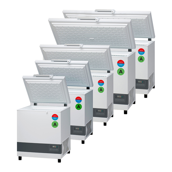
- Página 4 VLS204 to 404A AC .........29 PQS Code Model PQS Performance PQS Independent specifications type-testing protocol Specification reference: Product verification protocol: E003/109 VLS 204A AC E003/RF03.4 E003/RF03-VP.3 E003/110 VLS 304A AC E003/RF03.4 E003/RF03-VP.3 E003/111 VLS 354A AC E003/RF03.4 E003/RF03-VP.3 E003/112 VLS 404A AC E003/RF03.4 E003/RF03-VP.3...
- Página 5 Periodic preventive maintenance checks Daily Check: Monitor Temperature. Lid fits and lock tight to cabinet Lid gasket not faulty. Weekly maintenance: Remove any water at the bottom of the refrigerator with a cloth. Wipe of water droplets on the inside wall. Monthly maintenance: Clean grille for compressor compartment.
- Página 6 VLS 204A AC Complete spare part list VLS204A AC Position Item number Item name 0061 0-6538001 Filter drier, 0070 A921001 Cover + wirring clamp 0087 0-6038175 Base plate fittings, complete 0129 8-036038297 Compressor - TLES7KTK , Complete, 0153 7535254 Power cord EU H05VV-F 3G1 C13 jack 90° blac...
- Página 8 VLS 304A AC Complete spare part list VLS304A AC Position Item number Item name 0061 0-6538001 Filter drier, 0070 A921001 Cover + wirring clamp 0087 0-6038175 Base plate fittings, complete 0129 8-036038297 Compressor - TLES7KTK , Complete, 0153 7535254 Power cord EU H05VV-F 3G1 C13 jack 90° blac 5000 3010049 Drain plug...
- Página 10 VLS 354A AC Complete spare part list VLS354A AC Position Item number Item name 0061 0-6538001 Filter drier, 0070 A921001 Cover + wirring clamp 0087 0-6038175 Base plate fittings, complete 0129 8-036038255 Compressor - NLE 9KTK , Complete, R600a 0153 7535254 Power cord EU H05VV-F 3G1 C13 jack 90°...
- Página 12 VLS 404A AC Complete spare part list VLS404A AC Position Item number Item name 0061 0-6538001 Filter drier, 0070 A921001 Cover + wirring clamp 0087 0-6038175 Base plate fittings, complete 0129 8-036038255 Compressor - NLE 9KTK , Complete, R600a 0153 7535254 Power cord EU H05VV-F 3G1 C13 jack 90°...
- Página 14 VLS 504A AC Complete spare part list VLS504A AC Position Item number Item name 0061 0-6538001 Filter drier, 0087 0-6038175 Base plate fittings, complete 0129 8-03606510309 Compressor - HXK12AT , Complete, 0153 7535254 Power cord EU H05VV-F 3G1 C13 jack 90° black 2 0550 6520510 Run cap.
- Página 16 Vital components Position Item no Description VLS204A AC & VLS304A AC: 0129 8-036038297 Compressor VLS354A AC & VLS404A AC: 0129 8-036038255 Compressor VLS504A AC 0129 8-03606510309 Compressor 5713 7020961 Sensor 5712 7095514 Thermostat VLS204,304,354,404A AC 5851 6520229 Run capacitor VLS504A AC 0550 6520510 Run capacitor...
- Página 17 Health and safety guidance – Warning! Before any repair job be aware of following! WARNING: Before servicing or cleaning the appliance, disconnect it from power source. WARNING: Danger risk of fire or explosion. Flammable refrigerant used. To be repaired only by trained personnel.
- Página 18 Required basic tools 1. Flexible socket wrench 2 Socket wrench - size 7mm 3. Nose plier 4. Phillips screwdriver 5. Torx screwdriver - size t10+t20 6. Screwdriver - size 1,0x6,0 7. Screwdriver – size 0,6x3,5 8. Multimeter Proposed additional service kit/items Sealing kit Tar tape Extra self-tapping screws...
- Página 19 Wire diagram VLS204A AC / 304A AC...
- Página 20 Wire diagram VLS354A AC / 404A AC...
- Página 21 Wire diagram VLS504A AC...
- Página 22 Motor compartment How to get access to the motor compartment. 1. Use a screwdriver to unlock all 7 clamps. 2. Unlock all 7 clamps 3.Gently pull the compressor grille.
- Página 23 Thermostat replacement The thermostat is in the junction box lo- Frotal con pantallaFront with Display cated on the rear of the appliance Side view. Back with 3x sensor-wire sockets 1: Open the junction box by unscreewing 2: Remove grounding cable from junction the 6 Torx 20 screws and unmount lid box by unscrewing bolt with a wrench 6mm...
- Página 24 3: Remove 2 clamps from thermostat Fixing clamp 5: Use your finger to press and slide the 4: Use your finger to press and slide the lower clamp backwards to remove from the lower clamp backwards to remove from the thermostat body thermostat body 6: Push the thermostat out...
- Página 25 8: Switch the 3 power the wires from old to 9: Put the thermostat back in place new thermostat one by one 10: Use your finger to press and slide the 11: Use your finger to press and slide the upper clamp back in place to secure fixture upper clamp back in place to secure fixture of the thermostat...
- Página 26 Thermostat adjustment The thermostat is default factory set, and as a general rule not supposed to be adjusted. In the event, it is assessed by a cold chain technician that a thermostat adjustment is required, follow this instruction. Steps: 1. Press < > ”up/down” and hold 5 seconds to access the menu.
- Página 27 Thermostat sensor replacement The thermostat sensor is placed inside the 1: Dismount the sensor cover by loosen the compartment of the appliance. 2 x torx screws – size 10. Tar kit 2. Remove the wire sealing and the 3. Remove black sealing tar-kit and gently sensor from the cover.
- Página 28 Thermostat sensor Tape Thermometer sensor Tar kit 7. IMPORTANT! When re-mounting the new 6. When re-mounting the new thermostat thermostat sensor remember to properly senor, use removable tape. seal the wire feed through. 8. IMPORTANT! When re-mounting the new thermometer make sure the wire sealing plug is placed properly.
- Página 29 Starting device replacement for VLS204 to 404A AC Back with connection plug. Front with terminals. Side view. The starting device is mounted on the left side of the compressor.
- Página 30 2. Push the plastic cover up. 1. Dismount the cover for starting device by loosen the phillips screw. 4. Use a screw driver and gently remowe 3. Pull the cover back to loosen. the starter from the socket of compressor. 6.
- Página 31 8. Use a nose plier to unmount the wire 7. Push the plastic bracket up. sockets from starting device. 9. Exchange the wires 1/1 from the old starting device to the new one.
- Página 32 Starting device replacement for VLS504A AC Right side view Front with terminals. Left side view. The starting device is mounted on the left side of the compressor.
- Página 33 1. Dismount the cover by pushing the cover The starting device is placed in the left side lock from right to the left with a flat screw of the compressor compartment, fixed to driver. the compressor bracket. 3. Use a screw driver to losen 3 x screws. 2.
- Página 34 6. Exchange the wires 1/1 from the old starting device to the new one.
- Página 35 Run capacitor replacement VLS204 to 404A AC 1. Remove nuts to unmount assembly plate The run capasitor is placed in the left side for run capacitor. Lift up and pull out the of the compressor compartment, fixed to assembly plate. the terminal bracket.
- Página 36 Run capacitor replacement for VLS504A AC 1. Dismount the cover by pushing the cover The run capasitor is placed in the left side lock from right to the left with a flat screw of the compressor compartment, fixed to driver. the compressor bracket.
- Página 37 Thermometer replacement The thermometer is placed in at the front of Thermometer display. the appliance. The thermometer sensor is placed inside 1: Dismount the temperature sensor cover the compartment of the appliance. by loosen the 2 x torx screws – size 10. Tar kit 3.
- Página 38 5. Use a screw driver to gently push the 4. Gently pull the white wire until the probe socket of the thermometer. is visible. 6. Temperature monitor is loose from 7. Thermometer comes with wire and cabinet. sensor. 8. Installation of thermometer display. 9.
- Página 39 Thermostat sensor Tape Thermometer sensor 11. When re-mounting the new thermome- 10. Thermometer display is in place. ter senor, use removable tape. Tar kit 13. IMPORTANT! When re-mounting the 12. IMPORTANT! When re-mounting the new thermometer make sure the wire new thermometer remember to properly sealing plug is placed properly.
- Página 40 Fan replacement VLS504A AC The fan is placed at the left side of the compressor. 1. Dismount the fan from the bracket by 2. Remove strips for free access to the fan. losen the 2 hexagon bolts with a Socket When mounting the fan please remem- wrench.
- Página 41 Compressor replacement Procedure of compressor switch. 1: WARNING! Drain coolant R600a from refrigeration system by vacuum suction. 2: IMPORTANT! Blow refrigeration system with NO/Nitrogen 3: Cut A: Suction and pressure tube B: Capillary tube C: Dry filter 4: Dismount starting device 5: Dismount old compressor 6: Insert new compressor 7: Solder...
- Página 42 On-site checklist ● Is the green diode in the control panel on (Power check)? ● Temperature records (manual records, FT2 data) ● Is the internal temperature inside the acceptable range of +2° to +8°? ● Is the vaccine compartment clean and without condensation (water)? ●...
- Página 43 Trouble shooting Fault Possible cause Remedy Compressor is Be patient, it is most likely that the If this is not the case, check the not running. compressor will start within a few following: minutes. Power for appliance is not plugged in Check that the power for appliance is plugged in Check that the power for stabilizer...
- Página 44 Technical support When contacting Vestfrost Solutions technical support please supply below information: 1. Model 2. Serial number 3. What is the issue Rating plate Model Serial no. Contact: Vestfrost Solutions Tel. +45 75142250 cce-service@vestfrostsolutions.com Or visit our service-center webpage: http://www.vestfrostsolutions.com/service-center/...
- Página 45 Recycling procedures Information for Users on Collection and Disposal Old Equipment and used Batteries This symbol on the products, packaging, and/or accompanying documents mean that used electrical and electronic products and batteries should not be mixed with general household waste. For proper treatment, recovery and recycling of old products and used batteries, please take them to applicable collection points, in accordance with your national legislation and the Directives 2012/19/EU and 2006/66/EC.
- Página 46 ADVERTENCIA ADVERTENCIA: Puesto que el aparato contiene un refrigerante de hidrocarburos, No utilice aparatos eléctricos por favor, consulte la lista de dentro del compartimento de al- directrices que figura más abajo macenamiento de alimentos del aparato, a menos que sean del La cantidad y el tipo de refrige- tipo recomendado por el fabri- rante usado en su aparato se...
- Página 47 ADVERTENCIA: ADVERTENCIA: La limpieza y el mantenimiento no ubique las tomas de corriente rutinario no deben encomendar- portátiles o suministros de ener- se a los niños a menos que sean gía portátiles en la parte trasera mayores de 8 años y lo hagan del aparato.
- Página 48 Codigo PQS Modelo Especificaciones de Protocolo independiente de prueba rendimiento de PQS de PQS Referencia de especificación: Protocolo de verificación de producto: E003/109 VLS 204A AC E003/RF03.4 E003/RF03-VP.3 E003/110 VLS 304A AC E003/RF03.4 E003/RF03-VP.3 E003/111 VLS 354A AC E003/RF03.4 E003/RF03-VP.3 E003/112 VLS 404A AC E003/RF03.4...
- Página 49 Comprobaciones periódicas de mantenimiento preventivo Comprobación diaria: Vigile la temperatura. La tapa encaja bien y cierra herméticamen- te el cofre La junta de la tapa no está defectuosa. Mantenimiento semanal: Retire el agua que pueda haber en el fondo del refrigerador con un paño. Limpie las gotas de agua en la pared interior.
- Página 50 VLS 204A AC Recambios VLS204A AC Posición Código de artículo Nombre del artículo 0061 0-6538001 Filtro secadero 0070 A921001 Cubierta + sujetador de cable 0087 0-6038175 Placa base accesoria, complete 0129 8-036038297 Compressor - TLES7KTK , Completa, 0153 7535254 Linea de conexión...
- Página 52 VLS 304A AC Recambios VLS304A AC Posición Código de artículo Nombre del artículo 0061 0-6538001 Filtro secadero 0070 A921001 Cubierta + sujetador de cable 0087 0-6038175 Placa base accesoria, complete 0129 8-036038297 Compressor - TLES7KTK , Completa, 0153 7535254 Linea de conexión 5000 3010049 Salida de agua de deshielo...
- Página 54 VLS 354A AC Recambios VLS354A AC Posición Código de artículo Nombre del artículo 0061 0-6538001 Filtro secadero 0070 A921001 Cubierta + sujetador de cable 0087 0-6038175 Placa base accesoria, complete 0129 8-036038255 Compressor - NLE 9KTK , Completa, R600a 0153 7535254 Linea de conexión 5000...
- Página 56 VLS 404A AC Recambios VLS404A AC Posición Código de artículo Nombre del artículo 0061 0-6538001 Filtro secadero 0070 A921001 Cubierta + sujetador de cable 0087 0-6038175 Placa base accesoria, complete 0129 8-036038255 Compressor - NLE 9KTK , Completa, R600a 0153 7535254 Linea de conexión 5000...
- Página 58 VLS 504A AC Recambios VLS504A AC Posición Código de artículo Nombre del artículo 0061 0-6538001 Filtro secadero 0087 0-6038175 Placa base accesoria, complete 0129 8-03606510309 Compressor - HXK12AT , Completa, 0153 7535254 Linea de conexión 0550 6520510 Condensador de servicio-4µF 1126 0-A921012 Cubierta + sujetador de cable...
- Página 60 Componentes vitales Posición N.º artículo Descripción VLS204A AC & VLS304A AC: 0129 8-036038297 Compresor VLS354A AC & VLS404A AC: 0129 8-036038255 Compresor VLS504A AC: 0129 8-03606510309 Compresor 5713 7020961 Sensor 5712 7095514 Termostato VLS204,304,354,404A AC 5851 6520229 Capacitor de marcha VLS504A AC 0550 6520510...
- Página 61 Guía de salud y seguridad – ¡Advertencia! Tenga en cuenta lo siguiente antes de cual- quier trabajo de reparación. ADVERTENCIA: Antes de efectuar el mantenimiento o la limpieza del aparato, desconéctelo de la alimentación eléctrica. ADVERTENCIA: Peligro de incendio o explosión. Se usa refrigerante inflamable.
- Página 62 Herramientas básicas necesarias 1. Llave inglesa flexible 2 Llave inglesa - calibre 7mm 3. Alicates de punta 4. Destornillador Phillips 5. Destornillador Torx - calibre t10+t20 6. Destornillador - calibre 1,0x6,0 7. Destornillador - calibre 6,0x3,5 8. Multímetro Kit de servicio/artículos adicionales propu- estos Kit de sellado Cinta de alquitrán...
- Página 63 Diagrama electrico VLS204A AC / 304A AC...
- Página 64 Diagrama electrico VLS354A AC / 404A AC...
- Página 65 Diagrama electrico VLS504A AC...
- Página 66 Compartimento del motor Cómo acceder al compartimento del motor. Utilice un destornillador para desmontar la rejilla.. Desbloquee las 7 sujeciones y tire de la parri- lla del compresor hacia abajo.
- Página 67 Reemplazo del termostato El termostato se encuentra en la caja de Frotal con pantalla conexiones situada en la parte trasera del aparato Parte posterior con 3x tomas de cable Vista lateral sensor 1: Abra la caja de conexiones desatornil- 2: Retire el cable de conexión a tierra, de lando los 6 tornillos Torx 20 y desmonte la la caja de conexiones, desatornillando el tapa...
- Página 68 3: Retire las 2 abrazaderas del termostato Abrazadera de fijación 5: Utilice el dedo para presionar y deslizar 4: Utilice el dedo para presionar y deslizar la abrazadera inferior hacia atrás para la abrazadera superior hacia atrás para retirarla del cuerpo del termostato retirarla del cuerpo del termostato 6: Saque el termostato 7: Cambie el enchufe del cable del sensor,...
- Página 69 8: Cambie los 3 cables de alimentación, del 9: Vuelva a colocar el termostato en su viejo, al nuevo termostato, uno por uno lugar 10: Utilice el dedo para presionar y deslizar 11: Utilice el dedo para presionar y deslizar la abrazadera superior hacia atrás, para la abrazadera inferior hacia atrás, para asegurar el montaje del termostato...
- Página 70 Ajuste del termostato El termostato está ajustado de fábrica pre- determinado, y como regla general, no se supone que se debe ajustar. En el caso de que un técnico de cadena de frío evalúa que se requiere un ajuste del termostato, siga estas instrucciones.
- Página 71 Sustitución del sensor de termostato El sensor de termostato está ubicado den- 1: Desmonte la cubierta del sensor aflo- tro del compartimento del aparato. jando los 2 tornillos torx - calibre 10. Kit de al- quitrán 2. Retire la junta de cable y el sensor 3.
- Página 72 Sensor de termostato Cinta Sensor de termómetro Kit de alquitrán 7. ¡IMPORTANTE! Al montar el nuevo 6. Al volver a montar el sensor de termo- sensor de termostato, recuerde sellar stato nuevo, utilice cinta removible. correctamente el pasamuros de cable. 8.
- Página 73 Sustitución del dispositivo de arranque VLS204 para 404A AC Parte trasera con clavija de conexión. Frontal con terminales. Vista lateral. El dispositivo de arranque se monta en el lado izquierdo del compresor.
- Página 74 2. Levante la cubierta de plástico. 1. Desmonte la cubierta del dispositivo de arranque aflojando el tornillo Phillips. 4. Utilice un destornillador y retire cuida- 3. Tire de la tapa hacia atrás para aflojarla. dosamente el arrancador de la toma del compresor.
- Página 75 8. Use unos alicates de punta para extraer 7. Levante el soporte de plástico. los conectores de cable del dispositivo de arranque. 9. Cambie los cables 1/1 del dispositivo de arranque antiguo al nuevo.
- Página 76 Sustitución del dispositivo de arranque VLS504A AC Vista del lado derecho. Frontal con terminales. Vista del lado izquierdo. El dispositivo de arranque se monta en el lado izquierdo del compresor.
- Página 77 Dispositivo de arranque está situado en la 1. Desmonte la cubierta empujando el parte izquierda del compartimento del com- cierre de la cubierta de derecha a izqui- presor, fijado en el soporte del compresor. erda con un destornillador plano. 3. Utilice un destornillador para aflojar 3x 2.
- Página 78 6. Cambie los cables 1/1 del dispositivo de arranque antiguo al nuevo.
- Página 79 Sustitución del capacitor de marcha VLS204 para 404A AC 1. Extraiga las tuercas para desmontar las placas El capacitor de marcha está situado en la de ensamblaje para el capacitor de marcha. parte izquierda del compartimento del com- Levante y extraiga la placa de ensamblaje. presor, fijado en la regleta de terminales.
- Página 80 Sustitución del capacitor de marcha VLS504A AC 1. Desmonte la cubierta empujando el El capacitor de marcha está situado en la cierre de la cubierta de derecha a izqui- parte izquierda del compartimento del com- erda con un destornillador plano. presor, fijado en el soporte del compresor.
- Página 81 Sustitución del termómetro El termómetro está ubicado en la parte Pantalla del termómetro. frontal del aparato. El sensor de termómetro está ubicado den- 1: Desmonte la cubierta del sensor de tro del compartimento del aparato. temperatura aflojando los 2 tornillos torx - calibre 10.
- Página 82 5. Utilice un destornillador para empujar 4. Tire suavemente del cable blanco hasta cuidadosamente el conector del termó- que sea visible la sonda. metro. 6. El monitor de temperatura está 7. El termómetro incluye cable y separado del cofre. sensor. 8.
- Página 83 Sensor de termostato Cinta Sensor de termómetro 11. Al volver a montar el sensor de termó- 10. La pantalla del termómetro está en su metro nuevo, utilice cinta removible. sitio. Kit de alquitrán 13. ¡IMPORTANTE! Al montar el nuevo 12. ¡IMPORTANTE! Al montar el nuevo ter- termómetro asegúrese de que el tapón mómetro, recuerde sellar correctamente de sellado de cable esté...
- Página 84 Sustitución del ventilador VLS504A AC El dispositivo de arranque está montado en la parte izquierda del compresor. 1. Desmonte el ventilador de la sujeción 2. Retire las tiras para acceder libremente aflojando los 2 tornillos hexagonales con al ventilador. Al montar el ventilador, una llave inglesa.
- Página 85 Sustitución del compresor Procedimiento del interruptor del compre- sor. 1: ¡ADVERTENCIA! Drene el refrigerante R600a del sistema de refrigeración medi- ante succión por vacío. 2: ¡IMPORTANTE! Insufle en el sistema de refrigeración NO/nitrógeno 3: Corte A: Succión y manguera de presión B: Tubo capilar C: Filtro seco 4: Desmontar dispositivo de arranque...
- Página 86 Lista de verificación in situ ● ¿Está el diodo verde del panel de control encendido (comprobación de alimentación)? ● Registros de temperatura (registros manuales, datos FT2) ● ¿Está la temperatura dentro del rango aceptable de +2° a +8°? ● ¿Está el compartimento de vacunas limpio y sin condensación (agua)? ●...
- Página 87 Corrección de fallos Fallo Causa posible Solución El compresor no está Espere, lo más probable es que el Si esto no sucediera, compruebe lo en funcionamiento, y compresor vuelva a funcionar a los pocos siguiente: los paquetes de hielo minutos. no están fríos La alimentación del aparato no está...
- Página 88 Asistencia técnica Cuando contacte con el servicio técnico de Vestfrost Solutions, le rogamos proporcione la información siguiente: 1. Modelo 2. Número de serie 3. Descripción del problema Placa de características Modelo N.º de serie Contacto: Vestfrost Solutions Tel. +45 75142250 cce-service@vestfrostsolutions.com...
- Página 89 Eliminación de electrodomésticos Información para Usuarios sobre la Recolección y Eliminación de apara- tos viejos y baterías usadas. Estos símbolos en los productos, embalajes y/o documentos adjuntos, sig- nifican que los aparatos eléctricos y electrónicos y las baterías no deberían ser mezclados con los desechos domésticos.Para el tratamiento apropiado, la recuperación y el reciclado de aparatos viejos y baterías usadas, por favor, observe las normas de recolección aplicables, de acuerdo a su legislación...
- Página 92 8195 070 Rev 07...