
Manuales relacionados para GUTMANN Rayo


Resumen de contenidos para GUTMANN Rayo
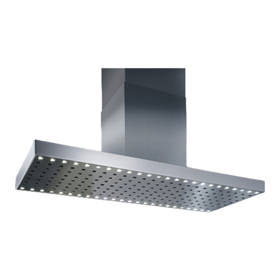
- Página 1 Rayo Montageanleitung Installation instructions Notice de montage Istruzioni per il montaggio Instrucciones de montaje...
-
Página 2: Sicherheitshinweise
a n g e s c h l o s s e n w e r d e n . A l s Sicherheitshinweise Trennvorrichtung gelten Schalter mit einer Kontaktöffnung von mindestens 3 Montage, Anschluss, Inbetriebnahme mm und allpoligen Schaltern, z.B. LS- und Reparatur dürfen nur von einer Schalter und Schütze. - Página 3 Mindestabstand zum Kochstelle Montageanleitung Die optimale Ansaugleistung erreichen Wandhaube Sie, wenn die Haube in einer Höhe von 750mm ab Oberkante Arbeitsplatte montiert wird. Vorschrift bei Gas sind 650mm. Um Kondensatbildung zu verhindern, muss eine Rückstauklappe direkt am Luftaustritt außen montiert werden.
- Página 4 3. Löcher bohren und entsprechende Dübel bündig einsetzen. 4. Aufhängung (Turmhaltewinkel A) des Oberturms befestigen. 5. Stockschrauben soweit in die Dübel 2 Löcher (Ø6mm) für die Aufhängung (Ø10 mm) einschrauben, dass noch ca. des Oberturms 20 mm hervorstehen. 2 Löcher (Ø10mm) für die Befestigung der Dunstabzugshaube 6.
- Página 5 10. Den elektrischen Anschluss herstel- len. (Abluftbetrieb) Beim Einsatz eines externen Gebläsemotors Anschlusska- bel verbinden. 13. Unterturm ein wenig nach außen weiten und über den Oberturm und das Modul der Dunstabzugshaube aufset- zen. Der Unterturm muss auf der Haube ruhen. 11.
- Página 6 3. Um eine optimale Abzugskapazität zu A: Schnellmontageflansch erreichen, Position der Dunstabzugs- B: Oberturm haube mittig über der Kochstelle festle- gen (ein Lot zur Hilfe nehmen) und den C: Unterturm Mittelpunkt des Turmes an der Decke D: elektrische Zuleitung markieren. E: Anschlußstutzen F: Verschraubungspunkte G: Haubenkörper mit Lüftermodul...
- Página 7 9. Unterturm über den Oberturm schie- ben und mit Klebeband fixieren. 10. Abluftschlauch an der Dunstabzugs- haube befestigen, auf Knickfreiheit ach- ten. Den elektrischen Anschluß herstel- len. (Abluftbetrieb) Beim Einsatz eines externen Gebläsemotors Anschlusska- bel verbinden. 11. Maß (X-Y) ermitteln, X = Abstand Kochfläche zur Decke, Y = Abstand Kochfläche zur Haube.
- Página 8 12. Dunstabzugshaube anheben und in 15. Funktionstest durchführen den Oberturm schieben, so dass die vorgefertigten Langlöcher mit den Be- Montage einteiliger festigungslöchern am Modul überein- stimmen. Turm 13. Dunstabzugshaube am Oberturm 1. Kunststoff - Blindstopfen am Modul befestigen (mitgelieferte M5 Schrauben entfernen (4 Stück) verwenden).
- Página 9 Hinweis: - Bei Umlufthauben und Einsatz von C a r b o n f i l t e r n s e p . B e d i e u n g s - Installationsanleitung beachten. - Bei Sommer-Winter bzw. VSA - Schal- tung: sep.
- Página 10 Umwelthinweise Verpackung Die Verpackung des Geräts ist recyclebar. Als Verpackungsmaterial werden Karton und Polyethylenfolie (PE) verwendet. Diese Materialien sind auf umweltge- rechte und den jeweiligen vor Ort gel- tenden Vorschriften entsprechende Wei- se zu entsorgen. Umwelthinweise Dieses Gerät ist entsprechend der euro- päischen Richtlinie 2002/96/EG über Elektro- und Elektronikaltgeräte (waste electrical and electronic equip-...
- Página 11 Risk of electric shock Important Information The mains voltage must correspond with the specifications on the rating plate. General The rating plate is situated near the These Installation instructions contain filters inside the hood. Connect the ex- important Information which must be tractor hood to a correctly installed observed in order that the extractor earthed socket only.
- Página 12 plates/ hobs is min. 650 mm. Installation instructions Minimum distance from a gas cook- ing appliance for wall-mount hood Minimum distance between the lower edge of the extractor hood and hot- plates/ hobs is. min. 750 mm. If the manufacturer of the gas cooking appli- ance specifies a greater distance, this must be taken into consideration.
- Página 13 3. Drill the holes and insert the corre- sponding wall plugs flush with the wall: 4. Attach the bracket for the upper tower. 5. Screw woodtometal dowel screws into the wall plugs (10 mm holes), leav- 2. Mark the positions for the following ing them projecting by 20 mm.
- Página 14 9. (Exhaust-air mode) attach and secure 13. lnsert the upper tower into the reten- the exhaust-air hose, ensuring that the tion plate on the tower bracket until the hose is not kinked. upper tower locks into Position. 10. Connect the power supply. (Exhaust -air mode) if using an external fan mo- tor, attach the connection cable.
- Página 15 2. Determine the control side of the Installation instructions hood; the control panel is on this side. for Island hood 3. To obtain Optimum extraction capac- ity, centre the extractor hood over the hotplate (use a plumb) and mark the centre point of the tower on the ceiling.
- Página 16 8. Slip the upper tower over the exhaust air hose + electrical connecting cable. Then fasten the upper tower to the ceil- ing using washers and nuts, or using a quick assembly flange. (Special tool type 1000, .55999800). 7. Then guide the exhaust air hose (extraction mode) and the connect- ing cable down from the ceiling.
- Página 17 14. By removing the adhesive tape, loosen the lower tower and pull down until it is positioned on the hood. 15. Carry out a functional test! Single-piece tower unit 12. Lift up the extractor hood and push it into the upper tower, so that the pre- 1.
-
Página 18: Environmental Information
4. Push the tube from below into the motor module until the metal clip on the inside of the cover is positioned to contact the motor module (4 x). 5. Screw the metal clips with the tube from above to the cover of the motor module (4 x). -
Página 19: Consignes De Sécurité
Avant de percer les fixations, assurez- Consignes de sécurité vous qu’aucun câble électrique ne soit endommagé. Réalisez le branchement Seul un personnel qualifié est autorisé à électrique de telle manière à pouvoir procéder au montage, aux branche- raccorder facilement la hotte. Respectez ments, à... - Página 20 electriques et l’arete inferieure de la Notice de montage de la hotte aspirante: 650 mm. Appareils de cuisson au gaz Veuillez respecter les hotte murale prescriptims et consignes de montage appiicables, publiees par les fabricants de ces appareils. Le montage de la hot- te aspirante ä...
- Página 21 3. Percez les trous, puis enfoncez les chevilles a ras de la surface : 4. Fixez la Suspension du conduit supe- rieur. 5. Vissez les vis sans tete dans les che- villes (trous de 10 mm) jusqu’ä ce qu’el- 2. A l’aide des dimensions donnees, les ne depassent plus que de 20 mm.
- Página 22 9. lnstallez et fixez le flexible a air vicie (evacuation de l’air a l’exterieur); veillez a ce qu’il ne presente pas de pli. 12. lntroduisez le conduit superieur dans les pattes de fixation de la Suspension de conduit, jusqu’ä ce que ce dernier encrante.
- Página 23 2. Determinez le cöte de commande de Notice de montage de la la hotte ; le bandeau de commande se trouvera sur ce cöte. hotte Tlot 3. Pour obtenir une capacite d’aspiration optimale, centrez la hotte au-dessus du foyer (servezvous d’un fil a plomb), puis marquez au plafond le mälieu du condu- A : bride de montage rapide B : tour haute...
- Página 24 5. Visser les vis double filet dans les Glisser la tour haute par dessus chevilles en en laissant dépasser 20 flexible d’évacuation et le raccordement En cas de tours standard à bride électrique, la fixer ensuite avec la pla- de montage rapide, visser immédiate- que d’appui et les écrous, resp.
- Página 25 15. Dans le cas d’une version à circula- tion : Fixer la pièce de renvoi avec les 12. Relever la hotte aspirante et la glis- tôles de maintien et la grille de soufflerie ser dans la tour haute, de sorte que les à...
- Página 26 Montage tour monobloc - 17.) Retirer le capuchon en plastique sur le module (4 pcs.) 18.) Dévisser la vis à tôle sur le module (4 pcs.) 19.) Glisser les clips métalliques dans le tuyau et les engager dans la rainure, le cas échéant avec un maillet (4 pcs.) 21.) Visser les clips métalliques depuis le haut au couvercle du module mo-...
-
Página 27: Respect De L'eNvironnement
X= M8 Stockschraube + Dübel für Respect de l’environnement Turmaufhängung M8=Gewindestange für Haubenaufhän- Cet appareil est marque selon la gungen directive europeenne 2002/96/ EG relative aux appareils electri- ques e! ölectroniques usages (waste electrical and electronic equipment - WEEE). La directive delinit ie cadre pour une reprise et une recuperation des appareils usages appiicables dans les pays de la CE. -
Página 28: Per La Vostra Sicurezza
cedere alla perforazione dei muri per Per la vostra sicurezza creare i buchi di fissaggio, accertarsi che nessuna linea elettrica possa esse- Il montaggio, l’allacciamento alla rete, la re danneggiata durante l’operazione. messa in funzione e le riparazioni devo- L’allacciamento alla rete elettrica deve no essere effettuate solamente da per- consentire un facile collegamento della sonale autorizzato, che ha il compito di... - Página 29 produttore degü apparecchi a gas. So- Istruzioni per il montaggio pra a fomelli a gas l’installazione della cappa aspirante e consentita con una della cappa aspirante murale distanza minima di 750 mm. solo se non si superano i seguenti carichi termici nominali: Cucine a gas Carico termico di un for...
- Página 30 2. Stabilire le posizioni dei seguenti fori di fissaggio con l’aiuto delle dimensioni indicate. Le misure mancanti dipendono dal modello e devono essere misurate sulla cappa aspirante. Fare attenzione a rispettare la distanza minima fra fornelli e bordo inferiore della cappa aspirante. 3.
- Página 31 10. Eseguire l’allacciamento elettrico. 12. lnserire la torre superiore nella lin- (Funzionamento ad espulsione d’aria) In guetta di sostegno della sospensione caso d’impiego di un motore della vento- della torre, finche non s’innesta. la esterno, collegare il cavo. 13. Allargare un poco la torre inferiore ed inserirla sulla torre superiore e sul 11.
- Página 32 1. (Per funzionamento ad espulsione d’aria) predisporre un idoneo scarico nel muro o nel soffitto. Creare le condizioni per il montaggio della cappa nel luogo di installazione, coprire gli utensili da cuci- na, ecc. 4. Stabilire le posizioni dei fori di fissag- gio con l’aiuto della sagoma.
- Página 33 11. Prendere le misure (X-Y), X = di- stanza piano di cottura dal soffitto, Y = distanza piano di cottura dalla cappa. 8. Far scorrere la colonna superiore sopra il condotto di uscita per aria di scarico e sui cavi di allacciamento elet- trico, dopodiché...
- Página 34 Montaggio colonna monopezzo 1 Rimuovere i tappi filettati di plastica dal modulo (4 pezzi) 14. Liberare la colonna inferiore rimuo- vendo il nastro adesivo e tirarla verso il basso, fino a che si sia posizionata sulla cappa. 2 Estrarre le viti per lamiera dal modulo (4 pezzi).
-
Página 35: Smaltimento
4. Avvitare dall’alto le clip di metallo e il tubo al coperchio del modulo motore ( 4 x ). Smaltimento 5. Inserire ora le barre filettate nel tubo. A questo punto è possibile montare la Imballaggio cappa con le barre filettate. L’imballaggio è... - Página 36 Para el montaje seguro de la campana Instrucciones de montaje extractora sobre bases de sustentaciön m e n o r e s t a b i l i d a d d e b e r a para todos Los grupos consultarse a un especialista en Advertencia importancia construcciön, como por ejemplo un...
- Página 37 al respecto. Conducciön del aire de Gas cookers evacua-ciön al exterior La evacuaciön Load of one hotplate max. 3.0 kW del aire al exterior no debe realizarse a Load of all hotplates max. 8.3 kW traves de una chimenea que se utilice Load of the oven max.
-
Página 38: Funcionamiento De Extractor)
Practique dos taladros de 10 mm para fijar la campana extractora. 3. Practique los taladros en cuestiön e introduzca los tacos a ras con la pared. 4. Monte la sujeciön del mödulo de revestimiento superior. 5. Enrosque los tornillos de sujeciön de 2. - Página 39 Colocar y fijar la manguera del extactor, platina de sujeción de la suspensión del cuidar que no se formen dobleces. tubo hasta que encastre. 10. Lever a cabo la conexión eléctrica. 13. Extender el tubo inferior un poco (Funcionamiento de extractor) Conectar hacia fuera y poner encima del tubo el cable en caso de emplearse un motor superior y el módulo de la campana...
- Página 40 A: Brida de montaje rápido B: Torreta superior C: Torreta inferior D: Conductor de alimentación eléctrica E: Tubuladura de conexión F: Puntos de atornillamiento G:Cuerpo de campana con módulo de ventilador 1. (En caso de funcionamiento de extractor) Preparar un conducto de aire de salida apropiado en la pared / el techo.
- Página 41 11. Calcule la medida X-Y; X = distancia encimera a techo, Y = distancia encimera a campana. 8. Desplace la torreta superior sobre el tubo de evacuación y el cable de conexión eléctrica y fíjela al techo con arandelas y tuercas o con la brida de montaje rápido.
-
Página 42: Montaje De Torre De Una Pieza
Montaje de torre de una pieza 1. Retirar el tapón obturador de plástico en el módulo (4 unidades) Sacar el tornillo de chapa en el módulo (4 unidades) 14. Retire las tiras de cinta adhesiva de la torreta inferior y desplace ésta hacia abajo hasta situarla sobre la campana. -
Página 43: Eliminación Residuos
Eliminación residuos Embalaje El embalaje del aparato es reciclable. Para el embalaje se utiliza cartón y polietileno expandido. Estos materiales deben ser eliminados según la normativa vigente de protección del medio ambiente y las ordenanzas municipales correspondientes. Campana Su municipio le informará sobre la normativa de protección de medio ambiente para la correcta eliminación... -
Página 44: Veiligheidsinstructies
ontstaan. Draag werkhandschoenen Veiligheidsinstructies tijdens de montage. Algemeen Gevaar door een elektrische schok Deze montagehandleiding bevat De netspanning moet overeenkomen belangrijke aanwijzingen die in acht met de gegevens op het typeplaatje. Het moeten worden genomen zodat de typeplaatje bevindt zieh bij de filters aan afzuigkap zonder gevaar en storingsvrij de binnenzijde van de kap. - Página 45 acht.Het luchtafvoer-kanaal en de Montagehandleiding afzuigkap elektrische aansluiting moeten zödanig worden voorbereid dat de afzuig-kap met muurbevestiging daarmee eenvoudig kan worden verbunden. De luchtafvoerslang mag niet geknikt zijn. Fomuis voor vaste brandstoffen Boven fornuis voor vaste brandstoffen waarvan brandgevaar kan uitgaan (bijv.
- Página 46 3. Boor de gaten duw de pluggen tot aan de rand in de gaten. 4. Ophanging van de boventoren bevestigen. 5. Schroef de schroeven zo ver in de pluggen (10 mm gaten) dat de 2. Bepaal de posities van de volgende schroeven nog 20 mm uitsteken.
- Página 47 10. Breng de elektrische aansluiting tot 12. Buig de ondertoren iets open en stand (gebruik met afvoerlucht). Sluit de plaats hem over de boventoren en de aansluitkabel aan Indien een externe afzuigkap. De ondertoren moet op de ventilatormotor wordt gebruikt. afzuigkap rüsten.
- Página 48 A: Snelmontageflens worden vastgelegd (gebruik een B: Boventoren schietlood); markeer het middelpunt van C: Ondertoren de toren op het plafond. D: Elektrische toevoerleiding E: Aansluitingsbuis F: Schroefverbindingspunten G: Kaplichaam ventilatormodule 1. (Bij gebruik met afvoerlucht) Bereid een geschikte luchtafvoeropening in het p l a f o n d v o o r .
- Página 49 9. De boventoren over de boventoren schuiven en met kleefband bevestigen. De elektrische aansluiting tot stand brengen (bedrijf met afgevoerde lucht). Wanneer een externe blazermotor gebruikt wordt, de aansluitingskabel verbinden. 10. (bedrijf met afgevoerde lucht) De slang voor de afgevoerde lucht aan de dampkap bevestigen, op knikvrijheid letten.
- Página 50 12. De dampkap opheffen en in de bevestigen. slang voor boventoren schuiven zodat de vooraf afgevoerde lucht tussen het ombuigstuk aangebrachte langsgaten met de en de module met behulp van de bevestigingsgaten op de module slangklem. overeenstemmen. 13. De dampkamp aan de boventoren Montage eendelige toren bevestigen (de meegeleverde M5 schroeven gebruiken).
-
Página 51: Afvoeren Van De Verpakking
Opmerking: - Bij circulatieluchtkappen en gebruik van Carbonf i l tern sep. de bedienings- installatieaanwijzingen naleven - Bij zomer-winter resp. VSA - schakeling: aparte handleiding volgen! Afvoeren van de verpakking verpakking apparaat kan worden gerecycled. Als verpakkingsmaterialen worden karton en polyethyleenfolie (PE) gebruikt. Deze materialen moeten worden afgevoerd op een voor het milieu verantwoorde wijze en volgens de plaat-selijk geldende... - Página 52 Exklusiv-Hauben GUTMAN GUTMAN GmbH GUTMAN GUTMAN Mühlacker Straße 77 D-75417 Mühlacker Deutschland info@gutmann-exklusiv.eu www.gutmann-exklusiv.eu HRB 705602 Amtsgericht Mannheim DE263391836 Index: 01 / 13 Artikel Nr.: 2331...