Tabla de contenido
Publicidad
Enlaces rápidos
ADVERTENCIA
Leer atentamente el manual antes de instalar y utilizar el dispositivo.
Este dispositivo debe ser instalado por personal cualificado conforme a
la normativa de instalación vigente a fin de evitar daños personales o
materiales.
● Antes de realizar cualquier operación en el dispositivo, desconectar la corriente de las
entradas de alimentación y medida.
● El fabricante no se responsabilizará de la seguridad eléctrica en caso de que el dispositivo no
se utilice de forma adecuada.
● Los productos descritos en este documento se pueden actualizar o modificar en cualquier
momento. Por consiguiente, las descripciones y los datos técnicos aquí contenidos no tienen
valor contractual.
● La instalación eléctrica del edificio debe disponer de un interruptor o disyuntor. Este debe
encontrarse cerca del dispositivo, en un lugar al que el usuario pueda acceder con facilidad.
Además, debe estar identificado como tal (IEC/ EN 61010-1 § 6.12.2.1).
● Limpiar el dispositivo con un trapo suave; no utilizar productos abrasivos, detergentes líquidos
o disolventes.
Índice
Smartphone
frontal
Doc: I414EGB09_14.doc
ATL600 - ATL610
CONMUTADOR AUTOMÁTICO DE RED
MANUAL DE INSTRUCCIONES
Página
2
2
3
3
3
4
4
5
5
7
8
8
8
9
9
9
10
10
11
11
11
12
13
20
20
20
21
21
22
23
24
25
30
30
30
32
E
ATL600 - ATL610
AUTOMATIC TRANSFER SWITCH CONTROLLER
INSTRUCTIONS MANUAL
WARNING!
Carefully read the manual before the installation or use.
This equipment is to be installed by qualified personnel, complying to
current standards, to avoid damages or safety hazards.
● Before any maintenance operation on the device, remove all the voltages from measuring and
supply inputs.
● Products illustrated herein are subject to alteration and changes without prior notice.
● Technical data and descriptions in the documentation are accurate, to the best of our
knowledge, but no liabilities for errors, omissions or contingencies arising there from are
accepted.
● A circuit breaker must be included in the electrical installation of the building. It must be
installed close by the equipment and within easy reach of the operator.
It must be marked as the disconnecting device of the equipment:
IEC /EN 61010-1 § 6.12.2.1.
● Clean the instrument with a soft dry cloth; do not use abrasives, liquid detergents or solvents
Index
26/09/2014
.
Page
2
2
3
3
3
4
4
5
5
7
8
8
8
9
9
9
10
10
11
11
11
12
13
20
20
20
21
21
22
23
24
25
30
30
30
32
p. 1 / 32
Publicidad
Tabla de contenido

Manuales relacionados para LOVATO ELECTRIC ATL600


Resumen de contenidos para LOVATO ELECTRIC ATL600
-
Página 1: Tabla De Contenido
ATL600 - ATL610 ATL600 - ATL610 CONMUTADOR AUTOMÁTICO DE RED AUTOMATIC TRANSFER SWITCH CONTROLLER MANUAL DE INSTRUCCIONES INSTRUCTIONS MANUAL ADVERTENCIA WARNING! Leer atentamente el manual antes de instalar y utilizar el dispositivo. Carefully read the manual before the installation or use. -
Página 2: Introducción
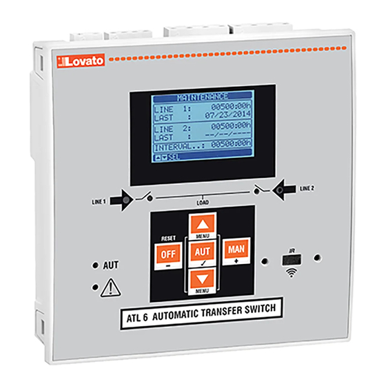
Introducción Introduction El diseño de las unidades de control ATL600 y ATL610 incorpora las The ATL600 and ATL610 control units have been designed to offer state- funciones más avanzadas para aplicaciones de supervisión y conmutación of-the-art functions for automatic transfer switching applications between automática entre dos líneas de alimentación trifásica. -
Página 3: Funciones De Las Teclas Frontales
1 está abierto o cerrado. El parpadeo between the desired state of the breaker and its true state detected by the indica que el estado previsto del ATL600 y el estado real detectado por la feedback input. -
Página 4: Puesta En Tensión
Puesta en tensión Power-up ATL600 tiene una alimentación de 100-240 V CA. ATL600 has 100-240VAC supply. ATL610 utiliza 100-240 V CA o 12-24 V CC. Cuando existen al mismo ATL610 has 100-240VAC or 12-24VDC supply. In the case of the tiempo ambas opciones, se concede prioridad a la corriente alterna. -
Página 5: Acceso Con Contraseña
Acceso con contraseña Password access La contraseña sirve para permitir o bloquear el acceso al menú de The password is used to enable or lock the access to setting menu configuración y al menú de comandos. (setup) and to commands menu. ... - Página 6 Estadísticas Statistics Line 2 MAN mode Line1 AUT mode Contador de Línea 1 Línea 2 Contador de commutation conmutación commutation conmutación counter en modo AUT counter en modo Contador de Time lapse Tiempo Alarm counter alarmas A03 with load transcurrido A03 A04 supplied con suministro...
-
Página 7: Capacidad De Expansión
Lista de eventos Event List Event code Código de evento Fecha y hora de Descripción evento Description de evento of event Nota: algunas de las páginas mencionadas arriba podrían no mostrarse si Note: Some of the pages listed above may not be displayed if the la función correspondiente no está... -
Página 8: Recursos Adicionales
En la siguiente tabla aparecen todas las variables internas que gestiona The following table groups all the I/O and the internal variables managed la unidad ATL600 y su rango correspondiente (número de variables por by the ATL600, with highlighting of their range (variables number per tipo). -
Página 9: Umbrales Límite (Limx)
Variables de control remoto (REMx) Remote-controlled variables (REMx) Las unidades ATL600 y ATL610 ofrecen la posibilidad de gestionar un ATL600 and ATL610 can manage up to 8 remote-controlled variables máximo de 8 variables por control remoto (REM1 a REM8). -
Página 10: Prueba Automática
La alarma puede generarse por varios motivos, como cuando se supera The condition that generates the alarm can be, for instance, the un umbral. En este caso, el origen será uno de los umbrales límite LIMx. overcoming of a threshold. In this case, the source will be one of the limit ... -
Página 11: Puerto De Programación Ir
Puerto de programación IR IR programming port Los parámetros de la unidad ATL6.. se pueden configurar por medio del The parameters of the ATL6.. can be configured through the front optical puerto óptico frontal mediante el uso de la llave de programación IR- port, using the IR-USB CX01 programming dongle or with the IR-WiFi USB con código CX01 o la llave IR-WiFi con código CX02. -
Página 12: Configuración De Parámetros (Setup) Mediante El Panel
Configuración de parámetros mediante el panel frontal Parameter setting (setup) from front panel Para acceder al menú de programación de parámetros: To open the parameters programming menu (setup): Poner la placa en modo OFF Turn the unit in OFF mode En la pantalla de medidas normal, pulsar ▲... -
Página 13: Tabla De Parámetros
Selected parameter New value entered Parámetro Nuevo valor seleccionado configurado Valor mínimo Valor máximo Minimum possible Maximum possible posible posible setting setting Valor Graph bar of the Barra gráfica valor- Factory default rango predeterminado value-range setting Configuración: página de edición Set-up: editing page ... - Página 14 P02.07 Tipo de control de tensión P02.07 Voltage control mode L-L + L-N L-L + L-N P02.08 Frecuencia nominal 50 HZ 50 HZ P02.08 Nominal frequency 50HZ 50 HZ 60 HZ 60 HZ P02.01: tensión nominal de la red y el generador. En sistemas multifásicos, configurar P02.01 –...
- Página 15 P05.22 Hora de rotación de generador 0...23 P05.22 Generator rotation hour 0...23 P05.23 Minutos de rotación de generador 0...59 P05.23 Generator rotation minutes 0...59 P05.01: define el tipo de aplicación para la gestión de uno o dos grupos electrógenos; activa P05.01 –...
- Página 16 M06 – CONTROL DE TENSIÓN DE LALÍNEA 1 Defecto Rango M06 – VOLTAGE CONTROL LINE 1 Default Range P06.01 Límite de tensión MÍN. desconexión 70-100 P06.01 MIN voltage limit for trip 70-100 P06.02 Umbral MÍN. restablecimiento 70-100 P06.02 MIN voltage pick-up 70-100 P06.03 Retardo de tensión MÍN.
- Página 17 P07.15 Límite de frecuencia MÍN. P07.15 MIN frequency limit 80-100 80-100 P07.16 Retardo de frecuencia MÍN. 0-600 P07.16 MIN frequency delay 0-600 P07.17 Control de LÍNEA 2 en modo P07.17 LINE 1 control OFF mode OFF/RESET OFF+GLOB OFF+GLOB ON+GLOB ON+GLOB P07.18 Control de LÍNEA 2 en modo MAN P07.18...
- Página 18 P09.01: activa la ejecución de la prueba periódica. Este parámetro se puede modificar P09.01 – Enable periodic test. This parameter can be changed directly on the front panel directamente desde el panel frontal sin acceder a la configuración (consultar el without using setup (see chapter Automatic Test) and its current state is shown on capítulo Prueba automática);...
- Página 19 P13.n.04 Función Máx. Máx. P13.04 Function Mín. Mín.+Máx. Min+Max P13.n.05 Umbral superior -9999 - +9999 P13.05 Upper threshold -9999 - +9999 P13.n.06 Multiplicador /100 – x10 k P13.06 Multiplier /100 – x10k P13.n.07 Retardo 0,0 – 600,0 P13.07 Delay 0.0 – 600.0 P13.n.08 Umbral inferior -9999 - +9999 P13.08...
-
Página 20: Alarmas
Alarmas Alarms Cuando se genera una alarma, en la pantalla aparece un icono de When an alarm is generated , the display will show an alarm icon, the alarma con el código de identificación y la descripción de la alarma en el code and the description of the alarm in the language selected. -
Página 21: Descripción De Las Alarmas
Descripción de las alarmas Alarm description CÓD. DESCRIPCIÓN CAUSA DE LA ALARMA DESCRIPTION ALARM EXPLANATION Tensión de la Tensión de la batería por debajo del umbral mínimo durante un Battery voltage too Battery voltage beyond the lowest threshold for a time batería demasiado tiempo superior al configurado. -
Página 22: Tabla De Funciones De Salida
Interruptor de línea 2 cerrado Como en el caso anterior, pero referido a la línea 2 Line 2 breaker closed Like Fb.1, referred to line 2 (realimentación 2) (Feedback 2) Protección de interruptor de Cuando el contacto está cerrado, se genera la alarma de Line 1 circuit breaker When the contact is closed, it generates an alarm of line 1 línea 1 (Trip 1) -
Página 23: Menú De Comandos
Configurable Configuración por el usuario Configurable User configuration free Cierre de contactor / Comando de cierre de contactor/disyuntor de la línea 1 Close line 1 contactor/circuit Command to close line 1 contactor/circuit breaker interruptor de línea 1 breaker Apertura de interruptor de Comando de apertura del interruptor de la línea 1 y posible Open line 1 circuit breaker Command to open line 1 circuit breaker and eventual... -
Página 24: Instalación
Instalación Installation La unidad ATL600 está diseñada para montarse empotrada. Cuando ATL600 is designed for flush-mount installation. With proper mounting, it está correctamente montada, la junta opcional garantiza una protección guarantees with the optional gasket IP65 front protection. -
Página 25: Esquemas De Conexión
Esquemas de conexión Wiring diagrams Control de interruptores motorizados Control of motorised circuit breakers Programación de parámetros correspondiente al esquema de la figura Parameter setting for the wiring diagram in picture Terminal Código parámetro Configuración Terminal Parameter code Setting P05.07 Control de interruptores por impulsos o continuo Breaker pulse or breaker continuous 15(INP1) -
Página 26: Control De Conmutación Motorizado
Control de conmutación motorizado Control of motorized changeover switch Programación de parámetros correspondiente al esquema de la figura Parameter setting for the wiring diagram in picture Terminal Código parámetro Configuración Terminal Parameter code Setting P05.07 Control de conmutación por impulsos o continuo Changeover pulse or Changeover continuous 15(INP1) P10.01.01... -
Página 27: Control De Contactores
Control de contactores Control of contactors Programación de parámetros correspondiente al esquema de la figura Parameter setting for the wiring diagram in picture Terminal Código parámetro Configuración Terminal Parameter code Setting P05.07 Contactores Contactors 15(INP1) P10.01.01 Interruptor de línea 1 cerrado (realimentación 1) Line 1 breaker closed (Feedback 1) 16(INP2) P10.02.01... -
Página 28: Alimenatción Dual Con Control De Tensión Auxiliar Mediante Relé De Monitorización De Tensión
Dual power supply implementation with auxiliary voltage control by dispositivo Lovato Electric con código ATLDPS1 Lovato Electric dual power supply relay code ATLDPS1 Alimenatción dual con control de tensión auxiliar mediante relé de Dual Power Supply implementation with auxiliary voltage control by monitorización de tensión... - Página 29 Line 2 coming from generator Línea 2 procedente del generador Control de tensión auxiliar mediante ATL600 + Dual Power Supply de CA opcional (sistema sin Auxiliary voltage control by ATL600 + optional AC Dual Power Supply (battery supply not alimentación por batería)
-
Página 30: Disposición De Los Terminales
Disposición de los terminales Terminals position Dimensiones mecánicas y escotadura del panel (mm) Mechanical dimensions and front panel cut-out (mm) Doc: I414EGB09_14.doc 26/09/2014 p. 30 / 32... -
Página 31: Technical Characteristics
Características técnicas Technical characteristics Alimentación de CA: terminales 13, 14 AC Supply: terminals 13, 14 100 - 240 V~ 100 - 240V~ Tensión nominal Us Rated voltage Us 110 - 250 V= 110 - 250V= 90 - 264 V~ 90 - 264V~ Límites de funcionamiento Operating voltage range 93,5 - 300 V=... -
Página 32: Conexiones
Tensión de aislamiento Insulation voltage Alimentación de CA AC Supply Tensión nominal de aislamiento Ui 250 V~ Rated insulation voltage Ui 250V~ Tensión soportada nominal a impulsos Uimp 7,3 kV Rated impulse withstand voltage Uimp 7.3kV Tensión soportada a frecuencia de 3 kV Power frequency withstand voltage funcionamiento...