Tabla de contenido
Publicidad
Idiomas disponibles
Idiomas disponibles
Enlaces rápidos
Harbor Breeze
®
is a registered trademark
of LF, LLC. All Rights Reserved.
ATTACH YOUR RECEIPT HERE
Serial Number ____________
Questions, problems, missing parts? Before returning to your retailer, call our customer
service department at 1-800-643-0067, 8 a.m. - 6 p.m., EST, Monday - Thursday, 8 a.m. - 5
p.m., EST, Friday.
EB13442
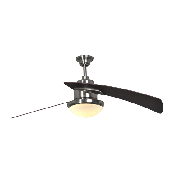
SANTA ANA CEILING FAN
Purchase Date ____________
1
ITEM #0464466
MODEL #LP8294LBN
Español p. 24
Lowes.com/harborbreeze
Publicidad
Capítulos
Tabla de contenido
Solución de problemas

Manuales relacionados para Harbor Breeze LP8294LBN


Resumen de contenidos para Harbor Breeze LP8294LBN
- Página 1 ITEM #0464466 SANTA ANA CEILING FAN MODEL #LP8294LBN Español p. 24 Harbor Breeze ® is a registered trademark of LF, LLC. All Rights Reserved. ATTACH YOUR RECEIPT HERE Serial Number ____________ Purchase Date ____________ Questions, problems, missing parts? Before returning to your retailer, call our customer service department at 1-800-643-0067, 8 a.m.
-
Página 2: Tabla De Contenido
TABLE OF CONTENTS Package Contents ............. . 3 Hardware Contents . -
Página 3: Package Contents
PACKAGE CONTENTS PART DESCRIPTION QUANTITY PART DESCRIPTION QUANTITY Motor Glass Hanger Bracket Blade Holder Arm Downrod Blade Ceiling Canopy Bulb Receiver (preassembled to Canopy Screw Cover Motor (A)) Motor Coupling Cover Remote Lower Housing Motor Coupler Washer Assembly (preassembled to Motor (A)) Upper Housing Cover Socket Plate Assembly (preassembled to Motor (A)) -
Página 4: Hardware Contents
HARDWARE CONTENTS (shown actual size) Screw Washer-Head Wire Balance Downrod Support Set Upper Housing Qty. 5 Screw Connector Kit (not Screw (preassembled Cover Screw Qty. 7 Qty. 4 shown to to Motor (A)) (preassembled size) Qty. 2 to Motor (A)) Qty. -
Página 5: Safety Information
SAFETY INFORMATION Please read and understand this entire manual before attempting to assemble, operate, or install the product. • Before you begin installing the fan, disconnect the power by removing fuses or turning off circuit breakers. • Make sure all electrical connections comply with local codes, ordinances, or the National Electrical code. -
Página 6: Preparation
SAFETY INFORMATION • To reduce the risk of fi re, electric shock, or personal injury, do not bend the blade arms when installing them, balancing the blades, or cleaning the fan. Do not insert foreign objects between the rotating fan blades. Mount the fan to an outlet box marked “ACCEPTABLE FOR FAN SUPPORT” and use mounting screws provided with the outlet box. -
Página 7: Initial Assembly Instructions
INITIAL ASSEMBLY INSTRUCTIONS 1. Remove the two preassembled downrod support set screws (EE) on the downrod support from the motor (A). Retain the screws for later. Hardware Used Downrod Support Set Screws 2. Remove the preassembled upper housing cover screws (FF) from the top of the motor (A). Retain these screws for later. - Página 8 INITIAL ASSEMBLY INSTRUCTIONS 4. Position the blade holder arm (J) over the motor (A) with threaded posts showing. Make sure the bottom edge of the blade holder arm (J) is fully seated against the fl ywheel of the motor (A). Attach the screws (AA) to secure the blade holder arm (J) to the fl...
- Página 9 INITIAL ASSEMBLY INSTRUCTIONS 7. Loosen the preassembled hanger ball set screw (GG) until the hanger ball falls freely down the downrod (C). Remove the preassembled hanger ball pin (HH) from the downrod (C) and remove the hanger ball portion of the downrod (C). Retain the hanger ball pin (HH) and hanger ball for later.
- Página 10 INITIAL ASSEMBLY INSTRUCTIONS 10. Thread the downrod (C) into the downrod support of the motor (A). Align the holes in the downrod support of the motor (A) with the holes in the downrod (C) and re-install the downrod pin (JJ). Secure the downrod pin (JJ) with the downrod clip (II).
- Página 11 INITIAL ASSEMBLY INSTRUCTIONS 12. Route the wires through the previously removed hanger ball. Insert the previously removed hanger ball pin (HH) through the two holes in the downrod (C) and align the hanger ball so the hanger ball pin (HH) is captured in the groove in the top of the downrod (C).
- Página 12 INITIAL ASSEMBLY INSTRUCTIONS WARNING: To avoid possible electrical shock, be sure electricity is turned off at the main fuse box before hanging. WARNING: If you are not sure if the outlet box is grounded, contact a licensed electrician for advice, as it must be grounded for safe operation. WARNING: The fan must hang with at least 7 ft.
-
Página 13: Wiring Instructions
WIRING INSTRUCTIONS WARNING: To avoid possible electrical shock, be sure electricity is turned off at the main fuse box before hanging. WARNING: If you are not sure if the outlet box is grounded, contact a licensed electrician for advice, as it must be grounded for safe operation. 1. -
Página 14: Final Assembly Instructions
FINAL ASSEMBLY INSTRUCTIONS 1. Remove one of the two preassembled shoulder screws (KK) in the hanger bracket (B). Loosen the second shoulder screw (KK) without fully removing it. Rotate the ceiling canopy (D) so the second shoulder screw (KK) moves into the small opening of the keyslot. - Página 15 FINAL ASSEMBLY INSTRUCTIONS 4. Place a blade (K) on the bottom of a blade holder arm (J), positioning the holes over the threaded posts. Tighten the washer-head screws (BB) to secure the blade (K) and blade holder arm (J). Repeat for the other blade (K).
-
Página 16: Operating Instructions
FINAL ASSEMBLY INSTRUCTIONS 7. Install the bulb (L) into the socket. CAUTION: Bulbs are pressurized and may shatter. DO NOT TOUCH BULBS WITH BARE HANDS. Fingerprints may result in shorter bulb life. Remove fi ngerprints with alcohol prior to use. To reduce the risk of fi re, use a 100- watt max. - Página 17 OPERATING INSTRUCTIONS 2. Remove the battery cover from the remote (N) and install the battery (Q), ensuring the polarity of the battery (Q) matches the polarity in the battery compartment. Replace the battery cover. Note: When it is time to replace battery (Q), use a 12-volt battery.
- Página 18 OPERATING INSTRUCTIONS 4. Remote (N) functions: Fan speed: 2 = Low speed 1 = Minimum speed 3 = Medium low speed 4 = Medium speed 5 = Medium high speed 6 = High speed = Natural breeze Tap either of the “ /1/2/3/4/5/6 ”...
-
Página 19: Blade Balancing Instructions
BLADE BALANCING INSTRUCTIONS 1. Interchanging positions of adjacent blades (K) can redistribute the weight and result in smoother operation. If wobble decreases, leave the blades (K) as they are. If wobble increases, switch back to the original position. Attach the balancing clip from the balance kit (DD) to the mid-point on the top edge of one blade (K). -
Página 20: Care And Maintenance
CARE AND MAINTENANCE WARNING: Do not use water when cleaning the ceiling fan. It could damage the motor or the fi nish and create the possibility of electrical shock. • When cleaning, use only a soft brush or lint-free cloth to avoid scratching the fi nish. •... -
Página 21: Troubleshooting
TROUBLESHOOTING PROBLEM POSSIBLE CAUSE CORRECTIVE ACTION The fan will not start. 1. The fuse or circuit breaker is 1. Check the main and branch circuit blown. fuses or circuit breakers. 2. There are loose power line 2. Check the line wire connections to connections to the fan. -
Página 22: Warranty
TROUBLESHOOTING PROBLEM POSSIBLE CAUSE CORRECTIVE ACTION The fan wobbles 1. The set screw in the downrod 1. Tighten the set screws securely in the excessively. support is loose. downrod support. 2. Tighten the set screw in the downrod/ 2. The set screw in the in hanger ball assembly. -
Página 23: Replacement Parts List
Blade Holder Arm 16LBN AP815004WA Blade PPE11B100 Bulb RECDC8294 Receiver Unit TR17 Remote HDWBH8150NI Screw Washer Head HDWBM8150NI Screw HDWWNUTS4 Wire Connector LBALKT Balance Kit Printed in China ® Harbor Breeze is a registered trademark of LF, LLC. All Rights Reserved. Lowes.com/harborbreeze... - Página 24 ARTÍCULO # 0464466 VENTILADOR DE TECHO SANTA ANA MODELO # LP8294LBN Harbor Breeze ® es una marca registrada de LF, LLC. Todos los derechos reservados. ADJUNTE SU RECIBO AQUÍ Número de serie ____________ Fecha de compra ____________ ¿Preguntas, problemas, piezas faltantes? Antes de volver a la tienda, llame a nuestro Departamento de Servicio al Cliente al 1-800-643-0067, de lunes a jueves de 8 a.m.
- Página 25 ÍNDICE Contenido del paquete ............26 Aditamentos .
-
Página 26: Contenido Del Paquete
CONTENIDO DEL PAQUETE PIEZA DESCRIPCIÓN CANTIDAD PIEZA DESCRIPCIÓN CANTIDAD Motor Vidrio Abrazadera para colgar Brazo de soporte del aspa Varilla Aspa Base para techo Bombilla Cubierta para el tornillo Receptor (preensamblado de la base en el motor (A)) Cubierta para el Control remoto acoplador del motor Arandela del acoplador del... - Página 27 ADITAMENTOS (se muestran en tamaño real) Tornillo Tornillo con Conector de Kit de Tornillo de la Cant. 5 cabeza de cables equilibrio (no soporte de la varilla cubierta de arandela Cant. 4 se muestra en (preensamblado la carcasa Cant. 7 tamaño real) en el motor (A)) superior...
-
Página 28: Información De Seguridad
INFORMACIÓN DE SEGURIDAD Lea y comprenda completamente este manual antes de intentar ensamblar, usar o instalar el producto. Antes de comenzar la instalación del ventilador, desconecte la alimentación eléctrica retirando los fusibles o colocando el interruptor de circuito en la posición de apagado. Asegúrese de que todas las conexiones eléctricas cumplan con los códigos u ordenanzas locales o el Código Eléctrico Nacional. -
Página 29: Preparación
INFORMACIÓN DE SEGURIDAD Para reducir el riesgo de incendios, descargas eléctricas o lesiones personales, no doble los brazos de las aspas al instalarlas, al equilibrarlas o al limpiar el ventilador. No introduzca objetos extraños entre las aspas en movimiento. Monte el ventilador en una caja de salida marcada como “ACCEPTABLE FOR FAN SUPPORT”... -
Página 30: Instrucciones De Ensamblaje Iniciales
INSTRUCCIONES DE ENSAMBLAJE INICIALES en el soporte de la varilla (EE) en el soporte de la varilla del motor (A). Guarde los tornillos para más adelante. Aditamentos utilizados del soporte de la varilla 2. Retire los tornillos preensamblados en la carcasa superior (FF) de la parte superior del motor (A). - Página 31 INSTRUCCIONES DE ENSAMBLAJE INICIALES Coloque el brazo de soporte del aspa (J) en el motor (A) con los postes roscados que se muestran. Asegúrese de que el borde inferior del brazo de soporte del aspa (J) esté completamente asentado sobre el volante del motor (A).
- Página 32 INSTRUCCIONES DE ENSAMBLAJE INICIALES preensamblada (GG) hasta que salga libremente de la varilla (C). Retire el pasador de la bola para colgar preensamblado (HH) de la varilla (C) y retire la parte de la varilla que posee la bola para colgar (C). Guarde el pasador de la bola para colgar (HH) y la bola para colgar para pasos posteriores.
- Página 33 INSTRUCCIONES DE ENSAMBLAJE INICIALES 10. Enrosque la varilla (C) en el soporte de la varilla y vuelva a instalar el pasador de la varilla (JJ). Fije el pasador de la varilla (JJ) y el sujetador de la varilla (II). Vuelva a instalar los dos tornillos de ADVERTENCIA: Es fundamental que instale correctamente el pasador de la varilla (JJ), y que apriete (EE).
- Página 34 INSTRUCCIONES DE ENSAMBLAJE INICIALES 12. Pase los cables por la bola para colgar que retiró anteriormente. Coloque el pasador de la bola para colgar que retiró anteriormente (HH) a través de para colgar para que el pasador (HH) quede inserto en la ranura de la parte superior de la varilla (C).
- Página 35 INSTRUCCIONES DE ENSAMBLAJE INICIALES ADVERTENCIA: Para evitar una posible descarga eléctrica, asegúrese de cortar la alimentación eléctrica de la caja de fusibles principal antes de colgar el ventilador. ADVERTENCIA: Si no está seguro de si la caja de salida tiene puesta a tierra, solicite ayuda ADVERTENCIA: Debe colgar el ventilador a una distancia mínima de 2,13 m desde el piso hasta las aspas.
-
Página 36: Instrucciones De Cableado
INSTRUCCIONES DE CABLEADO ADVERTENCIA: Para evitar una posible descarga eléctrica, asegúrese de cortar la alimentación eléctrica de la caja de fusibles principal antes de colgar el ventilador. ADVERTENCIA: Si no está seguro de si la caja de salida tiene puesta a tierra, solicite ayuda Conecte el conductor verde con conexión a tierra de la varilla (C) y el conductor verde con conexión a tierra de la abrazadera para colgar (B) al conductor... -
Página 37: Instrucciones De Ensamblaje Finales
INSTRUCCIONES DE ENSAMBLAJE FINALES Retire uno de los dos tornillos de reborde preensamblados tornillo de reborde (KK) sin retirarlo del todo. Gire la base para techo (D) de modo que el segundo tornillo de reborde (KK) se desplace a la abertura pequeña del chavetero. - Página 38 INSTRUCCIONES DE ENSAMBLAJE FINALES 4. Coloque un aspa (K) en la parte inferior de un brazo los postes roscados. Apriete los tornillos con cabeza de arandela (BB) para asegurar el aspa (K) y el brazo del soporte del aspa (J). Repite el procedimiento para la otra aspa (K).
-
Página 39: Instrucciones De Funcionamiento
INSTRUCCIONES DE ENSAMBLAJE FINALES 7. Instale la bombilla (L) en el portalámpara. PRECAUCIÓN: Las bombillas están presurizada y pueden quebrarse. NO TOQUE LAS BOMBILLAS CON LAS MANOS DESPROTEGIDAS. Las huellas dactilares en la bombilla pueden reducir la vida útil de la misma. Elimine las huellas dactilares con alcohol antes de usar la bombilla. - Página 40 INSTRUCCIONES DE FUNCIONAMIENTO 2. Retire la tapa de la batería del control remoto (N) e instale la batería (O), y asegúrese de que la polaridad de la batería (Q) sea igual a la polaridad del compartimiento para las mismas. Coloque de nuevo la cubierta de la batería.
- Página 41 INSTRUCCIONES DE FUNCIONAMIENTO 4. Funciones del control remoto (N): Velocidad del ventilador: 2 = Velocidad baja 1 = Velocidad mínima 3 = Velocidad media baja 4 = Velocidad media 5 = Velocidad media alta 6 = Velocidad alta = Brisa natural Presione cualquiera de los botones “...
-
Página 42: Instrucciones Para Equilibrar Las Aspas
INSTRUCCIONES PARA EQUILIBRAR LAS ASPAS 1. Intercambiar la posición de aspas adyacentes (K) puede redistribuir el peso y hacer que funcione más suavemente. Si el tambaleo disminuye, deje las aspas (K) como están. Si el tambaleo aumenta, vuelva a la posición original. Fije el sujetador de equilibrio del kit de equilibrio (DD) al punto medio en el borde superior de una de las aspas (K). -
Página 43: Cuidado Y Mantenimiento
CUIDADO Y MANTENIMIENTO ADVERTENCIA: No use agua para limpiar el ventilador de techo. Puede dañar el motor o el acabado y crear la posibilidad de una descarga eléctrica. Use solo una brocha suave o un paño que no produzca pelusas para evitar rayar el acabado al limpiarlo. -
Página 44: Solución De Problemas
SOLUCIÓN DE PROBLEMAS PROBLEMA CAUSA POSIBLE ACCIÓN CORRECTIVA El ventilador no 1. El fusible o el interruptor de 1. Revise los fusibles del circuito de circuito están fundidos. derivación y del circuito principal arranca. o los interruptores de circuito. 2. Alguna de las conexiones 2. -
Página 45: Garantía
SOLUCIÓN DE PROBLEMAS PROBLEMA CAUSA POSIBLE ACCIÓN CORRECTIVA El ventilador se tambalea del soporte de la varilla están soporte de la varilla. excesivamente. ensamble de la bola para colgar. ensamble de la bola para colgar/ 3. Los tornillos que sujetan los soportes de las aspas del soportes de las aspas del ventilador al ventilador al eje del motor están... -
Página 46: Lista De Piezas De Repuesto
Unidad receptora RECDC8294 Control remoto TR17 Tornillo HDWBH8150NI Tornillo con cabeza HDWBM8150NI de arandela Conector de cables HDWWNUTS4 Kit de equilibrio LBALKT Impreso en China ® Harbor Breeze es una marca registrada de LF, LLC. Todos los derechos reservados. Lowes.com/harborbreeze...