Tabla de contenido
Publicidad
Idiomas disponibles
Idiomas disponibles
Enlaces rápidos
Harbor Breeze® is a registered trademark
of LF, LLC. All Rights Reserved.
ATTACH YOUR RECEIPT HERE
Serial Number
Questions, problems, missing parts? Before returning to your retailer, call our customer
service department at 1-888-567-2055, 8 a.m. - 5 p.m., EST, Monday - Friday.
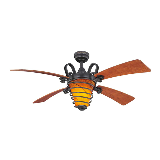
QUIMBY CEILING FAN
Purchase Date
ITEM #0331101
MODEL #LP8078LAZ
Español p. 22
Publicidad
Capítulos
Tabla de contenido
Solución de problemas

Manuales relacionados para Harbor Breeze QUIMBY LP8078LAZ


Resumen de contenidos para Harbor Breeze QUIMBY LP8078LAZ
- Página 1 ITEM #0331101 QUIMBY CEILING FAN MODEL #LP8078LAZ Harbor Breeze® is a registered trademark of LF, LLC. All Rights Reserved. Español p. 22 ATTACH YOUR RECEIPT HERE Serial Number Purchase Date Questions, problems, missing parts? Before returning to your retailer, call our customer...
-
Página 2: Tabla De Contenido
TABLE OF CONTENTS Safety Information ......................... Package Contents ......................... Hardware Contents ........................Preparation ........................... Assembly Instructions ........................Hanging Instructions ........................Wiring Instructions ........................Canopy Housing Installation ......................Blade Installation .......................... Light Kit Installation ........................Fan Operating Instructions ......................Blade Balancing Installation Instructions ..................Care and Maintenance ......................... -
Página 3: Safety Information
SAFETY INFORMATION Please read and understand this entire manual before attempting to assemble, operate or install the product. If you have any questions regarding the product, please call customer service at 1-888-567-2055, 8 a.m. - 5 p.m., EST, Monday - Friday. •... - Página 4 SAFETY INFORMATION (Continued) WARNING To reduce the risk of fire, electrical shock, or personal injury, wire connectors provided with this fan are designed to accept only one 12 gauge house wire and two lead wires from the fan. If your house wire is larger than 12 gauge or there is more than one house wire to connect to the two fan lead wires, consult an electrician for the proper size wire connectors to use.
-
Página 5: Package Contents
PACKAGE CONTENTS PART DESCRIPTION QUANTITY PART DESCRIPTION QUANTITY Motor Assembly Bulb Hanger Bracket Glass Downrod/Hanger Ball Receiver Unit Assembly Remote Ceiling Canopy Canopy Screw Cover Motor Coupling Cover Blade Holder Arm Blade Housing Upper Assembly Light Socket Plate Assembly... -
Página 6: Hardware Contents
HARDWARE CONTENTS (shown actual size) Fiber Washer-Head Washers Wire Screws Screws Connectors Qty. 13 Qty. 9 Qty. 4 Qty. 13 Balance (not shown to size) Qty. 1 PREPARATION Before beginning assembly of product, make sure all parts are present. Compare parts with. package contents list and diagram above. -
Página 7: Assembly Instructions
ASSEMBLY INSTRUCTIONS 1. Remove the hanger ball portion from the downrod/hanger ball assembly (C) by loosen- ing the set screw in the hanger ball until the ball falls freely down the downrod. Remove the pin from the downrod, then remove the hanger ball. - Página 8 ASSEMBLY INSTRUCTIONS (Continued) 4. Route wires through motor coupling cover (F), canopy screw cover (E) and ceiling canopy (D). (Fig. 4) 5. Reinstall the hanger ball on the downrod/hanger ball assembly (C) by routing the three 54 in. wires through the hanger ball. Position the pin from the downrod/hanger ball assembly (C) through the two holes in the downrod and align the hanger ball so the pin is...
-
Página 9: Hanging Instructions
HANGING INSTRUCTIONS WARNING To avoid possible electrical shock, be sure electicity is turned off at the main fuse box before hanging. NOTE: If you are not sure if the outlet box is grounded, contact a licensed electrician for advice, as it must be grounded for safe operaion. WARNING The fan must be hung with at least 7 ft. -
Página 10: Wiring Instructions
WIRING INSTRUCTIONS WARNING To avoid possible electrical shock, be sure electricity is turned off at the main fuse box before hanging. NOTE: If you are not sure if the outlet box is grounded, contact a licensed electrician for advice, as it must be grounded for safe operation. - Página 11 WIRING INSTRUCTIONS (Continued) 3. Slide the receiver unit (M) into the open end of the hanger bracket (B) (Fig. 3) 4. Connect green wires from hanger bracket (B) and downrod/hanger ball assembly (C) to bare (ground) wire using wire connector (DD). Connect black wire from receiver unit (M) marked “AC IN L”...
-
Página 12: Canopy Housing Installation
WIRING INSTRUCTIONS (Continued) 5. After connections have been made, turn leads upward and carefully push leads into the outlet box, with the white and green leads to one side of the box and the black leads toward the other side. The wires should be spread apart with the grounded conductor and the equipment- grounding conductor on one side of the outlet box and the ungrounded conductor on the other... -
Página 13: Blade Installation
BLADE INSTALLATION 1. Position the blade (H) over the blade holder arm (G) with threaded posts showing. Make sure the bottom edge of the blade (H) is fully seated against the blade holder arm (G). Tighten washer-head screws (BB) with fiber washers (CC) to secure the blade (H) to the blade holder arm (G). -
Página 14: Light Kit Installation
LIGHT KIT INSTALLATION 1. Remove one of the three screws in the adapter plate of motor assembly (A). Slightly loosen the remaining two screws. Assemble the housing upper assembly (I) to the fan motor assembly (A) using the two key slots. Replace the third screw and secure all three screws. -
Página 15: Fan Operating Instructions
LIGHT KIT INSTALLATION (Continued) 4. Install bulbs (K) into sockets. (Fig. 4) 5. Remove nut and finial from post on light socket plate assembly (J). Postion glass assembly (L) onto light socket plate assembly (J) and securely tighten the nut and finial from light socket plate assembly (J). - Página 16 FAN OPERATING INSTRUCTIONS (Continued) 2. To make fan operational, install 12-volt battery (included) in remote (N). Store the remote 12V BATTERY away from excessive heat or humidity. (Fig. 2) 3. The remote (N) includes five buttons for high, medium and low fan speeds as well as fan off and light on/off.
-
Página 17: Blade Balancing Installation Instructions
BLADE BALANCING INSTALLATION INSTRUCTIONS WARNING The balancing clip must always be firmly pushed onto the blade till it touches the edge of the blade. Failure to do so could allow clip to fly off and cause personal injury. 1. Interchanging positions of adjacent blades (H) can redistribute the weight and result in a smoother operation. -
Página 18: Care And Maintenance
CARE AND MAINTENANCE •When cleaning, use only a soft brush or lint-free cloth to avoid scratching the finish. •Abrasive cleaning agents are not required and should be avoided to prevent damage to finish. WARNING Do not use water when cleaning your ceiling fan. It could damage the motor or the finish and create the possibility of electrical shock. - Página 19 TROUBLESHOOTING (Continued) PROBLEM POSSIBLE CAUSE CORRECTIVE ACTION Fan sounds 4. Wire connectors inside 4. Check to make sure wire connectors in housing rattling. switch housing are not rattling against noisy each other or against the interior wall of the switch housing. WARNING Make sure main power is turned off! 5.
-
Página 20: Warranty
WARRANTY The manufacturer warrants this fan to be free from defects in workmanship and material present at time of shipment from the factory for life (with limitations) from the date of purchase. This warranty applies only to the original purchaser. The manufacturer agrees to correct such defect at no change or at our option replace the ceiling fan with a comparable or superior model. -
Página 21: Replacement Parts List
REPLACEMENT PARTS LIST For replacement parts, call our customer service department at 1-888-567-2055, 8 a.m. - 5 p.m., EST, Monday - Friday. PART DESCRIPTION PART # Motor Assembly AMA8078LAZ Hanger Bracket (with Screws) APGAC110RBL Hanger Ball/Downrod Assembly ADRACT1-45LAZ Ceiling Canopy P800501LAZ Canopy Screw Cover Assembly APPAC1101LAZ... -
Página 22: Ventilador De Techo Quimby
ARTÍCULO #0331101 VENTILADOR DE TECHO QUIMBY MODELO #LP8078LAZ Harbor Breeze® es una marca registrada de LF, LLC. Todos los derechos reservados. Adjuntar su recibo AQUÍ Número de serie Fecha de Compra ¿Preguntas, problemas, piezas faltantes? Antes de volver a la tienda, llame a nuestro Departamento de Servicio al Cliente al 1-888-567-2055, 8 a.m. -
Página 23: Especificaciones
ÍNDICE Información de seguridad ......................Contenido del paquete ......................... Aditamentos ..........................Preparación ..........................Instrucciones de ensamblaje ......................Instrucciones para colgar ......................Instrucciones de cableado ......................Instalación de la carcasa de la base .................... Instalación de las aspas ....................... Instalación del kit de iluminación ....................Instrucciones de funcionamiento de la cadena del tirador ............ -
Página 24: Información De Seguridad
INFORMACIÓN DE SEGURIDAD Lea y comprenda completamente este manual antes de intentar ensamblar, usar o instalar el producto. Si tiene preguntas relacionadas con el producto, llame a nuestro Departamento de Servicio al Cliente al 1-888-567-2055, 8 a.m. - 5 pm, hora del Este, de lunes - viernes. •... - Página 25 INFORMACIÓN DE SEGURIDAD (Continuación) recomienda al usuario corregir dichas interferencias tomando una o varias de las siguientes medidas: - Modificar la orientación o ubicación de la antena de recepción; - Aumentar la separación entre el equipo y el receptor; - Conectar el equipo a una toma de corriente o circuito diferente al del receptor; Consulte al distribuidor o a un técnico especialista de radio o TV para obtener más ayuda.
-
Página 26: Contenido Del Paquete
CONTENIDO DEL PAQUETE PIEZA DESCRIPCIÓN CANTIDAD PIEZA DESCRIPCIÓN CANTIDAD Ensamble del motor Bombilla Vidrio Abrazadera para colgar Unidad receptora Ensamble de la bola para colgar/varilla Escudo del techo Control remoto de mano Cubierta para los tornillo de la base Cubierta para el acoplador del motor Brazo de soporte del aspa Aspa Ensamble superior de la carcasa... -
Página 27: Aditamentos
ADITAMENTOS (Se muestan en tamaño real) Arandelas Tornillos con de fibra Conectores cabeza de Tornillos de cable arandela Cant. 9 Cant. 13 Cant. 4 Cant. 13 Kit de equilibrio (no se muestra en tamaño real) Cant. 1 PREPARACIÓN Antes de comenzar a ensamblar el producto, asegúrese de tener todas las piezas. Compare las piezas con la lista del contenido del paquete y el diagrama anterior. -
Página 28: Instrucciones De Ensamblaje
INSTRUCCIONES DE ENSAMBLAJE 1. Retire la parte correspondiente a la bola para colgar del ensamble de la bola para colgar/varilla(C) aflojando el tornillo de fijación de la bola hasta que ésta salga libremente de la varilla. Retire el pasador de la varilla y luego retire la bola para colgar. - Página 29 INSTRUCCIONES DE ENSAMBLAJE (Continuación) 4. Pase los cables a través de la cubierta del acoplador del motor (F), la cubierta del tornillo de la base (E) y la base para techo (D). (Fig. 4) 5. Vuelva a instalar la bola para colgar en el ensamble de la bola para colgar/varilla (C) haciendo pasar los tres conductores de 1,37 m a través de la bola para colgar.
-
Página 30: Instrucciones Para Colgar
INSTRUCCIONES PARA COLGAR ADVERTENCIA Para evitar una posible descarga eléctrica,asegúrese de cortar la alimentación eléctrica de la caja de fusibles principal antes de colgar el ventilador. NOTA: Si no está seguro de si la caja de salida tiene conexión a tierra, pida consejo a un electricista certificado, ya que debe tener conexión a tierra para un funcionamiento seguro. -
Página 31: Instrucciones De Cableado
INSTRUCCIONES DE CABLEADO ADVERTENCIA Para evitar una posible descarga eléctrica,asegúrese de cortar la alimentación eléctrica de la caja de fusibles principal antes de colgar el ventilador. NOTA: Si no está seguro de si la caja de salida NOTA: El control remoto de mano incluido con el tiene conexión a tierra, pida consejo a un ventilador cuenta con combinaciones de 16 electricista certificado, ya que debe tener... -
Página 32: Aditamentos Utilizados
INSTRUCCIONES DE CABLEADO (Continuación) 3. Deslice la unidad receptora (M) en el extremo abierto de la abrazadera para colgar (B). (Fig. 3) 4. Conecte los conductores verdes de la abrazadera para colgar (B) y el ensamble de bola para colgar/varilla (C) al conductor desnudo (a tierra) con el conector de cables (DD). -
Página 33: Instalación De La Carcasa De La Base
INSTRUCCIONES DE CABLEADO (Continuación) 5. Una vez realizadas las conexiones, gire los conductores hacia arriba y, con cuidado, colóquelos dentro de la caja de salida; con los Caja de salida Blanco homologada conductores blancos y verdes hacia un lado y los conductores negros hacia el otro. -
Página 34: Instalación De Las Aspas
INSTALACIÓN DE LAS ASPAS 1. Coloque las aspas (H) sobre sus soportes (G) con los postes roscados que se muestran. Asegúrese de que el borde inferior del aspa (H) esté completamente asentado sobre el brazo del aspa (G). Ajuste los tornillos con cabeza (BB) junto con las arandelas de fibra (CC) para asegurar las aspas(H) a los brazos del aspa (G). -
Página 35: Instalación Del Kit De Iluminación
INSTALACIÓN DEL KIT DE ILUMINACIÓN 1. Retire uno de los tres tornillos en la placa del adaptador en el ensamble del motor (A). Afloje ligeramente los dos tornillos restantes. Ensamble el ensamble superior de la carcasa (I) al ensamble del motor del ventilador (A) con los dos chaveteros. - Página 36 INSTALACIÓN DEL KIT DE ILUMINACIÓN (Continuación) 4. Coloque las bombillas (K) en los portalámparas. (Fig. 4) 5. Retire la tuerca y el remate de la varilla del ensamble de la placa del portalámpara (J). Coloque el ensamble de vidrio (L) en el ensamble de la placa del portalámpara (J) y apriete firmemente la tuerca y el remate del ensamble de la placa del portalámpara (J).
- Página 37 INSTRUCCIONES DE FUNCIONAMIENTO DEL VENTILADOR (Continuación) 2. Para que el ventilador esté operativo, instale una batería de 12 voltios en el control 12V batería remoto de mano (N). Almacene el control remoto alejado del calor y humedad extremos. (Fig. 2) 3.
-
Página 38: Instrucciones De Instalación De Aspa Equilibrada
INSTRUCCIONES DE INSTALACIÓN DE ASPA EQUILIBRADA ADVERTENCIA El sujetador de equilibrio siempre se debe empujar firmemente en el aspa hasta que toque el borde de ésta. Si no lo hace, el sujetador puede salir disparado y causar daños personales. 1. Intercambiar la posición de aspas adyacentes (H) puede redistribuir el peso y hacer que funcione más suavemente. -
Página 39: Cuidado Y Mantenimiento
CUIDADO Y MANTENIMIENTO •El único mantenimiento que necesita el ventilador de techo es la limpieza periódica. Use sólo una brocha suave o un paño sin pelusa para evitar rayar el acabado al limpiar. Los agentes limpiadores abrasivos son innecesarios y deben evitarse para no dañar el acabado. ADVERTENCIA No use agua para limpiar el ventilador de techo. - Página 40 SOLUCIÓN DE PROBLEMAS (Continuación) PROBLEMA CAUSA POSIBLE ACCIÓN CORRECTIVA El ventilador 4. Los conectores de cable de la 4. Compruebe que los conectores de carcasa repiquetean. cable de la carcasa del interruptor no emite mucho repiqueteen unos contra otros o contra ruido las paredes interiores de la carcasa del (Continuación)
-
Página 41: Garantía
GARANTÍA El fabricante garantiza, de por vida, (con limitaciones) que este ventilador no presenta defectos ni de fabricación ni en los materiales presentes en el momento del transporte desde la fábrica a partir de la fecha de compra. Esta garantía es válida sólo para el comprador original. El fabricante acepta reparar dichos defectos sin cargo o, según nuestro criterio, reemplazar el ventilador de techo por un modelo comparable o superior. -
Página 42: Lista De Piezas De Repuesto
LISTA DE PIEZAS DE REPUESTO Para obtener piezas de repuesto, llame a nuestro Departamento de Servicio al Cliente al 1-888-567-2055, 8 a.m. - 5 pm, hora del Este, de lunes - viernes. PIEZA DESCRIPCIÓN PIEZA # Ensamble del motor AMA8078LAZ Abrazadera para colgar (con tornillos) APGAC110RBL Ensamble de la bola para colgar/varilla...