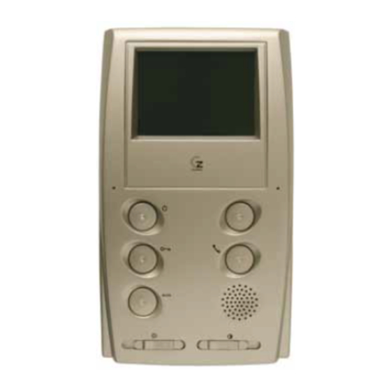
Guinaz M2710D Guia De Instalacion
Sistema modular videoportero dual manos libres
Ocultar thumbs
Ver también para M2710D:
- Guia de instalacion (16 páginas) ,
- Guia de instalacion (8 páginas) ,
- Guia de instalacion (20 páginas)
Publicidad
Enlaces rápidos
Publicidad

Resumen de contenidos para Guinaz M2710D
- Página 1 MODULAR DUAL HANDS-FREE VIDEO ENTRYPHONE SYSTEM GUÍA DE INSTALACIÓN INSTALLATION GUIDE...
- Página 2 CARACTERÍSTICAS Y FUNCIONAMIENTO. CHARACTERISTICS AND FUNCTIONING. Video entryphone (black and white or colour) installation for several dwellings with call confirmation in the street panel and automatic start-up of the monitor. Its functioning and installation are simple. The steps for installation are shown in the different sections, with a street panel offering several adjustments for each type of installation, such as the position of the camera, sound volume, etc.
- Página 3 INSTALACIÓN PLACA CALLE. INSTALLATION OF THE STREET PANEL. Assembly the flush Separate the covers, loosen both screws and Insert modules and joints in the same order mounted box. extract the joints of the modules. as in the figure. To open towards the right. Unscrew Attach the left screw and loosen the right one.
- Página 4 COLOCACIÓN DE LOS TARJETEROS. PLACEMENT OF NAME TAGS. Separate Insert the card. translucent glass part. Insert in the push-button Extract the name card unit module until it clips in. from the push-button module of the street panel. The street panel is sufficiently protected against atmospheric conditions.
- Página 5 INSTALACIÓN DE FUENTE DE ALIMENTACIÓN. INSTALLATION OF POWER SUPPLY. The power supply can be installed on a DIN slide or by means of sleeper-screws into the wall, always internally. INSTALACIÓN MONITORES. INSTALLATION OF MONITORS. Assemble this wall base panel on the wall using four Configure the connection card of the wall base as indicated sleeper-screws and connect it to the connection card.
- Página 6 ESQUEMA UNIFILAR. SINGLE WIRE DIAGRAM. Coaxial or Twisted pair 5+(n-1) Video signal distributor Coaxial or Twisted pair Distributor power supply Coaxial or Twisted pair n= No. of dwellings DOOR OPENER SPECIFICATIONS. The system allows the use of electric door openers compliant with the following specifications: Voltage: 12VAC Maximum current: 0,8A CONFIGURACIÓN TELECÁMARA.
- Página 7 ESQUEMA DE CONEXIONES. CONNECTION DIAGRAM. M2710D M2710D Do no shut-off the resistance M1934 M2710D M2710D Shut-off the resistance POWER SUPPLY CABLE. M1934 SIGNAL CABLE. 75 Ohm COAXIAL CABLE. Configuration for coaxial cable. F1320 G1810D F1318 G1220 G02XX Additional door opener push-button...
- Página 8 TABLA DE SECCIONES. SECTION TABLE. Minimum sections Distance Connections Nº of wires nPUL NOTE: These sections accept the installation of a supplementary monitor per dwelling. Coaxial or Twisted pair INSTALACIÓN TELÉFONO SUPLETORIO. INSTALLATION OF A SUPPLEMENTARY TELEPHONE. POWER SUPPLY CABLE. T1105 SIGNAL CABLE.
- Página 9 EJEMPLO DE DISTRIBUCIÓN DE SEÑAL DE VÍDEO EN CASCADA. EXAMPLE OF RISE VIDEO SIGNAL DISTRIBUTION. Special care must be taken when configuring the bridge in each wall base (see page 6). Coaxial Twisted pair M2710D/ M2740D 75 Ohm coaxial or cat. 5 Twisted pair cable.
- Página 10 Specific 4-branch distributors, ref. M1934 for 75 ohm coaxial cable. Special care must be taken when configuring the bridge in each wall base (see page 6). The closure resistance will be cut in all distributors in which the video cable enters and exits towards another distributor. M2710D M2710D M2740D...
- Página 11 Special care must be taken when configuring the bridge in each wall base (see page 6). The closure resistance will be cut in all distributors in which the video cable enters and exits towards another distributor. J2 (100 ohm) J2 (100 ohm) M2710D M2710D M2740D M2740D...
- Página 12 SOLUCIÓN DE PROBLEMAS. PROBLEM SOLVING. PROBLEM POSSIBLE FAULT ± Nothing works. Check the voltages between terminal blocks 1-2 (12 VAC) and between 11-5F (16VDC± 1VDC) in the power supplies. If there are problems with any of these outputs, disconnect the PRIM cables, wait for one minute and reconnect them. Should the problem persist, check the installation connections.


