Publicidad
Idiomas disponibles
Idiomas disponibles
APPLICATION
This wiring modifi cation is available for models T, J and H (for
1 Phase, 3 Phase and 575V Logic 5.0 operators).
This brake kit will either replace an existing brake or add a brake to an
operator that does not have a brake (1/3 or 1/2 HP). This design may
differ from a caliper style brake being replaced.
If a brake is being replaced, many of the kit components and wiring may
be reused from the existing operator (wiring harness, conduit, etc.).
INSTALLATION
1. Disconnect power to operator.
2. Remove the belt and motor pulley from the motor shaft.
3. If Brake Kit is being used to replace an existing brake, the original
brake assembly must be removed, including the square brake hub. A
small gear puller makes removal of the hub easier. Smooth any burrs
on the shaft with a fi le.
4. Refer to brake plate spacing guidelines on page 2 to assure belt/pulley
alignment. Spacing is important to ensure the brake drum can be
installed fl ush to the brake shoes.
5. Install brake assembly onto motor and hand tighten with the 4 nuts
provided.
6. Install brake drum on the motor shaft. Activate brake plunger if
necessary for easier install. Insert key stock and set screw to lock
brake drum in place. Once the brake drum is installed and centered,
tighten the 4 brake assembly nuts. Ensure the drum is not installed
too far into the assembly making contact with the assembly plate; this
will cause the drum to rub while it spins, creating noise and possible
premature wear/failure.
7. Install motor pulley on motor shaft. The clutch pulley and motor pulley
must be aligned in the same plane. If necessary, loosen the motor
mounting bolts to assist with alignment and re-tighten.
8. Install the belt and secure the set screws into the motor pulley.
Set Screw
Motor
Pulley
Key Stock
Belt
Brake Drum
Right Handed H Operator
Left Handed H Operator
Brake Solenoid
Motor
Shaft
Clutch Pulley
LOGIC 5.0 DRUM BRAKE KIT INSTRUCTIONS
To prevent possible SERIOUS INJURY or DEATH, disconnect electric
power to operator BEFORE installing.
ALL installations and electrical connections MUST be made by a
trained door systems technician.
WARNING: This product can expose you to chemicals including
lead, which are known to the State of California to cause cancer
or birth defects or other reproductive harm. For more information
go to www.P65Warnings.ca.gov
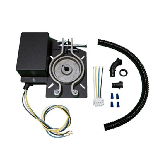
DESCRIPTION
Instructions ........................................................................................1
Solenoid Brake Assembly ...................................................................1
Brake Release Cable Kit ......................................................................1
Brake Drum ........................................................................................1
Cable Sleeve .......................................................................................1
Thread locker .....................................................................................1
Wire Harness Assembly Kit ................................................................1
Wire Harness Conduit ........................................................................1
Cable Tie ............................................................................................2
Flatwasher #10 ...................................................................................4
Brake Adapters
must be added for
575V Motors
Brake
Plunger
Motor
Mounting
Bolts
1
FOR MODELS: T, J AND H
K71-D1PH, K71-D3PH, AND K71-D575-1
CARTON INVENTORY
Brake Assembly
Nuts
QTY
Publicidad
Tabla de contenido

Manuales relacionados para LiftMaster K71-D1PH


Resumen de contenidos para LiftMaster K71-D1PH
- Página 1 LOGIC 5.0 DRUM BRAKE KIT INSTRUCTIONS FOR MODELS: T, J AND H K71-D1PH, K71-D3PH, AND K71-D575-1 APPLICATION This wiring modifi cation is available for models T, J and H (for 1 Phase, 3 Phase and 575V Logic 5.0 operators). To prevent possible SERIOUS INJURY or DEATH, disconnect electric power to operator BEFORE installing.
- Página 2 BRAKE PLATE SPACING REQUIREMENTS Install the brake assembly, using #10 fl atwashers where necessary (included, see Figure 2), to ensure it is properly seated on the motor and the belt is straight between the motor and clutch pulley. Clutch Pulley Belt Motor Pulley AO SMITH / REGAL BELOIT MOTORS (STANDARD LOGIC...
- Página 3 WIRING Before removing solenoid wiring, take note of existing wiring connections. The wiring for the new solenoid will be identical. If the brake is being replaced, you may reuse existing wiring/conduit and skip Steps 3-10. BRAKE SOLENOID TO CONNECTOR 1. Remove brake solenoid cover to expose the terminals. Connect the (Single Phase) solenoid wires as shown.
- Página 4 RELEASE CABLE INSTALLATION RELEASE CABLE SLEEVE ROUTING FOR H MODEL OPERATORS ONLY 1. Locate the screw threads protruding through the brake mounting plate opposite the brake solenoid. Mount the new cable clamp to the thread that is second from the top and closest the motor. Secure in place with the #10 fl...
- Página 5 INSTRUCTIONS POUR LA TROUSSE DU FREIN À TAMBOUR LOGIC 5.0 POUR MODÈLES: T, J ET H K71-D1PH, K71-D3PH, ET K71-D575-1 APPLICATION Cette modifi cation de câblage est offerte pour les modèles T, J et H (pour actionneurs monophasés, triphasés et de 575 V Logic 5.0).
- Página 6 EXIGENCES D’ESPACEMENT DE LA PLAQUE DE FREINAGE Installer l’ensemble de frein avec des rondelles plates no 10 au besoin (incluses, voir Figure 2) pour garantir qu’il est correctement assis sur le moteur et que la courroie est droite entre le moteur et la poulie d’embrayage.
- Página 7 CÂBLAGE Avant d’enlever le câblage du solénoïde, prendre note des connexions de câblage existantes. Le câblage du solénoïde neuf sera identique. Si le frein est remplacé, il est possible de réutiliser le câble/la conduite existant(e); SOLÉNOÏDE DE FREIN AU CONNECTEUR sauter les étapes 3 à...
- Página 8 INSTALLATION DU CÂBLE DE DESSERRAGE ACHEMINEMENT DU MANCHON DU CÂBLE DE DESSERRAGE POUR LES OPÉRATEURS DE MODÈLE H EXCLUSIVEMENT 1. Repérer les vis droites fi letées qui ressortent de la plaque de montage du frein du côté opposé au solénoïde de frein. Monter le collier de câble neuf sur la deuxième vis fi...
-
Página 9: Instalación
INSTRUCCIONES DEL JUEGO DE FRENO DE TAMBOR LOGIC 5.0 PARA LOS MODELOS: T, J y H K71-D1PH, K71-D3PH, Y K71-D575-1 APLICACIÓN Esta modifi cación del cableado está disponible para los modelos T, J y H (para operadores Logic 5.0 monofásicos, trifásicos y de 575 V). -
Página 10: Para Operadores Destinados A Ambientes
REQUISITOS DEL ESPACIADO DEL DISCO DE FRENO Instale el conjunto de freno, usando las arandelas planas #10 (incluidas, vea Firgura 2) donde sea necesario, para garantizar que esté debidamente asentado en el motor y que la correa esté recta entre el motor y la polea del embrague. - Página 11 CABLEADO Antes de retirar el cableado del solenoide, tome nota de las conexiones de cableado existentes. El cableado del solenoide nuevo será el mismo. Si está reemplazando el freno, puede volver a utilizar el cableado/conducto existente y omitir los Pasos del 3 al 10. SOLENOIDE DE FRENO AL CONECTOR (Monofásico) 1.
- Página 12 Perno de movimiento no se escuche el zumbido. Un solenoide que zumba afecta resorte el solenoide y puede causar una falla prematura. © 2017, LiftMaster All Rights Reserved Tous droits réservés 01-39108B Todos los derechos reservados...