Tabla de contenido
Publicidad
Idiomas disponibles
Idiomas disponibles
Enlaces rápidos
Publicidad
Capítulos
Tabla de contenido

Manuales relacionados para Nilfisk-Advance 7765 Serie


Resumen de contenidos para Nilfisk-Advance 7765 Serie
- Página 1 7765 Instructions for Use Instrucciones de uso MODELS: 56514925 , 56514926 , 56514927 (VD Gas) (VD LP) (VD Diesel) 56514928 , 56514929 , 56514930 (MD Gas) (MD LP GM3.0L) (MD Diesel S4Q2) 56514931 (VD LP) A-English B-Español 5/09 revised 1/14 Form No. 56041801 REV A...
-
Página 2: Tabla De Contenido
A-2 / ENGLISH TABLE OF CONTENTS Page Table of Contents ..............A-2 - A-3 Introduction .................. A-4 Introduction ................A-4 Parts and Service ..............A-4 Nameplate ................A-4 Un-Crating ................A-4 Machine Operation ..............A-5 Preparing the Machine for Operation........A-5 Cautions and Warnings............... A-6 Consignes De Prudence Et De Securite ........A-7 Operation of Controls and Gauges .........A-8 –... - Página 3 ENGLISH / A-3 TABLE OF CONTENTS Page Scrubbing System Operating Instructions ....A-16 – A-18 ESP System Operating Instructions ........A-16 ESP Recycling Control Panel ..........A-16 ESP Recycling System On/Off Switch ........A-16 Solution High Warning Light ..........A-16 Detergent Low Warning Light ..........A-16 Detergent Flow Knob ............A-16 The Scrubbing System - How It Works .......A-17 Non-Recycling Scrubbing System - How It Works ....A-17...
-
Página 4: Introduction
A-4 / ENGLISH INTRODUCTION This manual will help you get the most from your Advance sweeper / scrubber. Read it thoroughly before operating the machine. PARTS AND SERVICE Repairs, when required, should be performed by your Authorized Advance Service Center, who employs factory trained service personnel, and ™... -
Página 5: Machine Operation
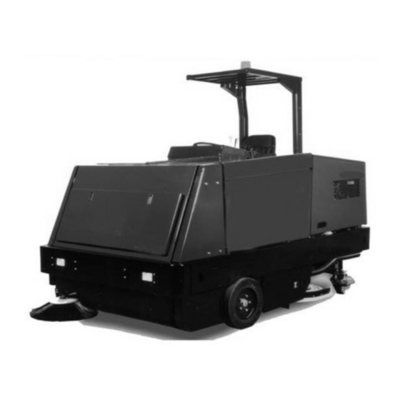
ENGLISH / A-5 MACHINE OPERATION FIGURE 1 YOUR 7765 MACHINE HAS BEEN SHIPPED COMPLETE, BUT DO NOT ATTEMPT TO OPERATE WITHOUT FOLLOWING THESE INSTRUCTIONS. PREPARING THE MACHINE FOR OPERATION Connect and tighten battery cables. Fill the tank with REGULAR GRADE unleaded gasoline; Diesel fuel if equipped with diesel engine. WARNING Never fi... -
Página 6: Cautions And Warnings
A-6 / ENGLISH CAUTIONS AND WARNINGS SYMBOLS Advance uses the symbols below to signal potentially dangerous conditions. Always read this information carefully and take the ™ necessary steps to protect personnel and property. DANGER! Is used to warn of immediate hazards that will cause severe personal injury or death. WARNING! Is used to call attention to a situation that could cause severe personal injury. -
Página 7: Consignes De Prudence Et De Securite
ENGLISH / A-7 CONSIGNES DE PRUDENCE ET DE SECURITE SYMBOLES Advance utilise les symboles reproduits ci-dessous pour attirer l’attention de l’opérateur sur des situations potentiellement dangereuses. Il est ™ donc conseillé de lire attentivement ces indications et de prendre les mesures adéquates en vue de protéger le personnel et le matériel. DANGER ! Ce symbole est utilisé... -
Página 8: Operation Of Controls And Gauges
A-8 / ENGLISH OPERATIONS OF CONTROLS AND GAUGES Water Temperature Gauge Check Engine Light (Gasoline/LP) Hour Meter Turn Signal Fuel Gauge Throttle Diesel Oil Pressure Gauge Throttle Gasoline/LP Volt Meter Solution Control Main Broom Switch Sweeping Broom Lift Control Side Broom Switch ESP Option Dust Control Switch AA Detergent Flow Knob... -
Página 9: Turn Signal (Option)
ENGLISH / A-9 OPERATIONS OF CONTROLS AND GAUGES 4-WAY TURN SIGNAL (OPTION) The Turn Signal Option (U) is located on the steering column and works as automotive turn signals work, forward on the lever for right and back on the lever for left. The 4-way fl asher will activate when the turn signal lever is pulled out. GLOW PLUG SWITCH (DIESEL) Under no circumstances should any other unauthorized starting aids be used at the same time as Glow Plugs. -
Página 10: Main Broom Switch
A-10 / ENGLISH OPERATIONS OF CONTROLS AND GAUGES MAIN BROOM SWITCH The Main Broom Switch (F) is located on the console to the right of the steering wheel in the SWEEPING section. This switch will activate the Main Broom. This switch has two positions “ON” and “OFF”. See Sweeping Broom Lift Control. SIDE BROOM SWITCH (OPTION FOR MANUAL DUMP MACHINES) The Side Broom Switch (G) is located on the console to the right of the steering wheel in the SWEEPING section. -
Página 11: Water Temperature Gauge
ENGLISH / A-11 OPERATIONS OF CONTROLS AND GAUGES WATER TEMPERATURE GAUGE The Water Temperature Gauge (A) is located on the console panel above the steering wheel in the gauge cluster. The gauge is mechanical and activated by a sender in the engine. It displays the engine coolant temperature in Fahrenheit. HOUR METER The Hour Meter (B) is located on the console panel above the steering wheel in the gauge cluster. -
Página 12: Scrub Brushes Switch
A-12 / ENGLISH OPERATIONS OF CONTROLS AND GAUGES SCRUB BRUSHES SWITCH The Brushes Switch (AK) is located on the console to the left of the steering wheel in the “SCRUBBING” section. This switch in the position marked “LOWER” will lower the scrub brush deck and activate the three scrub brushes. The Brush Rotation Switch (AM) and the Brush Pressure Switch (AJ) can not be activated unless this switch is in the “LOWER”... -
Página 13: Hopper Lift
ENGLISH / A-13 OPERATIONS OF CONTROLS AND GAUGES HOPPER LIFT - (VARIABLE MACHINES ONLY) The Hopper Lift Lever (AF) is located to the left of the steering wheel on the left side of the driver compartment. This lever, which is marked “HOPPER”, raises and lowers the debris hopper to ease unloading. -
Página 14: Throttle
A-14 / ENGLISH OPERATIONS OF CONTROLS AND GAUGES THROTTLE CONTROL See Figure 2. The Throttle Control (V or W) is located on the left side console. Gas and LP equipment have a Throttle Switch (W). Diesel versions have a Lever (V). To operate the diesel: For full throttle, grasp the lever and push up and right to the locking notch. To reduce to idle, grasp the lever and push it up and to the left (away from the locking notch). -
Página 15: Accelerator & Directional Control Pedal
ENGLISH / A-15 OPERATIONS OF CONTROLS AND GAUGES FIGURE 10 ACCELERATOR & DIRECTIONAL CONTROL PEDAL See Figure 2. The Accelerator and Directional Control Pedal (Q) is located on the fl oor of the driver compartment, to the right of the brake pedal. The accelerator and directional control pedal controls machine direction and travel speed. -
Página 16: Scrubbing System Operating Instructions
A-16 / ENGLISH SCRUBBING SYSTEM OPERATING INSTRUCTIONS THE ESP RECYCLING CONTROL PANEL HIGH RECYCLING SYSTEM SOLUTION DETERGENT FLOW DETERGENT FIGURE 11 THE ESP RECYCLING SYSTEM ON/OFF SWITCH See Figure 11. The ESP Recycling System ON/OFF Switch (A) turns the ESP recycling system on and off. SOLUTION HIGH WARNING LIGHT The Solution High Warning Light (B) will come on if the solution tank is too full of water from the recycling system. -
Página 17: The Scrubbing System - How It Works
ENGLISH / A-17 SCRUBBING SYSTEM OPERATING INSTRUCTIONS NON-RECYCLING RECYCLING FIGURE 12 Recovery Tank THE SCRUBBING SYSTEM - HOW IT WORKS Solution Tank There are two scrubbing systems available for the 7765 machine, the non-recycling or Baffl e standard scrubbing system and the recycling or ESP scrubbing system. Detergent Tank Check Valve THE NON-RECYCLING OR STANDARD SCRUBBING... - Página 18 A-18 / ENGLISH SCRUBBING SYSTEM OPERATING INSTRUCTIONS THE RECOVERY OR ESP SCRUBBING SYSTEM - HOW IT WORKS During the scrubbing process (shown in Figure 15), fi ltered water from the solution tank is fed to the solution line, where it combines with detergent from the metering pump.
-
Página 19: Dust Control Operating Instructions
ENGLISH / A-19 DUST CONTROL OPERATING INSTRUCTIONS THE VARIABLE DUMP SWEEPING AND DUST CONTROL SYSTEMS - HOW THEY WORK Variable Dump 7765 machines are equipped with a sweeping and dust control system. Figure 16 shows the highest position for the variable dump. -
Página 20: Operating Instructions
A-20 / ENGLISH OPERATING INSTRUCTIONS FILLING THE SOLUTION TANK NON-RECYCLING OR STANDARD SCRUBBING SYSTEM Make sure the solution control lever is in the “Off” (rear) position. Open the solution tank cover (right hand side). Fill the tank with 100 gallons (378 L) of water and the correct mixture of Advance #100 Industrial Cleaner for the job. Close the solution tank cover. -
Página 21: Post-Start Checklist
ENGLISH / A-21 OPERATING INSTRUCTIONS POST-START CHECKLIST (ENGINE RUNNING) Check main and side brooms to make sure they are free of debris which will inhibit rotation & pick-up. NOTE: Always wear hand protection when cleaning debris from brooms and/or brushes. Check squeegees to make sure there is no damage and they meet the fl... -
Página 22: Helpful Hints For Cleaning Operation
A-22 / ENGLISH OPERATING INSTRUCTIONS HELPFUL HINTS FOR CLEANING OPERATION SIDE AISLES MAIN AISLE SIDE AISLES FIGURE 18 WARNING Do not turn the steering wheel sharply when the machine is in motion. The sweeper is very responsive to movement of the steering wheel. Do not make sudden turns. Scrub in straight paths. -
Página 23: Post-Operation & Clean-Up Instructions
ENGLISH / A-23 POST-OPERATION & CLEAN-UP INSTRUCTIONS TO STOP THE CLEANING OPERATION Discontinue the cleaning operation whenever a solution or recovery warning or stop light is illuminated. The solution light will illuminate when the solution tank is empty. At this time, discontinue the scrubbing cycle, put all controls in position for transport and drive to the drain area. -
Página 24: To Clean The Recovery Tank
A-24 / ENGLISH POST-OPERATION & CLEAN-UP INSTRUCTIONS TO CLEAN RECOVERY TANK The large access cover on the recovery tank simplifi es the cleaning process. Once the recovery tank lid is opened, tip out the tank. With the recovery tank in the tipped out position (Figure 19), fl ush all sand, sludge, debris, etc. out of the tank with a water hose, then replace the tank and fl... -
Página 25: To Empty The Debris Hopper
ENGLISH / A-25 POST-OPERATION & CLEAN-UP INSTRUCTIONS TO EMPTY DEBRIS HOPPER Transport or sweep and scrub to the dump site. Close the hopper dump door with the hopper dump lever. Raise the hopper with the hopper lift lever to the desired level. Move the machine forward, over the dumpster, if necessary. -
Página 26: Service Chart
A-26 / ENGLISH SERVICE CHART For service assistance, consult the yellow pages under power sweepers and scrubbers. For best performance, replace worn parts with genuine Advance parts. EVERY 8 HOURS or DAILY operation check and clean/adjust if necessary: Inspect panel fi lters for damage and clean. Check engine oil level. - Página 27 ENGLISH / A-27 SERVICE CHART 2, 25 39 36, 37 11, 34 13, 35 15, 33 1, 7, 24 41, 42, 43 12, 40 28, 30 6, 23 FIGURE 22 FORM NO. - 56041801 - 7765 - A-27...
-
Página 28: General Machine Maintenance
A-28 / ENGLISH GENERAL MACHINE MAINTENANCE Lubrication Points - FIGURE 23 LUBRICATION 100 Hour Lubrication Lubricate drive wheel swivel, wheel bearings and steering rack guide (see next page). Lubricate front wheel bearings. Lubricate all moving joints. Lubricate all bushings with Loctite Silver Grade Anti-Seize compound. - Página 29 ENGLISH / A-29 GENERAL MACHINE MAINTENANCE LUBRICATION OF STEERING RACK GUIDE WARNING Make sure the steering system and surrounding components are cool to the touch before attempting to grease the steering system lubrication fi ttings. Failure to observe this safety precaution can result in severe burns. Grease the Rack (A), and the Lubrication Fittings (B &...
-
Página 30: Engine
A-30 / ENGLISH GENERAL MACHINE MAINTENANCE ENGINE Read and follow all the instructions in the Engine Manual Section. Due to the nature of work being done by the machine, extra care must be taken to protect the engine from these elements. Check the oil each day before starting operations. Be sure to check the air fi lter cap’s dust collector and empty as necessary. -
Página 31: Main Broom Level Adjustment
ENGLISH / A-31 GENERAL MACHINE MAINTENANCE MAIN BROOM LEVEL ADJUSTMENT The main broom level is factory set and shouldn’t need adjustment, if the level gets out of adjustment and the broom bristle contact pattern is not an even 2” to 3” (5 to 8 cm.) wide. Adjust the broom arm lift frame. The frame is supported by two fl... -
Página 32: Flaps
A-32 / ENGLISH GENERAL MACHINE MAINTENANCE 1/16" (1.6 mm) FIGURE 26 FLAPS The urethane and rubber fl aps are susceptible to damage and should be inspected regularly and maintained in good condition. The side fl aps are adjustable and should be maintained at approximately 1/16” (1.6 mm.) above the fl oor. Set fl... -
Página 33: Scrub Brush Replacement
ENGLISH / A-33 GENERAL MACHINE MAINTENANCE FIGURE 27 SCRUB BRUSH REPLACEMENT 1. Raise the scrub brush deck by pressing the “Scrub Brush” Switch on the instrument panel. 2. Press the Brush Latches (A) in to release the scrub brush. 3. Remove old scrub brush. 4. -
Página 34: Recycling Pump Esp System
A-34 / ENGLISH GENERAL MACHINE MAINTENANCE RECYCLING PUMP ESP SYSTEM The recycling pump is located directly behind and under the recovery tank. The pump is electric and except for daily cleaning of the pump intake screens, it requires no regular maintenance. NOTE Do not run pump dry. -
Página 35: General Troubleshooting
ENGLISH / A-35 GENERAL TROUBLESHOOTING PROBLEM PROBABLE CAUSE REMEDY Sweeping does not 1. Dump door closed 1. Open dump door function 2. Hopper is raised 2. Lower hopper 3. Hopper switch out of adjustment 3. Adjust hopper switch Poor water pick up at 1. - Página 36 A-36 / ENGLISH GENERAL TROUBLESHOOTING PROBLEM PROBABLE CAUSE REMEDY Poor scrubbing 1. Worn scrubbing brushes 1. Inspect brushes. If worn to ½” (1.3cm) or less, replace all 3 brushes 2. Incorrect method of operation 2. Check scrubbing procedures, brush pressure, type of brush, solution fl ow, & cleaning chemical used.
- Página 37 ENGLISH / A-37 TECHNICAL SPECIFICATIONS (as installed and tested on the unit) Model 7765 Petrol (Variable Dump) 7765 LPG (Variable Dump) Model No. 56514925 56514926 Sound Pressure Level dB (A) (IEC 60335-2-72: 2002 Amend. 1:2005, ISO 11201) Sound Power Level dB (A) Lwa 109.0 Lwa 109.0...
- Página 38 B-2 / ESPAÑOL ÍNDICE Página Índice B-2 - B-3 Introducción ....................B-4 Introducción ..................B-4 Componentes y servicio ..............B-4 Placa de identifi cación ..............B-4 Desembalaje ..................B-4 Funcionamiento de la máquina ...............B-5 Preparación de la máquina para su uso ..........B-5 Precauciones y advertencias ..............B-6 Uso de los controles e indicadores ..........B-8 –...
-
Página 39: Índice
ESPAÑOL / B-3 ÍNDICE Página Instrucciones de uso del sistema de fregado ......B-16 – B-18 Instrucciones de uso del sistema ESP ..........B-16 Panel de control de reciclaje ESP ..........B-16 Interruptor de encendido/apagado del sistema de reciclaje ESP ..B-16 Luz de advertencia de mucha solución .........B-16 Luz de advertencia poco detergente ..........B-16 Botón de fl... -
Página 40: Introducción
B-4 / ESPAÑOL INTRODUCCIÓN Este manual le ayudará a obtener el máximo rendimiento de su limpiadora/barredora Advance . Léalo con atención antes de utilizar la máquina. ™ COMPONENTES Y SERVICIO Las reparaciones, cuando sean necesarias, deben ser realizadas por su centro de servicio técnico de Advance , que utiliza personal de servicio ™... -
Página 41: Funcionamiento De La Máquina
ESPAÑOL / B-5 FUNCIONAMIENTO DE LA MÁQUINA FIGURA 1 SU MÁQUINA 7765 SE HA ENVIADO COMPLETA, PERO NO INTENTE UTILIZARLA SIN RESPETAR LAS SIGUIENTES INSTRUCCIONES. PREPARACIÓN DE LA MÁQUINA PARA SU USO Conecte y apriete los cables de la batería. Llene el depósito con gasolina sin plomo NORMAL, o con combustible diesel si su motor es de este tipo. -
Página 42: Precauciones Y Advertencias
B-6 / ESPAÑOL PRECAUCIONES Y ADVERTENCIAS SÍMBOLOS Advance utiliza los símbolos que aparecen a continuación para indicar situaciones potencialmente peligrosas. Lea siempre con ™ atención esta información y tome las medidas necesarias para la protección de las personas y la propiedad. ¡PELIGRO! Se utiliza para advertir de riesgos inmediatos que producirán lesiones personales graves o incluso fatales. - Página 43 ESPAÑOL / B-7 FORM NO. - 56041801 - 7765 - B-7...
-
Página 44: Funciones De Los Controles E Indicadores
B-8 / ESPAÑOL FUNCIONES DE LOS CONTROLES E INDICADORES Indicador de temperatura del agua Luz de comprobación del motor (gasolina/ Medidor de horas de funcionamiento propano líquido) Indicador de combustible Intermitente Manómetro del aceite Acelerador, diesel Voltímetro Acelerador, gasolina/propano líquido Interruptor del cepillo principal Control de la solución Interruptor del cepillo lateral... -
Página 45: Funciones De Los Controles E Indicadores Intermitente De Giro De 4 Posiciones (Opcional)
ESPAÑOL / B-9 FUNCIONES DE LOS CONTROLES E INDICADORES INTERMITENTE DE GIRO DE 4 POSICIONES (OPCIONAL) La opción de intermitente de giro (U) está ubicada en la columna de dirección y funciona igual que los intermitentes de giro de un coche: si se mueve la palanca hacia adelante, se indica giro a la derecha, y hacia atrás se indica giro la izquierda. -
Página 46: Interruptor Del Cepillo Principal
B-10 / ESPAÑOL FUNCIONES DE LOS CONTROLES E INDICADORES INTERRUPTOR DEL CEPILLO PRINCIPAL El interruptor del cepillo principal (F) está situado en la consola, a la derecha del volante, en la sección SWEEPING (barrido). Este interruptor activa el cepillo principal. El interruptor tiene dos posiciones, encendido (“ON”) y desconexión (“OFF”). Consulte Control de elevación del cepillo de barrido. -
Página 47: Indicador De Temperatura Del Agua
ESPAÑOL / B-11 FUNCIONES DE LOS CONTROLES E INDICADORES INDICADOR DE TEMPERATURA DEL AGUA El indicador de temperatura del agua (A) está situado en el panel de la consola, sobre el volante, en el grupo de indicadores. El indicador es mecánico y se activa mediante un transmisor ubicado en el motor. -
Página 48: Interruptor De Cepillos De Fregado
B-12 / ESPAÑOL FUNCIONES DE LOS CONTROLES E INDICADORES INTERRUPTOR DE LOS CEPILLOS DE FREGADO El interruptor de los cepillos (AK) está situado en la consola, a la izquierda del volante, en la sección “SCRUBBING” (fregado). Si el interruptor se sitúa en la posición marcada como “LOWER”... -
Página 49: Elevación De La Tolva
ESPAÑOL / B-13 FUNCIONES DE LOS CONTROLES E INDICADORES ELEVACIÓN DE LA TOLVA (SOLO PARA MÁQUINAS VARIABLES) La palanca de elevación de la tolva (AF) está situada a la izquierda del volante, en el lado izquierdo del compartimento del conductor. Esta palanca, marcada como “HOPPER”, sube y baja la tolva de residuos para facilitar la descarga. -
Página 50: Luz De Comprobación Del Motor
B-14 / ESPAÑOL FUNCIONES DE LOS CONTROLES E INDICADORES CONTROL DE ACELERACIÓN Consulte la fi gura 2. El control de aceleración (V o W) está situado en la consola lateral izquierda. Los equipos de gasolina y propano líquido cuentan con un interruptor de aceleración (W). Las versiones diesel tienen una palanca (V). Para utilizar el modelo diesel: para lograr una aceleración máxima, tome la palanca y empuje hacia arriba y hacia la derecha, hasta la muesca de bloqueo. -
Página 51: Pedal Acelerador Y De Control Direccional
ESPAÑOL / B-15 FUNCIONES DE LOS CONTROLES E INDICADORES FIGURA 10 PEDAL ACELERADOR Y DE CONTROL DIRECCIONAL Consulte la fi gura 2. El pedal acelerador y de control direccional (Q) está situado en el suelo del compartimento del conductor, a la derecha del pedal del freno. -
Página 52: Instrucciones De Uso Del Sistema De Fregado
B-16 / ESPAÑOL INSTRUCCIONES DE USO DEL SISTEMA DE FREGADO EL PANEL DE MANDO DE RECICLAJE ESP HIGH RECYCLING SYSTEM SOLUTION DETERGENT FLOW DETERGENT FIGURA 11 EL INTERRUPTOR DE ENCENDIDO/APAGADO DEL SISTEMA DE RECICLAJE ESP Consulte la fi gura 11. El interruptor de encendido/apagado del sistema de reciclaje ESP (A) enciende y apaga el sistema de reciclaje ESP. LUZ DE ADVERTENCIA DE MUCHA SOLUCIÓN La luz de advertencia de mucha solución (B) se enciende si el depósito de la solución está... -
Página 53: Sin Reciclaje
ESPAÑOL / B-17 INSTRUCCIONES DE USO DEL SISTEMA DE FREGADO SIN RECICLAJE CON RECICLAJE FIGURA 12 Depósito de recuperación EL SISTEMA DE FREGADO: CÓMO FUNCIONA Depósito de la solución Hay dos sistemas de fregado disponibles para la máquina 7765: el sistema de fregado Defl... -
Página 54: Sistema De Fregado Con Recuperación O Esp: Cómo Funciona
B-18 / ESPAÑOL INSTRUCCIONES DE USO DEL SISTEMA DE FREGADO EL SISTEMA DE FREGADO CON RECUPERACIÓN O ESP: CÓMO FUNCIONA Durante el proceso de fregado (que se muestra en la fi gura 15) el agua fi ltrada procedente del depósito de la solución se suministra a la conducción de la solución, donde se combina con detergente procedente de la bomba de medición. -
Página 55: Instrucciones De Uso Del Control Del Polvo
ESPAÑOL / B-19 INSTRUCCIONES DE USO DEL CONTROL DE POLVO LOS SISTEMAS DE BARRIDO CON DESCARGA VARIABLE Y CONTROL DEL POLVO: CÓMO FUNCIONAN Las máquinas con descarga variable 7765 están equipadas con un sistema de barrido y control del polvo. La fi gura 16 muestra la posición más elevada para la descarga variable. -
Página 56: Instrucciones De Uso
B-20 / ESPAÑOL INSTRUCCIONES DE USO LLENADO DEL DEPÓSITO DE LA SOLUCIÓN SISTEMA DE FREGADO SIN RECICLAJE O ESTÁNDAR Asegúrese de que la palanca de control de la solución está en la posición de desconexión (trasera). Abra la cubierta del depósito de la solución (lado derecho) Rellene del depósito con 378,5 litros de agua y la mezcla correcta de limpiador industrial Advance #100 para el trabajo. -
Página 57: Lista De Comprobación Posterior A La Puesta En Marcha
ESPAÑOL / B-21 INSTRUCCIONES DE USO LISTA DE COMPROBACIÓN POSTERIOR A LA PUESTA EN MARCHA (MOTOR EN FUNCIONAMIENTO) Compruebe los cepillos principal y lateral para asegurarse de que no presentan residuos que impidan el giro y la aspiración. NOTA: lleve siempre protección en las manos al limpiar residuos de los cepillos. Compruebe las rasquetas para asegurarse de que no están dañadas y se adaptan al suelo. -
Página 58: Consejos Útiles Para La Operación De Limpieza
B-22 / ESPAÑOL INSTRUCCIONES DE USO CONSEJOS ÚTILES PARA LA OPERACIÓN DE LIMPIEZA PASILLOS LATERALES PASILLO PRINCIPAL PASILLOS LATERALES FIGURA 18 ADVERTENCIA No gire el volante bruscamente cuando la máquina esté en movimiento. La barredora es muy sensible al movimiento del volante. No realice giros repentinos. Friegue en línea recta. -
Página 59: Instrucciones Tras El Funcionamiento Y Para Limpieza
ESPAÑOL / B-23 INSTRUCCIONES TRAS EL FUNCIONAMIENTO Y PARA LIMPIEZA PARA DETENER LA OPERACIÓN DE LIMPIEZA Detenga la operación de limpieza siempre que se ilumine una luz de advertencia de solución o recuperación o una luz de parada. La luz de la solución se ilumina cuando el depósito de la solución está vacío. En ese momento, detenga el ciclo de fregado, sitúe todos los controles en posición de transporte y conduzca hasta el área de vaciado. -
Página 60: Para Limpiar El Depósito De Recuperación
B-24 / ESPAÑOL INSTRUCCIONES TRAS EL FUNCIONAMIENTO Y PARA LIMPIEZA PARA LIMPIAR EL DEPÓSITO DE RECUPERACIÓN La gran cubierta de acceso del depósito de recuperación simplifi ca el proceso de limpieza. Una vez abierta la tapa del depósito de recuperación, incline dicho depósito. -
Página 61: Para Vaciar La Tolva De Residuos
ESPAÑOL / B-25 INSTRUCCIONES TRAS EL FUNCIONAMIENTO Y PARA LIMPIEZA PARA VACIAR LA TOLVA DE RESIDUOS Transporte o barra y friegue hasta el lugar de descarga. Cierre la puerta de descarga de la tolva con la palanca de descarga de la tolva. Eleve la tolva con la palanca de elevación de la tolva hasta el nivel deseado. -
Página 62: Tabla De Mantenimiento
B-26 / ESPAÑOL TABLA DE MANTENIMIENTO Para obtener ayuda acerca de mantenimiento, consulte las páginas amarillas de barredoras y fregadoras propulsadas. Para obtener el mejor rendimiento, sustituya las piezas desgastados por piezas auténticas de Advance. CADA 8 HORAS de funcionamiento o A DIARIO, compruebe y limpie/ajuste si es necesario: Inspeccione si los fi... - Página 63 ESPAÑOL / B-27 TABLA DE MANTENIMIENTO 2, 25 39 36, 37 11, 34 13, 35 15, 33 1, 7, 24 41, 42, 43 12, 40 28, 30 6, 23 FIGURA 22 FORM NO. - 56041801 - 7765 - B-27...
-
Página 64: Mantenimiento General De La Máquina
B-28 / ESPAÑOL MANTENIMIENTO GENERAL DE LA MÁQUINA Puntos de Lubricación - FIGURA 23 LUBRICACIÓN Lubricación a las 100 horas Lubrique la rueda de tracción, los cojinetes de la rueda pivotante y la guía de la cremallera de la dirección (ver página siguiente). Lubrique los cojinetes de la rueda delantera. - Página 65 ESPAÑOL / B-29 MANTENIMIENTO GENERAL DE LA MÁQUINA LUBRICACIÓN DE LA GUÍA DE LA CREMALLERA DE DIRECCIÓN ADVERTENCIA Asegúrese de que el sistema de dirección y los componentes que lo rodean estén fríos al tacto antes de intentar engrasar los accesorios de lubricación del sistema de dirección.
-
Página 66: Motor
B-30 / ESPAÑOL MANTENIMIENTO GENERAL DE LA MÁQUINA MOTOR Lea y respete todas las instrucciones en la sección del manual del motor. Debido la naturaleza del trabajo que realiza la máquina, hay que tener un cuidado especial para proteger el motor de estos elementos. Compruebe el aceite cada día antes de comenzar las operaciones. Asegúrese de comprobar el colector de polvo de la tapa del fi... -
Página 67: Ajuste Del Nivel Del Cepillo Principal
ESPAÑOL / B-31 MANTENIMIENTO GENERAL DE LA MÁQUINA AJUSTE DEL NIVEL DEL CEPILLO PRINCIPAL El nivel del cepillo principal se ajusta en fábrica y no debería necesitar ajustes; si el nivel se desajusta y el patrón de contacto de las cerdas del cepillo no tiene una anchura regular de 5 a 8 cm: ajuste el bastidor de elevación del brazo del cepillo. -
Página 68: Aletas
B-32 / ESPAÑOL MANTENIMIENTO GENERAL DE LA MÁQUINA 1/16" (1.6 mm) FIGURA 26 ALETAS Las aletas de uretano y goma son susceptibles de sufrir daños, y deben inspeccionarse regularmente y mantenerse en buen estado. Las aletas laterales son ajustables y deben mantenerse aproximadamente a 1,6 mm sobre el suelo. Ajuste la aleta de forma regular respecto al suelo (A). -
Página 69: Sustitución Del Cepillo De Fregado
ESPAÑOL / B-33 MANTENIMIENTO GENERAL DE LA MÁQUINA FIGURA 27 SUSTITUCIÓN DEL CEPILLO DE FREGADO 1. Eleve el portacepillos de fregado presionando el interruptor “Scrub Brush” (cepillo de fregado) en el panel de instrumentos. 2. Presione los seguros del cepillo (A) hacia dentro para soltar el cepillo de fregado. 3. -
Página 70: Sistema Esp De Bomba De Reciclaje
B-34 / ESPAÑOL MANTENIMIENTO GENERAL DE LA MÁQUINA SISTEMA DE BOMBA DE RECICLAJE O ESP La bomba de reciclaje está situada directamente detrás y debajo del depósito de recuperación. La bomba es eléctrica y, excepto por la limpieza diaria de las cribas de admisión de la bomba, no requiere ningún mantenimiento regular. NOTA No haga funcionar la bomba en seco. -
Página 71: Resolución De Problemas Generales
ESPAÑOL / B-35 RESOLUCIÓN DE PROBLEMAS GENERALES PROBLEMA CAUSA PROBABLE SOLUCIÓN El barrido no funciona 1. Puerta de descarga cerrada 1. Abra la puerta de descarga 2. La tolva está elevada 2. Baje la tolva 3. Interruptor de la tolva mal ajustado 3. - Página 72 B-36 / ESPAÑOL RESOLUCIÓN DE PROBLEMAS GENERALES PROBLEMA CAUSA PROBABLE SOLUCIÓN Mal fregado 1. Cepillos de fregado desgastados 1. Inspeccione los cepillos. Si se han desgastado hasta 1,3 cm o menos, cambie los 3 cepillos 2. Método de trabajo incorrecto 2.
- Página 73 ESPAÑOL / B-37 ESPECIFICACIONES TÉCNICAS (SEGÚN LA INSTALACIÓN DE LA UNIDAD Y LAS PRUEBAS A LAS QUE SE HA SOMETIDO) 7765 LPG (propano líquido) Modelo 7765 gasolina (descarga variable) (descarga variable) Nº de modelo 56514925 56514926 Nivel de presión sonora dB (A) (IEC 60335-2-72: 2002 Amend.
- Página 80 Nilfi sk-Advance Equipamentos de Limpeza Ltda. Av. Dep. Emílio Carlos, 2.499 - Bairro do Limão - 02721-200 14600 21st Avenue North São Paulo - SP - Brasil Plymouth, MN 55447-3408 www.nilfi sk-advance.ind.br www.advance-us.com www.plataforma.ind.br Phone: 800-989-2235 Tel.: (11) 3959-0300 Fax: 800-989-6566 Fax: (11) 3959-0306 ©2014 Nilfi...