
Manuales relacionados para HT SOLAR-02


Resumen de contenidos para HT SOLAR-02
- Página 1 USER SOLAR-02 MANUAL SOLAR-02 ENVIRONMENTAL PARAMETER DATA LOGGER USER MANUAL Rel. 4.00 - 21/11/22 Rel. 4.00 - 22/11/22...
-
Página 2: Tabla De Contenido
UTILIZZO DELL'UNITA’ REMOTA SOLAR-02 MANUTENZIONE SPECIFICHE TECNICHE ASSISTENZA INTRODUCTION PRECAUTIONS AND SAFETY MEASURES PREPARATION FOR USE DESCRIPTION OF THE REMOTE UNIT SOLAR-02 USING THE REMOTE UNIT SOLAR-02 MAINTENANCE TECHNICAL SPECIFICATIONS SERVICE INTRODUCCIÓN PRECAUCIONES Y MEDIDAS DE SEGURIDAD PREPARACIÓN AL USO DESCRIPCIÓN DE LA UNIDAD REMOTA SOLAR-02... - Página 3 EINSATZ DES SOLAR-02 WARTUNG TECHNISCHE SPEZIFIKATIONEN SERVICE INTRODUCTION PRÉCAUTIONS ET MESURES DE SÉCURITÉ PRÉPARATION À L'UTILISATION DESCRIPTION DE L'UNITE A DISTANCE SOLAR-02 UTILISATION DE L'UNITE A DISTANCE SOLAR-02 ENTRETIEN SPÉCIFICATIONS TECHNIQUES ASSISTANCE INTRODUÇÃO PRECAUÇÕES E MEDIDAS DE SEGURANÇA PREPARAÇÃO PARA UTILIZAÇÃO DESCRIÇÃO DA UNIDADE REMOTA SOLAR-02...
- Página 4 5.2.2. Impostazione valori sensore 2 (MULTI) 5.2.3. Impostazione valori sensore 5.3. Uso del SOLAR-02 in modo indipendente 5.4. Uso della funzione inclinometro 5.5. Uso del SOLAR-02 con strumento MASTER Tipo “M-USB” 5.5.1. Controlli preliminari 5.5.2. Uso dello strumento 5.6. Uso del SOLAR-02 con strumento Master Tipo “M-RF”...
-
Página 5: Introduzione
• Misurazione angolo di inclinazione di pannelli FV ATTENZIONE • L’unità remota SOLAR-02 è uno strumento di misura e, come dispositivo, esso può anche intenzionalmente usare una radiofrequenza per il trasferimento dei dati. Per decisioni progettuali è stata adottata la banda di frequenza armonizzata di 2.4GHz. -
Página 6: Precauzioni Emisure Di Sicurezza
• Controllare che le batterie siano inserite correttamente ATTENZIONE La connessione RF dell’unità remota SOLAR-02 è per default disabilitata. Per l’uso di tale unità con strumenti Master tipo “M-RF” (vedere Tabella 1) è necessario abilitare la connessione RF (vedere § 5.6.1) -
Página 7: Durante L'uTilizzo
IT IT PRECAUZIONI SOLAR-02 E MISURE DI SICUREZZA DURANTE L'UTILIZZO La preghiamo di leggere attentamente le raccomandazioni e le istruzioni seguenti: ATTENZIONE • La mancata osservazione delle avvertenze e/o istruzioni può danneggiare lo strumento e/o i suoi componenti o essere fonte di pericolo per l’operatore •... -
Página 8: Descrizione Unita' Remota Solar
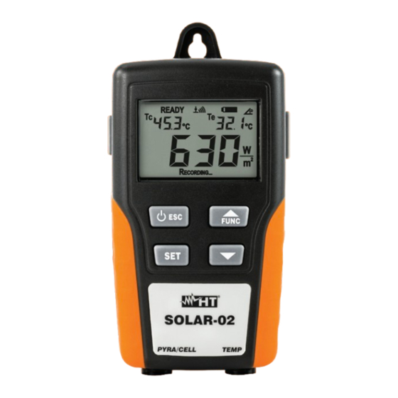
DESCRIZIONE SOLAR-02 UNITA' REMOTA SOLAR-02 DESCRIZIONE DEI COMANDI LEGENDA: 1. Display LCD 2. Tasto /ESC 3. Tasto SET 4. Ingresso PYRA/CELL 5. Ingresso TEMP 6. Tasto freccia ▼ 7. Tasto FUNC/▲ 8. Uscita USB per collegamento a strumento master M-USB TASTO MODE Questo tasto consente la doppia funzione di ON/OFF dell’unità... -
Página 9: Utilizzo Dell'UNita' Remota Solar
PYRA/CELL dell’unità. I valori impostati saranno letti e considerati dagli strumenti master in fase di collaudo/registrazione e saranno mantenuti dal SOLAR-02 anche con unità spenta fino ad una nuova modifica. L’unità SOLAR-02 permette l’impostazione dei parametri di max 3 sensori di irraggiamento. -
Página 10: Impostazione Valori Sensore 1 (Pyra O Mono)
SOLAR-02 5.2.1 IMPOSTAZIONE VALORI SENSORE 1 (PYRA O MONO) 1. Tenere premuto il tasto SET mentre si accende lo strumento con il tasto /ESC. L’unità presenta la videata a fianco. 2. Usare i tasti freccia ▲e ▼ per impostare il valore corretto del (Sensitivity) riportato sull’etichetta (frontale o posteriore) posta sul sensore stesso. -
Página 11: Uso Del Solar-02 In Modo Indipendente
/ESC. La seguente videata è mostrata a display 2. Premere il tasto FUNC/▲per attivare la modalità di inclinometro dell’unità SOLAR-02 in luogo della misura della temperatura Te come mostrato nella videata a fianco 3. Fissare l’unità sul piano del modulo sfruttando eventualmente la coppia di calamite presenti nella parte posteriore 4. -
Página 12: Uso Dello Strumento
(vedere § 5.2) 3. Confermare la scelta con il tasto SET 4. Collegare l’unità SOLAR-02 allo strumento Master tramite il cavo USB. Il simbolo “USB” è presente a display mentre l’unità sarà riconosciuta dallo strumento master 5. -
Página 13: Utilizzo Dello Strumento
“Recording…”. E’ ora possibile allontanare l’unità SOLAR-02 dall’unità Master e portarla in prossimità dei moduli FV. Gli eventuali trattini “- - -“ indicano che all’unità SOLAR-02 non sono ancora collegate le sonde di irraggiamento e temperatura 7. Posizionare la sonda per misura di irraggiamento tipo Irr-P o Irr-S2 (vedere Tabella 1) sul piano dei moduli e collegare il rispettivo terminale di uscita all’ingresso PYRA/CELL dell’unità... -
Página 14: Manutenzione
“ a display indica che le batterie interne sono scariche ed occorre sostituirle. A tal fine procedere come segue: 1. Spegnere l’unità remota SOLAR-02 2. Rimuovere ogni sonda presente sugli ingressi e l’eventuale cavo USB 3. Aprire il coperchio del vano batteria nella parte posteriore dell’accessorio 4. -
Página 15: Specifiche Tecniche
<80%RH Questo strumento è conforme alle Direttive LVD 2014/35/EU e EMC 2014/30/EU HT dichiara (vedere Declaration of Conformity) che lo strumento è conforme ai requisiti essenziali ed alle altre prescrizioni della Direttiva 1999/5/CE Questo strumento è conforme ai requisiti della direttiva europea 2011/65/EU (RoHS) e della... -
Página 16: Assistenza
ASSISTENZA SOLAR-02 CONDIZIONI DI GARANZIA Questo strumento è garantito contro ogni difetto di materiale e fabbricazione, in conformità con le condizioni generali di vendita. Durante il periodo di garanzia, le parti difettose possono essere sostituite, ma il costruttore si riserva il diritto di riparare ovvero sostituire il prodotto. Qualora lo strumento debba essere restituito al servizio post - vendita o ad un rivenditore, il trasporto è... - Página 17 SOLAR-02 Rel. 4.00 - 22/11/22...
- Página 18 5.2.3. Setting the values of sensor 3 5.3. Using the SOLAR-02 in independent mode 5.4. Using the inclinometer function 5.5. Using the SOLAR-02 with master instrument type “M-USB” 5.5.1. Preliminary check 5.5.2. Use of the unit 5.6. Using the SOLAR-02 with master instrument type “M-RF”...
-
Página 19: Introduction
It can also be used in combination with a MASTER instrument to carry out the above-mentioned measurements for testing/recording the efficiency of single-phase and three-phase photovoltaic installations. The unit SOLAR-02 can be connected to the following accessories and MASTER instruments: TABLE 1:... -
Página 20: Precautions And Safety Measures
• Check that the batteries are correctly inserted CAUTION The RF connection of remote unit SOLAR-02 is normally disabled for default. For use of this unit with the Master meter “M-RF” (see Table 1) is necessary to activate the RF connection (see § 5.6.1) -
Página 21: Preparation For Use
SOLAR-02 DURING USE We recommend carefully reading the following recommendations and instructions: CAUTION • Failure to observe the warnings and/or instructions may damage the instrument and/or its components or generate a danger for the operator. • The symbol « » indicates that the batteries are flat. Stop testing and replace the batteries according to the procedure described in §... -
Página 22: Description Of The Remote Unit Solar
DESCRIPTION OF THE SOLAR-02 REMOTE UNIT SOLAR-02 DESCRIPTION OF CONTROLS CAPTION: 1. LCD display /ESC key 3. SET key 4. PYRA/CELL input 5. TEMP input 6. ▼ arrow key 7. FUNC/▲ key 8. USB port for connection to master instrument M-USB... -
Página 23: Using The Remote Unit Solar
PYRA/CELL input of the unit. The set values will be read and considered by the master instruments upon testing/recording and will be kept by the SOLAR-02 even when the unit is turned off, until they are modified. -
Página 24: Setting The Values Of Sensor 1 (Pyra Or Mono)
SOLAR-02 5.2.1 SETTING THE VALUES OF SENSOR 1 (PYRA OR MONO) 1. Press and hold the SET key while turning on the instrument by means of the /ESC key. The unit shows the screen beside. 2. Use the arrow keys ▲and ▼to set the correct K sensitivity value reported on the (front or rear) label, located on the sensor itself. -
Página 25: Using The Solar-02 In Independent Mode
2. Press the FUNC/▲key to activate the inclinometer mode of the unit SOLAR-02 instead of the measurement of temperature Te as shown on the screen beside 3. Fasten the unit on the module’s surface, if necessary by means of the two magnets available on the rear side 4. -
Página 26: Use Of The Unit
3. Confirm selection with the SET key to go back to the measuring mode 4. Connect the unit SOLAR-02 to the master instrument by means of the USB cable. The symbol “USB” is shown on the display while the unit is detected by the master instrument 5. -
Página 27: Use Of The Unit
6. Once the waiting phase (HOLD) has ended, the message “Recording…” will be displayed. It is now possible to take the unit SOLAR-02 away from the master instrument and take it near the PV modules. Possible hyphens “- - -”... -
Página 28: Maintenance
MAINTENANCE SOLAR-02 GENERAL INFORMATION 1. Whether in use or in storage, please do not exceed the specifications to avoid any possible damage or danger during use. 2. Do not keep this instrument at high temperatures and/or humidity or expose it to direct sunlight. -
Página 29: Technical Specifications
<80%RH This instrument complies with LVD 2014/35/EU and EMC 2014/30/EU Directive HT declares (see Declaration of Conformity) that the instrument is complying with prerequisites and other requirements of 1999/5/CE Directive This instrument satisfies the requirements of 2011/65/EU (RoHS) directive and 2012/19/EU... -
Página 30: Service
SERVICE SOLAR-02 WARRANTY CONDITIONS This instrument is guaranteed against material or production defects, in accordance with our general sales conditions. During the warranty period, the manufacturer reserves the right to decide either to repair or replace the product. Should you need, for any reason, to return the instrument for repair or replacement, please take prior agreements with the local distributor from whom the instrument was bought. - Página 31 SOLAR-02 Rel. 4.00 - 22/11/22...
- Página 32 5.2.3. Configuración valores sensor 3 5.3. Uso del SOLAR-02 En modo independiente 5.4. Uso de la función inclinómetro 5.5. Uso del SOLAR-02 con instrumento MASTER Tipo “M-USB” 5.5.1. Controles preliminares 5.5.2. Uso del instrumento 5.6. Uso del SOLAR-02 con instrumento Master Tipo “M-RF”...
-
Página 33: Introducción
• Medición ángulo de inclinación del panel FV ATENCIÓN • La unidad remota SOLAR-02 es un instrumento de medición y, como un dispositivo, también puede utilizar intencionalmente una frecuencia de radio de transferencia de datos. A las decisiones de diseño HT se adoptó la banda de frecuencias armonizada de 2.4GHz. -
Página 34: Precaucionesy Medidas De Seguridad
• Controle que las pilas estén insertadas correctamente. CAUTION La conexión RF de la unidad remota SOLAR-02 está deshabilitada por defecto. Para el uso de tal unidad con instrumentos Master del tipo “M- RF” (ver Tabla 1) es necesario habilitar la conexión RF (ver § 5.6.1) -
Página 35: Preparación Al Uso
Si fuese necesario sustituir el instrumento, siga las instrucciones mostradas en § 8. ALIMENTACIÓN DE LA UNIDAD REMOTA SOLAR-02 El instrumento está alimentado a través 4x1.5V pilas tipo IEC LR03 AAA. Cuando las pilas están casi agotadas aparece el símbolo “... -
Página 36: Descripción De La Unidad Remota Solar
DESCRIPCIÓN DE LA UNIDAD REMOTA SOLAR-02 SOLAR-02 DESCRIPCIÓN DE LOS COMANDOS LEYENDA: 1. Visualizador LCD /ESC key 2. Tecla 3. Tecla SET 4. Entradas PYRA/CELL 5. Entrada TEMP input 6. Tecla flecha ▼ 7. Tecla FUNC/▲ 8. Salida USB para el conexionad al instrumento master M-USB DESCRIPCIÓN DE LA TECLAS FUNCIONES... -
Página 37: Uso De La Unidad Remota Solar
• Medido por la sonda PT300N • Calculado sobre la base del NOCT configurado en la unidad MASTER y de la irradiación y Temp. ambiente medidas por el SOLAR-02 mismo según la relación: Tcel =Tamb + (NOCT - 20) x... -
Página 38: Configuración Valores Sensor 1 (Pyra O Mono)
SOLAR-02 5.2.1 CONFIGURACIÓN VALORES SENSOR 1 (PYRA O MONO) 1. Tenga pulsada la tecla SET mientras se enciende el instrumento con la tasto /ESC. La unidad presenta la pantalla siguiente. 2. Use las teclas flecha ▲y ▼para configurar el valor correcto del (Sensitivity) mostrado sobre la etiqueta (frontal o posterior) sobre el mismo sensor. -
Página 39: Uso Del Solar-02 En Modo Independiente
1. Encienda la unidad con la tecla /ESC. La siguiente pantalla es mostrada 2. Pulse la tecla FUNC/▲ para activar la modalidad de inclinómetro de la unidad SOLAR-02 de la medida de la temperatura Te como muestra la pantalla siguiente 3. -
Página 40: Uso Del Instrumento
6. Terminada la fase de espera (HOLD) será visualizado el mensaje “Recording…”. Es ahora posible desconectar el cable USB de la unidad SOLAR-02 y llevarlo cerca de los módulos Fv. Los eventuales guiones “- - -“ indican que la unidad SOLAR-02 no están todavía conectadas las sondas de irradiación y temperatura... -
Página 41: Utilización Del Instrumento
6. Terminada la fase de espera (HOLD) será visualizado el mensaje “Recording…”. Es ahora posible desconectar el cable USB de la unidad SOLAR-02 y llevarlo cerca de los módulos Fv. Los eventuales guiones “- - -“ indican que la unidad SOLAR-02 no están todavía conectadas las sondas de irradiación y temperatura... -
Página 42: Mantenimiento
MANTENIMIENTO SOLAR-02 GENERALIDADES 1. Durante el uso y el almacenamiento respete las recomendaciones listadas en este manual para evitar posibles daños o peligros durante el uso 2. No utilice el instrumento en ambientes caracterizados por una elevada tasa de humedad o temperatura elevada. No exponga directamente a la luz del sol 3. -
Página 43: Especificaciones Técnicas
<80%RH Este instrumento es conforme en directivas LVD 2014/35/EU y EMC 2014/30/EU HT declara (ver Declaración de Conformidad) que el instrumento es conforme con los requisitos esenciales y otros requisitos de la Directiva 1999/5/CE Este instrumento es conforme a los requisitos de la Directiva Europea 2011/65/EU (RoHS) y... -
Página 44: Asistencia
ASISTENCIA SOLAR-02 CONDICIONES DE GARANTÍA Este instrumento está garantizado contra todo defecto de materiales y fabricación, conforme con las condiciones generales de venta. Durante el período de garantía, las partes defectuosas pueden ser sustituidas, pero el fabricante se reserva el derecho de repararlo o bien sustituir el producto. Si el instrumento debe ser reenviado al servicio postventa o a un distribuidor, el transporte es a cargo del Cliente. - Página 45 SOLAR-02 Rel. 4.00 - 22/11/22...
- Página 46 5.2.1. Setzen der Werte von Sensor 1 (PYRA oder MONO) 5.2.2. Einstellen der Werte von Sensor 2 (MULTI) 5.2.3. Einstellen der Werte von Sensor 3 5.3. Das SOLAR-02 im unabhängigen Modus benutzen 5.4. Inclinometer-Funktion benutzen ( Neigungswinkelmesser) 5.5. Gebrauch der SOLAR-02 im "M-USB" Modus 5.5.1.
-
Página 47: Einführung
• Synchronisierung mit der Master Einheit (z.B Solar 300N) vor der Aufzeichnung • Messung des Neigungswinkels von PV-Modulen ACTHUNG • Die Remote-Einheit SOLAR-02 ist ein Messgerät in der Lage mittels Radiofrequenz zur Datenübertragung. Aus internen Gründen wurde es bereits einen... -
Página 48: Vorsorgende Sicherheitsmassnahmen
• Überprüfen Sie, ob die Batterien korrekt eingesetzt wurden ACTHUNG Die RF-Verbindung beim SOLAR-02 ist normalerweise ab Werk deaktiviert. Für die Verwendung dieses Gerätes im RF (Funkmodus) ist es notwendig, die RF Funktion zu aktivieren (vgl. § 5.6.1) -
Página 49: Vorbereitung Für Verwendung
SOLAR-02 WÄHREND DER VERWENDUNG Wir empfehlen sorgfältiges Durchlesen der folgenden Empfehlungen und Anweisungen: ACTHUNG • Nichtbeachtung der VORSICHTS-Warnungen und/oder Anweisungen, können das Instrument und/oder seine Bestandteile beschädigen oder Gefahren für den Anwender verursachen • Das Symbol « » zeigt an, dass die Batterien weitestgehend aufgebraucht sind. -
Página 50: Beschreibung Der Einheit Solar
Display angezeigt 3. Die nebenstehende Anzeige zeigt an, dass keine Sonde angeschlossen ist. Von diesem Moment an ist es möglich die Einheit zu benutzen. 4. Drücken und halten Sie die /ESC Taste, um das Solar-02 wieder auszuschalten. Rel. 4.00 - 22/11/22... -
Página 51: Einsatz Des Solar
Aufzeichnung berücksichtigt und solange vom SOLAR-02 gespeichert werden (auch wenn die Einheit ausgeschaltet wird), bis sie manuell verändert werden. Beim SOLAR-02 stehen für die Einstellung 3 Einheiten zur Auswahl: Beschreibung im Detail: • Die Verwendung eines Sensorentyps Irr-S2 bedingt das Eingangssignal in mV/ kW*m oder in µV/W*m... -
Página 52: Setzen Der Werte Von Sensor 1 (Pyra Oder Mono)
SOLAR-02 5.2.1 SETZEN DER WERTE VON SENSOR 1 (PYRA ODER MONO) 1. Drücken und Halten Sie die SET Taste während Sie das Instrument mittels der /ESC Taste einschalten. Das Gerät zeigt den Bildschirm nebenan. 2. Benutzen Sie die Pfeil-Tasten ▲und ▼zum Setzen des korrekten K Empfindlichkeitswert angegeben auf dem Schild (Front oder Rückseite), das... -
Página 53: Das Solar-02 Im Unabhängigen Modus Benutzen
Bildschirm. 2. Drücken Sie die F FUNC/▲Taste um den Neigungsmesser Modus vom SOLAR-02 zu aktivieren, anstelle der Messung der Temperatur Te wie auf dem Bildschirm nebenan gezeigt. 3. Befestigen Sie das Solar 02 auf der Oberfläche des Moduls, wenn nötig (und möglich) mittels der zwei Magnete, die auf der Rückseite zu Verfügung... -
Página 54: Einsatz Des Solar
Messung gestartet werden kann. (siehe Beispiel im Bildschirm nebenan) 6. Sobald die Warte-Phase (HOLD) beendet ist, wird die Meldung “Recording…” angezeigt. Jetzt ist es möglich das USB Kabel vom Gerät SOLAR-02 zu trennen und das Gerät in die Nähe von den PV Modulen zu positionieren. -
Página 55: Einsatz Des Solar
SOLAR-02 5.6.2 EINSATZ DES SOLAR-02 1. Nähern Sie das SOLAR-02 dem Masterinstrument (max. Distanz 1m) um die Radio(RF)- Verbindung herzustellen Das Symbol “ ”: • Wird im Display blinkend ca. 30sec angezeigt während das Master-Gerät gesucht wird • Wird stabil angezeigt sobald das Mastergerät gefunden wurde •... -
Página 56: Wartung
WARTUNG SOLAR-02 ALLGEMEINE INFORMATIONEN 1. Überschreiten Sie niemals die technischen Grenzwerte in dieser Bedienungsanleitung bei der Messung oder bei der Lagerung, um mögliche Beschädigungen oder Gefahren zu vermeiden. 2. Verwenden Sie dieses Messgerät nicht unter ungünstigen Bedingungen wie hoher Temperatur oder Feuchtigkeit. Setzen Sie es nicht direktem Sonnenlicht aus. -
Página 57: Technische Spezifikationen
Lagerungs-Luftfeuchtigkeit: <80%RH Dieses Gerät entspricht LVD 2014/35/EU und EMV-Richtlinien 2014/30/EU HT erklärt (siehe Konformitätserklärung), dass das Gerät mit Voraussetzungen und sonstigen Erfordernisse der Richtlinie 1999/5/EC erfüllen Dieses Produkt ist konform im Sinne der Richtlinie 2011/65/EU (RoHS) und der Richtlinie 2012/19/EU (WEEE) LIEFERUMFANG •... -
Página 58: Service
SERVICE SOLAR-02 GARANTIEBEDINGUNGEN Für dieses Gerät gewähren wir Garantie auf Material- oder Produktionsfehler, entsprechend unseren allgemeinen Geschäftsbedingungen. Während der Garantiefrist behält sich der Hersteller das Recht vor, das Produkt wahlweise zu reparieren oder zu ersetzen. Falls Sie das Gerät aus irgendeinem Grund für Reparatur oder Austausch einschicken müssen, setzen Sie sich bitte zuerst... - Página 59 SOLAR-02 Rel. 4.00 - 22/11/22...
- Página 60 5.4. Utilisation de la fonction inclinomètre 5.5. Utilisation du SOLAR-02 avec un MASTER type « M-USB » 5.5.1. Vérifications préliminaires 5.5.2. Utilisation de l'instrument 5.6. Utilisation du SOLAR-02 avec un instrument Master type « M-RF » 5.6.1. Vérifications préliminaires 5.6.2. Utilisation de l'instrument ENTRETIEN 6.1.
-
Página 61: Introduction
• Mesurage de l'angle d'inclinaison des panneaux photovoltaïques PV. ATTENTION • L’unité à distance SOLAR-02 est un instrument de mesure et, en tant que dispositif, elle peut également utiliser de façon volontaire une radiofréquence pour le transfert des données. Pour des décisions concernant la conception on a adopté... -
Página 62: Précautions Et Mesures De Sécurité
• Vérifier que les piles sont insérées correctement ATTENTION La connexion RF de l’unité à distance SOLAR-02 est invalidée par défaut. Pour utiliser cette unité avec des instruments Master de type « M-RF » (voir Tableau 1), il faut valider la connexion RF (voir la § 5.6.1) -
Página 63: Préparation À L'UTilisation
S’il était nécessaire de renvoyer l’instrument, respecter les instructions dont à la § 8. ALIMENTATION DE L'UNITE A DISTANCE SOLAR-02 L'instrument est alimenté par 4 piles de 1.5V de type AAA IEC LR03. Lorsque les batteries sont presque épuisées, le symbole «... -
Página 64: Description De L'UNitea Distance Solar
DESCRIPTION DE L'UNITE SOLAR-02 A DISTANCE SOLAR-02 DESCRIPTION DES COMMANDES LEGENDE: 1. Afficheur LCD 2. Touche /ESC 3. Touche SET 4. Entrée PYRA/CELL 5. Entrée TEMP 6. Touche fléchée ▼ 7. Touche FUNC/▲ 8. Sortie USB pour connexion à l'instrument Master M-USB DESCRIPTION DES TOUCHES DE FONCTION Cette touche permet la double fonction ON/OFF de l’unité... -
Página 65: Utilisation De L'UNite Adistance Solar
• Mesurée par la sonde capteur de température « Tmp » (voir Tableau 1) • Calculée sur la base du NOCT réglé sur l'unité MASTER et du rayonnement et de la Temp. de l'environnement mesurés par le SOLAR-02 selon la relation : Tcel =Tamb + (NOCT - 20) x où:... -
Página 66: Réglage Des Valeurs Du Capteur 1 (Pyra Ou Mono)
SOLAR-02 5.2.1 RÉGLAGE DES VALEURS DU CAPTEUR 1 (PYRA OU MONO) 1. Garder la touche SET enfoncée pendant l'allumage de l'instrument par la touche /ESC L’unité présente la page-écran ci-contre. 2. Utiliser les touches fléchées ▲et ▼ pour régler la valeur correcte de Sensitivity ou sensibilité... -
Página 67: Utilisation Du Solar-02 De Façon Indépendante
1. Allumer l’unité via la touche /ESC. La page-écran qui suit est affichée. 2. Appuyer sur la touche FUNC/▲pour activer le mode d'inclinomètre de l’unité SOLAR-02 au lieu de la mesure de température Te comme il est montré dans la page-écran ci-contre. -
Página 68: Utilisation De L'iNstrument
» sera affiché. Il est maintenant possible de déconnecter le câble USB de l’unité SOLAR-02 et de la ramener près des modules PV. Les tirets éventuels « - - -» indiquent que les sondes de rayonnement et de température ne sont pas encore connectées à... -
Página 69: Utilisation De L'iNstrument
à l'unité TEMP de l’unité SOLAR-02 9. Dès qu'une valeur de rayonnement supérieure au seuil réglé par l'unité MASTER est atteinte, l’unité SOLAR-02 montre le message « READY » sur l'afficheur. Déconnecter les sondes de rayonnement et température et ramener l'unité... -
Página 70: Informations Générales
SOLAR-02 MAINTENANCE INFORMATIONS GÉNÉRALES 1. Que ce soit en cours d'utilisation ou en stockage, veuillez ne pas dépasser les spécifications pour éviter tout dommage ou danger possible lors de l'utilisation. 2. Ne gardez pas cet instrument à haute température m et/ ou l'humidité ou l'exposer à... -
Página 71: Spécifications Techniques
Cet appareil est conforme aux requis de la directive européenne sur la basse tension 2014/35/EU (LVD) et de la directive EMC 2014/30/EU HT déclare (voir Déclaration de conformité) que l'instrument est conforme aux conditions requises et aux autres prescriptions de la Directive 1999/5/CE Cet appareil est conforme aux requis de la directive européenne 2011/65/EU (RoHS) et de... -
Página 72: Assistance
SERVICE SOLAR-02 CONDITIONS DE GARANTIE Cet instrument est garanti contre tout vice de matière ou de fabrication, conformément à nos conditions générales de vente. Pendant la période de garantie, le fabricant se réserve le droit de décider de réparer ou de remplacer le produit. - Página 73 SOLAR-02 Rel. 4.00 - 22/11/22...
- Página 74 5.2.3. Configuração dos valores do sensor 3 5.3. Uso do SOLAR-02 no modo independente 5.4. Uso da função inclinómetro 5.5. Uso do SOLAR-02 com o instrumento MASTER Tipo “M-USB” 5.5.1. Controlos preliminares 5.5.2. Uso do instrumento 5.6. Uso do SOLAR-02 com o instrumento Master Tipo “M-RF”...
-
Página 75: Introdução
• Medição do ângulo de inclinação dos painéis FV ATENÇÃO • A unidade remota SOLAR-02 é um instrumento de medida e, como dispositivo, também pode usar intencionalmente uma radiofrequência para a transferência dos dados. Por razões internas, foi adotada uma banda de frequência harmonizada de 2,4 GHz. -
Página 76: Precauções Emedidas De Segurança
• Verificar se as pilhas estão inseridas corretamente ATENÇÃO A conexão RF da unidade remota SOLAR-02 está, por defeito, desativada. Para o uso da referida unidade com instrumentos Master tipo “M-RF” (ver Tabela 1) é necessário ativar a conexão RF (consultar o § 5.6.1) -
Página 77: Preparação Para Utilização
Se, por qualquer motivo, for necessário devolver o instrumento, deve-se seguir as instruções indicadas no § 8. ALIMENTAÇÃO DA UNIDADE REMOTA SOLAR-02 O instrumento é alimentado através de 4x1.5V pilhas tipo IEC LR03 AAA. Quando as pilhas estão quase descarregadas aparece o símbolo «... -
Página 78: Descrição Da Unidade Remota Solar
DESCRIÇÃO DA UNIDADE SOLAR-02 REMOTA SOLAR-02 DESCRIÇÃO DOS COMANDOS LEGENDA: 1. 1. Display LCD 2. Botão /ESC 3. Botão SET 4. Entrada PYRA/CELL 5. Entrada TEMP 6. Botão seta ▼ 7. Botão FUNC/▲ 8. Saída USB para ligação ao instrumento master M-USB DESCRIÇÃO DOS BOTÕES DE FUNÇÕES... -
Página 79: Condições Ao Ligar
• Medido pela sonda de Temperatura “Tmp” (ver Tabela 1) • Calculado com base no NOCT configurado na unidade MASTER e na irradiação e Temp. ambiente medidos pelo SOLAR-02 de acordo com a relação:: Tcel =Tamb + (NOCT - 20) x... -
Página 80: Uso Do Solar-02 No Modo Independente
SOLAR-02 5.2.1 USO DO SOLAR-02 NO MODO INDEPENDENTE 1. Ligar o instrumento pressionando o botão /ESC 2. Premir o botão SET. A unidade mostra o ecrã apresentado ao lado onde está selecionado o K do sensor atualmente configurado. 3. Premir o botão SET para confirmar o valor. -
Página 81: Uso Do Solar-02 No Modo Independente
2. Premir o botão FUNC/▲para ativar a modalidade de inclinómetro da unidade SOLAR-02 em vez da medição da temperatura Te como se mostra no ecrã ao lado. 3. Fixar a unidade na superfície do módulo utilizando, se necessário, os dois ímanes existentes na parte posterior. -
Página 82: Uso Do Instrumento
“Gravando... (Recording…)”. Agora é possível desconectar o cabo USB da unidade SOLAR-02 e colocá-la na proximidade dos módulos FV. Os possíveis hifens “- - -“ indicam que à unidade SOLAR-02 ainda não estão conectadas as sondas de irradiação e temperatura 7. -
Página 83: Utilização Do Instrumento
SOLAR-02 5.6.2 UTILISATION DE L'INSTRUMENT 1. Ligar o instrumento e aproximar a unidade SOLAR-02 do instrumento master (distância máx. 1m). O símbolo “ ”: • Fica intermitente no display durante cerca de 30s à procura de uma unidade master M-RF. -
Página 84: Fim De Vida
MANUTENÇÃO SOLAR-02 GENERALIDADE 1. Durante a utilização e armazenamento, observar as recomendações listadas neste manual para evitar possíveis danos ou perigos durante a utilização 2. Não utilizar o instrumento em ambientes com elevada humidade ou alta temperatura. Não expor diretamente à luz solar 3. -
Página 85: Especificações Técnicas
-10°C ÷ 60°C; (14°F ÷ 140°F) Humidade de armazenamento: <80%RH Este instrumento está conforme as Diretivas LVD 2014/35/EU e EMC 2014/30/EU HT declara (ver Declaração de Conformidade) que o instrumento está conforme os requisitos essenciais e as outras prescrições da Diretiva 1999/5/CE Este instrumento está... -
Página 86: Assistência
ASSISTÊNCIA SOLAR-02 CONDIÇÕES DE GARANTIA Este instrumento tem garantia contra todos os defeitos de material e de fabrico, de acordo com as condições gerais de venda. Durante o período de garantia, as peças defeituosas podem ser substituídas, mas o fabricante reserva-se o direito de reparar ou substituir o produto. - Página 87 SOLAR-02 Rel. 4.00 - 22/11/22...
- Página 88 SOLAR-02 HT ITALIA S.R.L. Via della Boaria, 40 48018 Faenza (RA) Italia T +39 0546 621002 | F +39 0546 621144 WHERE M ht@ht-instruments.com | ht-instruments.com WE ARE Rel. 4.00 - 22/11/22...