Tabla de contenido
Publicidad
Idiomas disponibles
Idiomas disponibles
Enlaces rápidos
MANUAL DE INSTRUCCIONES
OPERATING INSTRUCTIONS
ESPAÑOL ............................... 2
ENGLISH .............................. 12
GARANTIA / GUARANTEE ... 23
CORTATUBOS BISELADOR
ELÉCTRICO / ELECTRIC CUTTING
AND BEVELLING MACHINE
COD. 55815
COD. 55824
COD. 55816
COD. 55825
COD. 55817
COD. 55826
COD. 55818
COD. 55827
COD. 55819
COD. 55828
COD. 55820
COD. 55829
COD. 55821
COD. 55830
COD. 55822
COD. 55831
COD. 55823
COD. 55832
Publicidad
Capítulos
Tabla de contenido

Manuales relacionados para Ega Master 55815


Resumen de contenidos para Ega Master 55815
- Página 1 MANUAL DE INSTRUCCIONES OPERATING INSTRUCTIONS CORTATUBOS BISELADOR ELÉCTRICO / ELECTRIC CUTTING AND BEVELLING MACHINE COD. 55815 COD. 55824 COD. 55816 COD. 55825 COD. 55817 COD. 55826 COD. 55818 COD. 55827 COD. 55819 COD. 55828 COD. 55820 COD. 55829 COD. 55821 COD.
-
Página 2: Tabla De Contenido
ESPAÑOL TABLA DE CONTENIDOS Sección 1 ..........................3 Prólogo Sección 2 ..........................3 Instrucciones de seguridad........................3 Sección 3 ..........................5 Especificaciones de la máquina ......................5 3.1 Principio de trabajo ..........................5 3.2 Rango de aplicación ........................5 3.3 Características de operación ......................5 3.4 Detalles de empaquetado........................5 Sección 4 ..........................5 Especificaciones técnicas........................5 4.1 Máquina eléctrica para corte y biselado de tubos ................5... -
Página 3: Sección 1
SECCION 1 PRÓLOGO Gracias por comprar nuestras máquinas para corte y biselado de tubos. Este manual de instrucciones introduce el principio, instrucción, función, especificaciones técnicas, distribución e instalación, métodos de operación e instrucciones de seguridad. Por favor, lea el manual de instrucciones antes de usar el equipo para su correcta instalación y uso. - Página 4 Use el cuadro de potencia adecuado. Si el equipo es utilizado en el exterior, el cuadro de potencia debe ser limitado a su uso en el exterior Céntrese en el equipo de operación. El operador debe tener cuidado acerca del proceso. Si está enfermo o cansado, detenga la operación.
-
Página 5: Sección 3
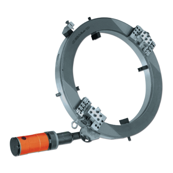
SECCION 3 ESPECIFICACIONES DE LA MÁQUINA 3.1 PRINCIPIO DE TRABAJO Las máquinas para corte y biselado de tubos son fijadas mediante ektexine por las pinzas en el anillo estacionario. Adopta el Motor Eléctrico para conducir el anillo a rotar, lo que hace que los dos postes de la herramienta roten alrededor de la tangente del tubo. -
Página 6: Rango De Operación Y Bloqueo Por Dilatación
4.2 RANGO DE OPERACIÓN Y BLOQUEO POR DILATACIÓN SISTEMA MÉTRICO 55815 55816 55817 55818 55819 55820 55821 55822 55823 55824 55825 55826 55827 55828 55829 55830 55831 55832 Model -150 -300 -450 -600 -750 -900 -1050 -1300 (mm) (mm) (mm) -
Página 7: Tablas De Tolerancias Axial Y Radial
4.4 TABLAS DE TOLERANCIAS AXIAL Y RADIAL NORMA MÉTRICA 55815 55816 55817 55818 55819 55820 55821 55822 55823 Model 55824 55825 55826 55827 55828 55829 55830 55831 55832 Standard -150 -300 -450 -600 -750 -900 -1050 -1300 “A” DIM (mm) -
Página 8: Instalación Y Procedimientos De Trabajo
DESLIZADO DE LA HERRAMIENTA Nuestros productos tienen el deslizamiento estándar de un nivel. BLOQUEO DE HINCHAMIENTO Parte necesaria para el proceso de corte y biselado de diferentes tipos y tamaños de tubos. UNIDAD MOTRIZ Motor eléctrico HERRAMIENTAS DE MANO Cada máquina de corte y biselado es suministrada con herramientas de mano(incluyendo cuchillas) para el ajuste y la operación. - Página 9 Precaución: asegúrese de que todos los tornillos circulares de cierre están apretados antes de continuar el proceso de instalación. 13. Ajuste el bloqueo de hinchamiento fijado apuntando a la posición 12 en punto o cerca de 12 en punto. Apriete el perno fijado del bloqueo de hinchamiento para hacerlo equivalente a la distancia del ordenador central a la parte superior e inferior de los tubos.
-
Página 10: Sección 6
Precaución: preocúpese por los tubos que caen al cortar piezas de largas. 29. Después de completar el corte, afloje el gatillo del motor o apague la electricidad, y desmantele el proceso. Precaución: Después de mecanizar, asegúrese de que la máquina está limpia, no hay residuos metálicos, no queda refrigerante en el almacenamiento de la máquina. -
Página 11: Sección 8
SECCION 8 PROBLEMAS Y SOLUCIONES Problema Posible Causa Solución Cable de alimentación o Comprobar cable de alimentación La máquina no funciona suministro de aire no o suministro de aire conectado Pieza de trabajo se desplaza Comprobar tensión en el mango Aflojamiento de abrazadera fijada durante operaciones de corte de la abrazadera fijada... - Página 12 ENGLISH TABLE OF CONTENTS Section 1 ............................13 Prelogue ..........................13 Section 2 ............................13 Safety instructions ........................13 Section 3 ............................15 Machine specifications ......................15 3.1 Working principle ......................15 3.2 Application range ......................15 3.3 Operating features ......................15 3.4 Package details ......................15 Section 4 ............................15 Technical specifications ......................15 4.1 Electric pipe cutting and beveling machine ..............15 4.2 Working range and swelling block ..................16...
-
Página 13: Section 1
SECTION 1 PRELOGUE Thanks for purchasing our pipe cutting and beveling machines. This instruction introduces the principle, instruction, function, technical specifications, delivery and installation, operation methods and safety instructions. Please read the instruction before using the equipment for correct installation and use. SECTION 2 SAFETY INSTRUCTIONS Our Company takes great pride in manufacturing safe, quality products with user safety apriority. - Página 14 Focus on operating equipment. The operator should careful about the process. If sick or tire, stop operating. Check whether the equipment is damaged. Before using equipment, check all the parts to ensure the function of the equipment. Check the parallelism or the working parts, lockpin of the rotating parts, damage of parts and the possible influence conditions caused.
-
Página 15: Section 3
SECTION 3 MACHINE SPECIFICATIONS 3.1 WORKING PRINCIPLE Pipe Cutting and Beveling Machines are fixed the ektexine of the pipes by the clamps on the Stationary Ring. It adopts Electric Motor to drive the ring rotate, which makes two tool posts rotate around the pipe tangent. -
Página 16: Working Range And Swelling Block
4.2 WORKING RANGE AND SWELLING BLOCK CHARTS METRIC SYSTEM 55815 55816 55817 55818 55819 55820 55821 55822 55823 55824 55825 55826 55827 55828 55829 55830 55831 55832 Model -150 -300 -450 -600 -750 -900 -1050 -1300 (mm) (mm) (mm) (mm) -
Página 17: Axial And Radial Clearance Charts
4.4 AXIAL AND RADIAL CLEARANCE CHARTS METRIC STANDARS 55815 55816 55817 55818 55819 55820 55821 55822 55823 Model 55824 55825 55826 55827 55828 55829 55830 55831 55832 Standard -150 -300 -450 -600 -750 -900 -1050 -1300 “A” DIM (mm) 1060 1306 “B”... -
Página 18: Installation And Working Procedures
make it easier to be connected to the pipes. The mainframe has been preset and adjusted by the factory. TOOL SLIDE Our products standard tool slide of one level. SWELLING BLOCK Necessary part for cutting and beveling process of different types and sizes pipes. DRIVING MOTOR Electric motor HAND TOOLS... - Página 19 12. After the mainframe is firmly installed on the pipes, take away circular Lock Pin. Caution: make sure all the circular Lock Screw tightened before continuing the installing process. 13. Adjust the fixed Swelling Block pointed to the position of 12 o’clock or close to 12’clock. Tighten fixed bolt of Swelling Block to make it equivalent that the distance from the mainframe to the top and the bottom of the pipes.
-
Página 20: Section 6
SECTION 6 MAINTENANCE AND REPAIR Maintenance and repair must be operated by proficient technician. To guarantee the machine to work well, original parts and accessories are preferable. Caution: before equipment maintenance, make sure the power is cut off. Keep original package well to transport equipments and accessories conveniently and promptly. Keep the equipment clean to make the equipment work on the optimal condition. - Página 21 If a problem persists or is not listed in the above table, please cease operation and consult the manufacturer for additional instruction. NOTES IMPORTANT! The maker will not take responsibility for damage or malfunction as a result of the machine being incorrectly used or, applied for a purpose for which it was not intended.
- Página 23 TO FULFILL THIS DOCUMENT AND RESEND IT TO EGA MASTER WITHIN 7 DAYS FROM SALE DATE. EGA MASTER GARANTIE A L’ACHETEUR DE CETTE MACHINE LA GARANTIE TOTALE (PENDANT 12 MOIS) DES PIECES AVEC DEFAUTS DE FABRICATION. CETTE GARANTIE NE COUVRE PAS LES PIECES QUE PAR UN USAGE NORMAL, SOIENT DETERIOREES.
- Página 26 C/ ZORROLLETA 11, POL. IND. JUNDIZ 01015 VITORIA, SPAIN P.O.B. APTDO. 5005 TEL. 34 - 945 290 001 FAX. 34 - 945 290 141 master@egamaster.com www.egamaster.com...