Tabla de contenido
Publicidad
Idiomas disponibles
Idiomas disponibles
Enlaces rápidos
Publicidad
Capítulos
Tabla de contenido
Solución de problemas

Manuales relacionados para cobas Urisys 1100


Resumen de contenidos para cobas Urisys 1100
- Página 1 Urisys 1100 Gebrauchsanweisung Operator’s Manual Manual de instrucciones...
- Página 2 Gebrauchsanweisung............ Seite 1–28 Operator’s Manual ............Page 29–54 Manual de instrucciones.......... Página 55–82...
- Página 4 Directive 98/79/EC on in vitro diagnostic la Directiva 98/79/CE sobre los produc- 98/79/EG. medical devices. tos sanitarios para diagnóstico in vitro. Stand der Information: Last update: Fecha de la última 2008-06 2008-06 revisión: 2008-06 COBAS, Urisys, Urisys 1100, Combur-Test and Reflotron are trademarks of Roche.
-
Página 5: Tabla De Contenido
Inhaltsverzeichnis Seite Einleitung Systembeschreibung Messprinzip Bedienungselemente und Funktion Software Übersicht Flussdiagramm des Benutzermenüs Funktionen des Benutzermenüs Ergebnistabelle Änderung der Bereichsgrenzen Inbetriebnahme Umrüstung auf Messung von Combur Test und Combur Test Teststreifen Benutzer-ID Authentifizierung Kalibration Teststreifenmessung Übersicht Normalmodus der Teststreifenmessung Ergebnisausdruck Schnellmodus (Serienmessung) Messfehler Eingeben einer Patienten-ID, Benutzer-ID und eines Authentifizierungspasswortes... -
Página 6: Einleitung
Test* von Roche Diagnostics. Die Teststreifen werden unter standardisierten Bedingungen gemessen, die Ergebnisse werden gespeichert und über den eingebauten Drucker oder die serielle Schnittstelle ausgegeben. Das Urisys 1100 System ist für die In-vitro-Diagnose (IVD) bestimmt und darf nur von sachkundigem Laborpersonal und Ärzten verwendet werden. -
Página 7: Systembeschreibung
Remissionswerte) wird das halbquantitative Konzentrationsergebnis (6) ermittelt. Die remissionsphotometrische Messung erfolgt für alle Parameter nach einer Inkubationszeit von ca. 55-65 Sekunden. Bei stark alkalischen Urinproben führt das Urisys 1100 System automatisch eine Korrektur des Messergebnisses des Testfeldes für das spezifische Gewicht (SG) durch. -
Página 8: Bedienungselemente Und Funktion
3. Software Übersicht Die Software des Urisys 1100 Systems beinhaltet eine Benutzerführung, bei der über Display-Anzeigen und Funktionstasten laborspezifische Grundeinstellungen und wiederkehrende Funktionen gewählt werden können (siehe Kapitel 3.2 und 3.3). Die Funktionen der 3 Funktionstasten beziehen sich jeweils auf die entsprechenden Stichworte in der zweiten Zeile des LCD- Displays, während die erste Zeile des Displays Statusanzeigen und andere Informationen für den Benutzer wiedergibt. -
Página 9: Flussdiagramm Des Benutzermenüs
Flussdiagramm des Benutzermenüs Bestätigung der Einstellung und Rückkehr in die Messbereitschaft aus jeder Menüebene mit der START-Taste. SW 5.x (Internationale Version) SELBST-TEST Ben.-ID=AN BENUTZER: ……. Ben.-ID eingeben! PASSWORD: Ben.-ID=AUS Passwort eingeben ! AUTH=AUS PASSWORD=O.K. Nr: … EINLEGEN ! Messbereitschaft Kalibr. Papier Menü KALIBRATION STARTEN! PAPIERVORSCHUB MENÜ... - Página 10 Flussdiagramm des Benutzermenüs (Fortsetzung) Bestätigung der Einstellung und Rückkehr in die Messbereitschaft aus jeder Menüebene mit der START-Taste. SW 5.x (Internationale Version) SETUP 1 Modus Streifen Setup 2 STREIFENEINSTELLUNGEN SETUP 2 Einheit Grenzen Datum/Zeit Par. Setup3 STREIFEN:CHEMSTRIP10 UX TT.MM.JJJJ hh:mm C-10 Sequenz 12/24...
-
Página 11: Funktionen Des Benutzermenüs
Funktionen des Benutzermenüs Selbsttest: Im Selbsttest prüft das Gerät nach dem Einschalten automatisch, ob der Program-Chip, der Antriebsmechanis- mus des Schlittens, der Druckeranschluss und die Optik einwandfrei funktionieren. Gleichzeitig wird geprüft, ob sich der eingelegte Schlitten in einwandfreiem Zustand befindet und dem im Menü ausgewählten Streifentyp entspricht (siehe Ka- pitel 4 und 7.1). - Página 12 Mit der Funktionstaste „Standard“ kann bei der Display-Anzeige „PARAMETERREIHENFOLGE“ die gewählte Selektion wieder rückgängig gemacht werden. Das Urisys 1100 System misst und speichert in jedem Falle alle Parameter des ver- wendeten Teststreifens. Falls nach den Messungen die Parameterselektion wieder auf die Standard-Einstellung zurückge- setzt wird, kann der vollständige Ergebnis bericht über das Menü...
- Página 13 Datum/Zeit: Einstellung von Datum und Uhrzeit. In der werkseitigen Einstellung wird das Datum in der Reihenfolge Tag-Monat-Jahr angezeigt, die Uhrzeit in Stunden (24- Stunden-Wechsel) und Minuten. Sofern erforderlich, kann die Uhrzeit auf einen 12-Stunden-Rhythmus (a.m./p.m.) umge- stellt werden. Über die Funktionstaste „Sequenz“ lässt sich das Datumsformat auf die Reihenfolge Monat-Tag-Jahr bzw. Jahr-Monat-Tag umstellen.
-
Página 14: Ergebnistabelle
Ergebnistabelle Das Urisys 1100 System druckt die Teststreifenergebnisse in folgenden Konzentrationsstufen aus: ACHTUNG: Genauere Informationen zum Verständnis der Messergebnisse finden Sie in der Roche- Publikation Compendium Urinalysis with Test Strips. Parameter Konventionelle Einheiten SI Einheiten Arbiträre Einheiten (Konv.) (SI) (Arbiträr) -
Página 15: Änderung Der Bereichsgrenzen
Änderung der Bereichsgrenzen Eine Änderung der Remissionsgrenzen ist innerhalb eines werkseitig begrenzten Bereichs für die unteren Konzentrations- stufen aller Teststreifenparameter mit Ausnahme von SG (Spezifisches Gewicht) und pH möglich. Zur Änderung der Remissionsgrenzen wird bei der Display-Anzeige „BEREICHSGRENZEN“ die linke Funktionstaste („Neu“) ge drückt. -
Página 16: Inbetriebnahme
Inbetriebnahme (1) Packen Sie das Urisys 1100 System aus und stellen Sie das Gerät auf eine feste, ebene Unterlage. Stellen Sie das Gerät nicht direkt in die Sonne oder unter eine andere direkte Lichtquelle (z.B. Lichtstrahler). Für Messungen mit dem Teststreifen Combur Test UX verwenden Sie den Teststreifenschlitten Typ „C“... - Página 17 (4) Schalten Sie das Urisys 1100 System mit dem Ein-/Aus-Schalter an der Geräterückseite ein. Selbsttest (5) Das Gerät führt automatisch einen Selbsttest durch. Das Urisys 1100 System ist werkseitig auf die Sprache „Englisch“ und auf die Messung von Combur Test UX Teststreifen eingestellt und erkennt, ob der passende Schlitten eingelegt wurde.
-
Página 18: Test Und Combur 5 Test Teststreifen
„N“ (Bestellnummer siehe Kapitel 11), der auf die Form der kürzeren Streifen zugeschnitten ist. Stellen Sie über das Menü den gewünschten Streifentyp ein. Nach der Bestätigung mit Hilfe der START-Taste legen Sie den Schlitten, Typ „N“, in das Gerät ein. Das Urisys 1100 System ist jetzt bereit für Messungen (siehe Kapitel 6). ACHTUNG: Combur Test und Combur Test Teststreifen besitzen kein Kompensationsfeld. -
Página 19: Kalibration
System mit Combur Test UX Teststreifen verwendet wird. Das Urisys 1100 System wurde bereits vor der Auslieferung werkseitig kalibriert. Der Kalibrationsvorgang muss bei der ersten Inbetriebnahme vor Beginn der Teststreifenmessungen und danach regelmäßig alle 7 Tage mit Hilfe des Kalibra- tionsstreifens Control-Test M wiederholt werden. -
Página 20: Teststreifenmessung
6. Teststreifenmessung Übersicht Die Bedienung des Urisys 1100 Systems ist äußerst einfach. Zur Messung von Harnteststreifen muss bei der Anzeige einer Probennummer lediglich ein Teststreifen aufgelegt und die START-Taste gedrückt werden, um mit der Messung zu begin- nen (siehe Kapitel 6.2). Das Gerät besitzt zwei unterschiedliche Betriebsarten zur Messung: 1. -
Página 21: Ergebnisausdruck
Solange eine Probennummer und „EINLEGEN!“ im Display angezeigt wird, ist das Urisys 1100 System bereit zur Messung. ACHTUNG: Bitte beachten Sie für die ordnungsgemäße Durchführung von Harnanalysemessungen auch die Hinweise in der Packungsbeilage der Harnteststreifen. 1. Teststreifen in die Urinprobe eintauchen, überschüssigen Urin vorsichtig abstreifen. Teststreifen kurz (ca. 1 Sek.) mit der seitlichen Kante auf einer saugenden Unterlage (z.B. -
Página 22: Messfehler
WARNHINWEIS: Bei der Durchführung von Serienmessungen im Schnellmodus ist unbedingt darauf zu achten, dass die Teststreifen bereits ca. 45 Sekunden reagiert haben, bevor sie in das Urisys 1100 System eingelegt werden und die START-Taste betätigt wird. Andernfalls ist damit zu rechnen, dass bei einigen Parametern zu niedrige oder falsch-negative Werte gemessen werden. -
Página 23: Datenübertragung An Einen Pc Oder Host-Rechner
ACHTUNG: Wenn während der Messung eines Teststreifens eine Pat. ID mit dem Barcodeleser eingelesen wird, ordnet das Urisys 1100 System diese ID der nächsten sequentiellen Probennummer zu. Eine Löschung dieser Pat. ID ist dann nur durch Aus- und Einschalten des Urisys 1100 Systems vor dem Start der nächsten Messung möglich. -
Página 24: Reinigung Und Wartung
5. Falls Sie gleich nach der Reinigung des Teststreifenschlittens noch weitere Messungen durchführen möchten, schalten Sie das Urisys 1100 System wieder ein. Warten Sie den Selbsttest des Gerätes ab, bei dem unter anderem geprüft wird, ob das Referenzfeld dem ordnungsgemäßen Ausgangszustand entspricht und der Positionierungskanal im Teststreifen- schlitten (Bild 17) durchgängig ist. -
Página 25: Fehlermeldungen Und Fehlerbeseitigung
Ursache: Der Program-Chip rechts unter der Druckerklappe (Bild 18) fehlt, hat keinen Kontakt, ist defekt oder enthält eine alte Software-Version. Maßnahme: Das Urisys 1100 System ausschalten. Program-Chip einsetzen und Gerät wieder einschalten. Wenn „CHIP ERROR!“ erneut angezeigt wird, liegt ein Gerätedefekt vor. - Página 26 E8 SCHLITTENPOS.-FEHLER ! Ursache: Positionierungskanal im Schlitten (Bild 17) verschmutzt oder nach Rei- nigung noch nass. Niederhaltebügel ist beim Herausfahren des Schlittens ge- öffnet, oder der Niederhaltemechanismus ist durch Urinverkrustungen blockiert (siehe Kapitel 7.1). Maßnahme: Positionierungskanal reinigen, durchblasen oder trocknen (fussel- freies Tuch verwenden) um eine einwandfreie Durchlässigkeit zu gewährleisten.
-
Página 27: Schnittstellenbeschreibung
ANGEZEIGT WIRD 9. Schnittstellenbeschreibung Serielle Schnittstelle Das Urisys 1100 System verfügt an der Geräterückseite über eine serielle Schnittstelle, die die Verbindung zu einem Perso- nalcomputer oder zentralen Host-Rechner ermöglicht. Bei dieser Schnittstelle handelt es sich nicht um eine RS-232- Schnittstelle. -
Página 28: Barcodeleser, At/Pc-Tastatur
+ 5 V Barcodeleser Barcodeleser für den Einsatz mit dem Urisys 1100 System mit der Softwareversion 5.0 und höher müssen die folgenden Spezifikationen erfüllen: - Hochfrequenzstörungen, Klasse B gemäß EN 61326-1 - Anforderungen an die elektromagnetische Störfestigkeit für industrielle Standorte gemäß EN 61326-1 Es gibt einen empfohlenen Barcodeleser für allgemein gebräuchliche Barcodes, wie z.B. -
Página 29: Technische Informationen Und Hinweise
10. Technische Informationen und Hinweise 10.1 Technische Daten Maße: Breite: ca. 150 mm Tiefe: ca. 290 mm Höhe: ca. 95 mm Gewicht: < 0,8 kg Stromversorgung: Externes Netzteil, Modell SA 125A-0735U-S Primär: 100 – 240 V Wechselstrom, 50-60 Hz, 800 mA Ausgang: 7.5 V Gleichspannung, 3000 mA Polarität: –... -
Página 30: Garantie
Reparatur am geöffneten Gerät unter Spannung darf nicht durchgeführt werden. Wenn anzunehmen ist, dass ein gefahrloser Betrieb nicht mehr möglich ist, so ist das Gerät außer Betrieb zu set- zen und gegen unabsichtlichen Betrieb zu sichern. Das Urisys 1100 System darf nur von sachkundigem Personal bedient werden. -
Página 31: Bestell-Liste
Gerät und Zubehör sind wie folgt lieferbar: Bestellnummer (REF) 03 617 548 Inhalt: Urisys 1100 Gerät Externes Netzteil Modell SA 125A-0735U-S,100 V – 240 V, 50-60 Hz, Program-Chip, Test- streifenschlitten C und N, Druckerpapier, Gebrauchsanweisung, Kurzbedienungsanleitung, Netzkabel, Interaktive Schulungs-CD. 03 666 735 Teststreifenschlitten, Typ „C“, für Combur... -
Página 32: Stichwortverzeichnis
12. Stichwortverzeichnis Kapitel Kapitel Akust. Signal Menüstruktur Software 3.2, 3.3 Anzeige-Texte 3.2, 8. Messprinzip Messung durchführen 6.2, 6.4 Messwertspeicher Messwerte speichern Barcodeleser Bedienungselemente Bereichsgrenzen 3.3, 3.4, 3.5 Bereichsgrenzen ändern Netzspannung 10.1 Control-Test M 3.3, 5., 11. Papiervorschub 3.3, 4. Parameter im Ergebnisausdruck festlegen Parameter im Ergebnisausdruck, Reihenfolge festlegen Daten löschen... - Página 33 Table of Contents Page Introduction System Description Measuring Principle Components and Functions Software Overview Menu Structure (Flowchart) Menu Functions Results Table Changing the Range Limits Installation Modification for Combur Test and Combur Test Test Strips Operator ID Authentication Calibration Reading Test Strips Overview Normal Mode (for Single Readings) Patient Report...
-
Página 34: Introduction
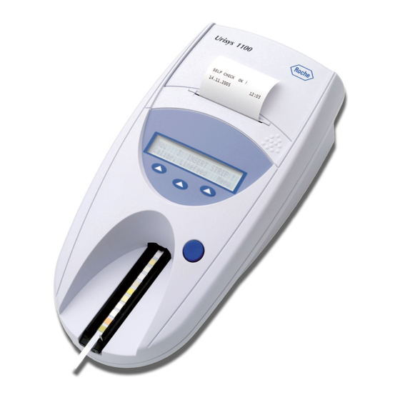
Amendments June 2008 Operator ID, limited lock-out function,Device ID, compatibility of barcode reader, ASTM protocol The Urisys 1100 system is a reflectance photometer designed to read and evaluate the urine test strips Combur Test UX, Combur Test and Combur Test* from Roche Diagnostics. It reads the strips under standard ized conditions, saves the results to memory and outputs them via its own inbuilt printer and/or serial interface. -
Página 35: System Description
Each test pad is read photometrically after a lead (incubation) time of about 55–65 seconds. In strongly alkaline urine sam- ples, the Urisys 1100 system automatically corrects the result of the Specific Gravity test. Gebrauchsanweisung V04 / Operator’s Manual V04 / Manual de instrucciones V04... -
Página 36: Components And Functions
3. Software Overview The Urisys 1100 system’s software provides a user interface that enables all laboratory-specific settings and recurrent func- tions to be selected via the liquid crystal display and function keys (see Sections 3.2 and 3.3). The three function keys assume the particular function displayed on the second line of the liquid crystal display. The first line of the display is used for system status and user information. -
Página 37: Menu Structure (Flowchart)
Menu Structure (Flowchart) Pressing the START button confirms the setting, closes the submenu, and resumes Ready-to-Measure status. SW 5.x (International Version) SELF CHECK Op.ID=ON OPERATOR: ……. Enter Op.ID! PASSWORD: Op.ID=OFF Enter password! AUTH.=OFF PASSWORD=O.K. No.: … INSERT STRIP ! Ready-to-Measure Status Calibr. - Página 38 Menu Structure (continued) Pressing the START button confirms the setting, closes the submenu, and resumes Ready-to-Measure status. SW 5.x (International Version) SETUP 1 Modes Strip Setup2 STRIP SETTINGS SETUP 2 Type Units Limits Date/Time Par. Setup3 STRIP TYPE:COMBUR10 UX DD.MM.YYYY hh:mm C-10 Sequence...
-
Página 39: Menu Functions
• Combur Test (“C-7”) • Combur Test (“C-5”) The Urisys 1100 system leaves our factory configured for Combur Test UX test strips. If you intend to use Combur Test or Combur Test test strips, you will require the appropriate test strip tray (see Sections 4.1 and 11). - Página 40 You can undo the selection by pressing the “Default” function key when the display shows “SEQUENCE PARAMETERS”. The Urisys 1100 system always measures and memorizes all of the parameters on whichever test strip is used. If, after reading, you wish to reset the choice of parameters to the standard setting, you can reinstate the complete report through the “MEMORY/Print”...
-
Página 41: Results Table
Results Table The Urisys 1100 system prints the results in the following gradation of concentration: ATTENTION: For full details on how to interpret results, consult the following Roche Diagnostics publication, Compendium Urinalysis with Test Strips. Parameter Conventional Units SI Units Arbitrary Units (Conv.) -
Página 42: Changing The Range Limits
4. Installation WARNING: Read the Urisys 1100 Operator’s Manual carefully before installation, so as to ensure proper operation of the analyzer from the outset. ATTENTION: If your analyzer has been exposed to marked changes in temperature and/or humidity, wait for it to acclimatize sufficiently before operating it. - Página 43 Instrument connection Power-on (1) Unpack the Urisys 1100 system and place it on a stable, level surface. Do not expose the analyzer to direct sunlight or other source of direct light (for example a spot lamp). For measurements of Combur Test UX test strips, the test strip tray with the type mark C on the reverse side is required.
-
Página 44: Test And Combur 5 Test Test Strips
Section 11), which exactly matches the geometry of the shorter test strips. Set the desired strip type from the menu. After pressing START to confirm, insert the Type “N” tray in the reader. The Urisys 1100 system is then ready (see Section 6). -
Página 45: Authentication
ATTENTION: If the maximum length of identification is exceeded the input cursor will skip to the first character and the identification will be overwritten. Authentication It is possible to download up to 300 operator IDs with corresponding passwords (up to 12 alphanumeric characters) from the host PC via the ASTM protocol. -
Página 46: Calibration
Test UX test strips. The Urisys 1100 system is calibrated before leaving the factory. When installed, it must be recalibrated with Control-Test M calibration strips before the first samples are read, and thereafter every seven days. Control-Test M calibration strips consist of a grey plastic material that is standardized to give constant, defined reflectance readings. -
Página 47: Reading Test Strips
Overview The Urisys 1100 system is very easy to use. Simply insert the test strip when the sample number is displayed (refer to Sec- tion 6.2), then press the START button to commence reading. The analyzer can be operated in two different modes: 1. -
Página 48: Patient Report
You can also perform serial readings provided that the strips are dipped and incubated for about 45 seconds outside the Urisys 1100 system. For this type of reading, “Fast Mode” should be selected from the menu. Place the test strips on the Urisys 1100 system tray after allowing them to incubate for approximately 45 seconds, pressing START to begin each read- ing. -
Página 49: Strip Measurement Error
1100 system assigns that ID to the next sample number in the sequence. The Patient ID can only be erased by switching the Urisys 1100 system off and then on again before starting the next reading. ATTENTION: If an identification will be entered and does exceed the maximum lengths of 13 characters for the patient Id or the 12 characters for the operator ID the cursor will move to the beginning (left side) of the display and delete the previously written characters. -
Página 50: Data Transmission To A Pc Or Host Computer
Press the keyboard ENTER key to terminate input, otherwise the Urisys 1100 system cannot start reading. Press the keyboard Escape key to delete the entire entry or turn the Urisys 1100 system off and then on again. -
Página 51: Error Messages And Troubleshooting
5. If you wish to proceed with the next readings directly after cleaning the test strip tray, switch the Urisys 1100 system on again. During the self check the system will verify that the reference pad is in good condition for reading and that the positioning hole in the test strip tray (see Figure 17) is free. - Página 52 (see Figure 18) is missing, is not making contact, is defective or contains an old soft ware version. Action: Switch off the Urisys 1100 system. Insert the program chip and switch the instrument on again. If “CHIP ERROR” appears again, the instrument is defective.
- Página 53 THE ANALYZER WILL Action: If an AT/PC keyboard is connected, press the Escape key, or switch NOT READ EVEN THOUGH THE the Urisys 1100 system off and back on again. SEQUENCE NUMBER IS DISPLAYED Gebrauchsanweisung V04 / Operator’s Manual V04 / Manual de instrucciones V04...
-
Página 54: Connecting To Other Devices
9. Connecting to Other Devices Serial Interface At the rear, the Urisys 1100 system has a serial interface through which it can be connected to a PC or central host compu- ter. This is not an RS 232 type interface. -
Página 55: Technical Information And Notices
Barcode Reader Barcode readers suitable for use with Urisys 1100 with SW Version 5.0 and above must meet the following specifications: - Radio frequency interference class B according to EN 61326-1 - Electromagnetic interference immunity requirements for industrial locations according to EN 61326-1 There is a recommended barcode reader to read commonly used barcodes such as Codabar, Code 39, Code 128 and Interleaved 2 of 5. -
Página 56: Safety Notices
If you suspect that the instrument can no longer be operated safely, turn it off and take steps to ensure that no one will subse quently attempt to use it. Make sure that only trained members of staff operate the Urisys 1100 analyzer. -
Página 57: Ordering Information
Test UX test strips 03 666 913 Test strip tray Type N for Combur Test/Combur Test test strips 03 617 572 Urisys 1100 Operator’s Manual 11 544 373 Combur Test UX (100 test strips) 11 008 552 Combur Test (100 test strips) -
Página 58: Alphabetical Index
12. Alphabetical Index Section Section Acoustic signal (beep) Operating parts Barcode reader Parameters in patient report, setup Basic settings Pat. Id. entry Beep (acoustic signal) Patient identification Positioning hole Positioning of test strip Power supply 4.,10.1 Cable configuration Printer paper Calibration 4., 4.1, 5. - Página 59 Indice Página Introducción Descripción del sistema Principio de medición Componentes y funciones Software Resumen Estructura del menú (diagrama) Funciones del menú Tabla de resultados Modificación de los rangos Puesta en marcha Cambio a la medición de las tiras reactivas Combur Test o Combur Test Código de identificación del operador...
-
Página 60: Introducción
ASTM El sistema Urisys 1100 es un fotómetro de reflexión destinado a la lectura y evaluación de tiras reactivas de orina Combur- Test UX, Combur Test y Combur Test* de Roche Diagnostics. -
Página 61: Descripción Del Sistema
Cada zona reactiva es leída fotométricamente después de un periodo de avance (incubación) de aproximadamente 55 – 65 segun dos. En muestras de orina fuertemente alcalinas, el sistema Urisys 1100 corrige automáticamente el resultado del test de gravedad específi ca (SG). -
Página 62: Componentes Y Funciones
Resumen El software del sistema Urisys 1100 incluye un interfaz de usuario con el que es posible seleccionar todos los ajustes básicos para el laboratorio y funciones recurrentes por medio de la pantalla de cristal líquido y teclas de función (ver los apartados 3.2 y 3.3). -
Página 63: Estructura Del Menú (Diagrama)
Estructura del menú (diagrama) Pulsando la tecla START, Vd. confirma el ajuste, cierra el submenú y retorna al estado “Listo para medición”. SW 5.x (Versión internacional) AUTOCONTROL Cod. Op.=ON OPERADOR: ……. Entrar nuevo COD. OP.! PASSWORD: Cod. Op.=OFF Entrar password ! AUTH=OFF PASSWORD=O.K. - Página 64 Estructura del menú (Continuación) Pulsando la tecla START, Vd. confirma el ajuste, cierra el submenú y retorna al estado “Listo para medición”. SW 5x (Versión internacional) SETUP 1 Modo Tira Setup2 AJUSTES DE TIRA SETUP 2 Tipo Unidad Limites Fecha/Hora Par.
-
Página 65: Funciones Del Menú
Funciones del menú Autocontrol: Tras el encendido, el aparato prueba mediante un autocontrol automático que el chip de programa, el meca- nismo de accionamiento de la guía, la conexión de impresora y el sistema óptico funcionan perfectamente. Al mismo tiem- po se comprueba el tipo de guía (ver apartados 4 y 7.1) para garantizar que se corresponde con el tipo de tiras selecciona- das en el menú. - Página 66 Con la tecla de función “Estándar” se puede anular la selección realizada cuando en la pantalla aparece el mensaje “SECUENCIA PARÁMETROS”. El sistema Urisys 1100 siempre mide y guarda todos los parámetros de la tira reactiva em- pleada. Si después de realizar la medición desea volver a ajustar la selección de parámetros en el ajuste estándar, puede volver a obtener el resultado de informe completo por medio del menú...
- Página 67 Fecha/hora: Ajuste de fecha y hora. El aparato ha sido ajustado en fábrica siguiendo el orden día-mes-año, y la hora en horas y minutos (conforme a periodos de 24 horas). No obstante, la hora también puede ser mostrada siguiendo el sistema “12 horas más a.m./p.m”. Pulse la te- cla de función “Secuencia”...
-
Página 68: Tabla De Resultados
Tabla de resultados El sistema Urisys 1100 imprime los resultados en los niveles de concentración siguientes: ATENCIÓN: Para obtener más detalles sobre cómo interpretar los resultados, consulte el siguiente folleto de Roche Diagnostics: Compendium Urinalysis with Test Strips. Parámetro Unidades convencionales... -
Página 69: Modificación De Los Rangos
4. Puesta en marcha ADVERTENCIA: Lea el Manual del Operador del sistema Urisys 1100 atentamente antes de proceder a la puesta en marcha para garantizar desde un principio la operación correcta del aparato. - Página 70 Puesta en marcha (1) Desembale el sistema Urisys 1100 y colóquelo sobre una superficie estable y plana. No lo exponga a la radiación solar directa ni lo coloque bajo otro tipo de foco luminoso (por ejemplo una lámpara). Para mediciones de tiras reactivas Combur Test UX se requiere la guía para tiras reactivas con la marca “C”...
-
Página 71: Cambio A La Medición De Las Tiras Reactivas Combur
(ver los apartados 3.2 y 3.3). (8) El sistema Urisys 1100 sale de fábrica con ajustes previos para impresora, medición y modos de interfaz, tipo de tiras reactivas, unidades, idioma, fecha/hora (ver apartado 3.2) y código de identificación del operador. Si su laboratorio acostumbra operar de otro modo, las preferencias individuales pueden ser introducidas a través de los menús. -
Página 72: Autenticación
ATENCIÓN: Si se supera la longitud máxima de identificación el cursor de entrada saltará al primer carác- ter y se sobreescribirá la identificación. Autenticación Es posible descargar hasta 300 códigos de identificación del operador con las respectivas contraseñas (hasta 12 caracte- res alfanuméricos) desde el servidor vía el protocolo ASTM. -
Página 73: Calibración
Test UX. El sistema Urisys 1100 ha sido previamente calibrado en fábrica. Una vez instalado, repita la calibración con tiras de cali- bración Control-Test M antes de llevar a cabo la primera medición, y posteriormente una vez por semana. Las tiras de cali- bración Control-Test M constan de material plástico gris estandardizado para suministrar mediciones de reflexión definidas... - Página 74 ATENCIÓN: Si contesta “No” a la invitación semanal “REPETIR CALIBRACIÓN”, por ejemplo porque ha consumido sus reservas de tiras de calibración Control-Test M, el mensaje “Repetir calibración” es impreso junto con cada informe de paciente de mediciones subsiguientes. Obtenga un nuevo paquete de Control-Test M y proceda inmediatamente a la recalibración.
-
Página 75: Medición De Las Tiras Reactivas
1. En el modo normal, el sistema Urisys 1100 observa automáticamente un periodo de reacción de 55 segundos antes de medir la primera zona reactiva. La medición concluye 70 segundos después de pulsar la tecla START, y la guía vuelve a la posición inicial. -
Página 76: Informe De Paciente
45 segundos fuera del aparato después de ser sumergidas en la muestra de orina. Elija a este fin la opción “Rápido” del menú. Pasados los 45 segundos puede introducir la tira reactiva en el sistema Urisys 1100 e iniciar la medición pulsan- do la tecla START. -
Página 77: Errores De Medición
Pulse la tecla ENTRAR para concluir la entrada de datos, de lo contrario el sistema Urisys 1100 no podrá iniciar la medición. Si precisa borrar la entrada por completo pulse la tecla ESCAPE del teclado o apague y vuelva a encender el sistema Urisys 1100. -
Página 78: Limpieza Y Mantenimiento
Limpieza y mantenimiento El sistema Urisys 1100 es un aparato diseñado para la operación libre de mantenimiento. Proteja el aparato de temperatu- ras extremas y niveles de humedad demasiado altos (ver apartado 10) así como de una radiación intensa de luz (luz solar directa u otros focos luminosos). -
Página 79: Mensajes De Error Y Solución De Problemas
5. Si desea efectuar mediciones inmediatamente después de la limpieza, encienda el sistema Urisys 1100 de nuevo. En el autocontrol, el sistema controla que la zona de referencia se encuentre en perfecto estado para iniciar la medición y que el canal de posicionamiento en la guía para tiras reacitvas (ver figura 17) no esté... - Página 80 (ver la figura 18) falta, no establece contacto, está defectuoso o contiene una versión de software antigua. Medida: Apague el sistema Urisys 1100. Introduzca el módulo chip y vuelva a en- cender el aparato. Si vuelve a aparecer “CHIP ERROR”, el instrumento está defec- tuoso.
- Página 81 NO ES POSIBLE INICIAR LA Medida: Si está conectado a un teclado AT/PC, pulse la tecla “Escape”, o apague MEDICIÓN AUNQUE EN LA el sistema Urisys 1100 y vuelva a encenderlo. PANTALLA APARECE UN NÚMERO CONSECUTIVO. Gebrauchsanweisung V04 / Operator’s Manual V04 / Manual de instrucciones V04...
-
Página 82: Conexión Con Otros Dispositivos
9. Conexión con otros dispositivos Interfaz serial El sistema Urisys 1100 dispone en su parte posterior de un interfaz serial que permite la conexión con un ordenador perso- nal o central. Este interfaz no es un tipo RS 232. Si lo desea, puede adquirir el cable de conexión correspondiente (ver también el apartado 11) de la casa Roche Diagnostics. -
Página 83: Datos Técnicos Y Advertencias
Lector de código de Barras Los lectores de código de barras adecuados para utilizar con Urisys 1100 con SW Versión 5.0 y superior deben satisfacer las especificaciones siguientes: - Interferencia de radiofrecuencia clase B según EN 61326-1 - Requisitos de inmunidad frente a interferencia electromagnética para emplazamientos industriales según EN 61326-1 Existe un lector de código de barras recomendado para leer códigos de barras utilizados frecuentemente como Codabar,... -
Página 84: Indicaciones De Seguridad
Desconecte el aparato y adopte las medidas necesarias para evitar una puesta en marcha accidental cuando pueda supo- nerse que no es posible un funcionamiento exento de peligro. El sistema Urisys 1100 sólo debe ser manejado por personal especializado. -
Página 85: Informaciones Para El Pedido
Test UX Tipo “C” 03 666 913 Guía para tiras reactivas Combur Test/Combur Test Tipo “N” 03 617 572 Manual de instrucciones Urisys 1100 11 544 373 Combur Test UX (100 tiras reactivas) 11 008 552 Combur Test (100 tiras reactivas) - Página 86 12. Registro alfabético Apartado Apartado Ajuste de la impresora Medición de tiras reactivas Ajuste del dato Memoria Ajustes de base Mensaje de pantalla 3.2, 8. Artículos de consumo y accesorios, pedir Mensajes de error Autocontrol Modo Standby Avance del papel 3.3, 4.
-
Página 87: Garantiekarte/Warranty Card/Certificado De Garantia
13. Garantiekarte/Warranty Card/Certificado de garantia Urisys 1100 Garantiekarte / Warranty Card Serien-Nr. Serial No. Name, Anschrift, Tel.-Nr. des Käufers Buyer’s name, address and tel. no. Kaufdatum: Stempel und Unterschrift des Händlers Date of purchase: Stamp and signature of dealer Urisys 1100 Certificado de garantía... -
Página 89: Adressenliste
14. Adressenliste/International addresses/Lista de direcciones Argentina Chile Productos Roche S.A.Q. e I. Productos Roche Ltda., División Diagnóstica Avda. Quilín 3750 Av. Belgrano 2350, Macul, Santiago Don Torcuato Buenos Aires Chile República Argentina Phone: +56 2 4413200 Phone: +54 11 5129-8000 Fax: +56 2 4626687 Fax: +54 11 5129-8105 China... - Página 90 Finland Indonesia Roche Oy Diagnostics PT Roche Indonesia Diagnostics Division PL 12, 02631 Espoo Artha Graha Building 21st Floor, Suomi Sudirman Central Business District – Lot 25, Phone: +358 9 525331 Jl. Jend. Sudirman Kav. 52 - 53 Fax: +358 9 52533351 12190 Jakarta Indonesia France...
- Página 91 New Zealand Portugal Roche Diagnostics N.Z. Ltd Roche Sistemas de Diagnósticos Lda. 15 Rakino Way, PO Box 62-089 Estrada Nacional, 249-1 Mt. Wellington, Auckland 2720-413 Amadora, New Zealand Portugal Phone: +64-9-276 4157 Phone: +351-21-417 1717 Fax: +64-9-276 5147 Fax: +351-21-417 1313 Norway Puerto Rico/Central America Roche Norge AS...
- Página 92 South Korea United Kingdom Roche Diagnostics Korea Co., Ltd Roche Diagnostics Ltd 15th Floor, Sam-Wha Building, 144/17, Samsung-dong, Charles Avenue Kangnam-Ku Burgess Hill, RH15 9RY 135-092 Seoul United Kingdom Republic of Korea Phone: +44 1444 256000 Phone: +82 2 550 3300 Uruguay Fax: +82 2 566 1878 Roche Diagnostics...
- Página 94 Roche Diagnostics GmbH D-68298 Mannheim Germany www.diavant.com www.roche-diagnostics.com...