Tabla de contenido
Publicidad
Idiomas disponibles
Idiomas disponibles
Enlaces rápidos
ATTACH YOUR RECEIPT HERE
Purchase Date
Questions, problems, missing parts? Before returning to your retailer, call our customer
service department at
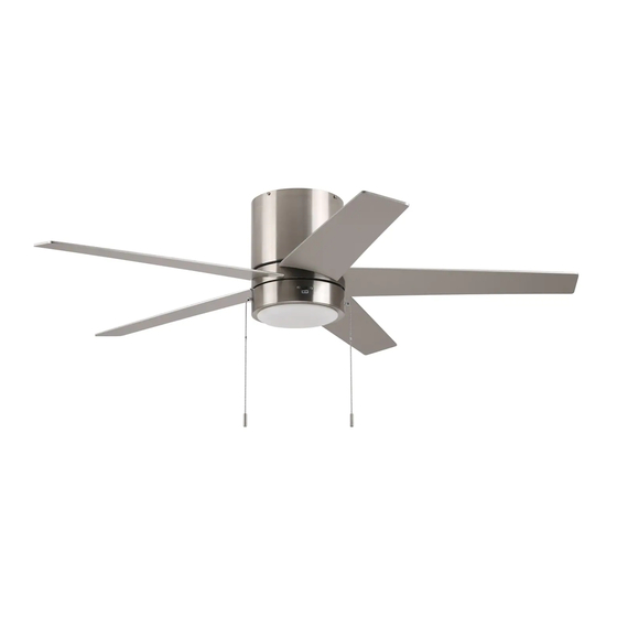
QUONTA LED CEILING FAN
1-800-527-1292, 8:30 a.m. - 5 p.m., CST, Monday - Friday.
1
ITEM
#2599766
2807160
2807161
MODEL
#CFH52BNK5L
CFH52MBK5L
CFH52WW5L
Español. 17
4007498
Publicidad
Capítulos
Tabla de contenido
Solución de problemas

Manuales relacionados para Harbor Breeze CFH52BNK5L


Resumen de contenidos para Harbor Breeze CFH52BNK5L
- Página 1 ITEM #2599766 2807160 2807161 QUONTA LED CEILING FAN MODEL #CFH52BNK5L CFH52MBK5L CFH52WW5L Español. 17 ATTACH YOUR RECEIPT HERE 4007498 Purchase Date Questions, problems, missing parts? Before returning to your retailer, call our customer service department at 1-800-527-1292, 8:30 a.m. - 5 p.m., CST, Monday - Friday.
-
Página 2: Tabla De Contenido
TABLE OF CONTENTS Safety Information ..........................2 Package Contents ..........................5 Hardware Contents ..........................6 Preparation ............................6 Initial Installation ..........................6 Wiring ..............................8 Final Installation ..........................10 Operating Instructions ........................13 Care and Maintenance ........................14 Troubleshooting..........................15 Limited Lifetime Warranty ........................16 Replacement Parts List ........................16 SAFETY INFORMATION Modifications not approved by the party responsible for compliance could void the user's authority to operate the equipment. - Página 3 SAFETY INFORMATION READ AND SAVE THESE INSTRUCTIONS Please read and understand this entire manual before attempting to assemble, install or operate the product. • Do not discard fan carton or foam inserts. Should this fan need to be returned to the factory for repairs, it must be shipped in its original packaging to ensure proper protection against damage that might exceed the initial cause for return.
- Página 4 SAFETY INFORMATION WARNING WARNING To reduce the risk of fire or electrical shock, do not use the fan with any solid state speed control device or control fan speed with a full range dimmer switch. To reduce the risk of fire, electrical shock or personal injury, do not bend the blades when installing or balancing them or cleaning the fan.
-
Página 5: Package Contents
PACKAGE CONTENTS PART DESCRIPTION PART DESCRIPTION QUANTITY QUANTITY Fitter Plate Screw Mounting Plate (preassembled to Fitter Motor Housing plate (C)) Fitter Plate Mounting Plate Screw LED Light Kit (preassembled to Mounting Shade Plate (A)) Blade Motor Plate Screw (preassembled to Motor Housing (B)) IMPORTANT REMINDER: You must use the parts provided with this fan for proper installation... -
Página 6: Hardware Contents
HARDWARE CONTENTS (shown actual size) Fiber Blade Blade Wire Washer Screw Connector Pull Chain Qty. 15 Qty. 15 Qty. 4 Extension + 1 extra + 1 extra Qty. 2 PREPARATION Before beginning assembly of product, make sure all parts are present. Compare parts with package contents list and hardware contents list. - Página 7 INITIAL INSTALLATION This fan can be mounted as a flushmount on a regular (no-slope) ceiling only. Check to make sure blades (F) will be at least 30 in. 30 in. from any obstruction and at least 7 ft. above min. the floor.
-
Página 8: Wiring
INITIAL INSTALLATION 5. Lift motor housing (B) to mounting plate (A) and then hang motor housing (B) on J-hook on J-Hook underside of mounting plate (A). (Use one of the non-slotted holes on the rim of the motor housing (B) to do so.) This will allow motor housing (B) to hang out of the way while wiring. - Página 9 WIRING FAN CONTROLLED BY PULL CHAIN, LIGHT BY WALL SWITCH 1b. FAN CONTROLLED BY PULL CHAIN, LIGHT BY WALL SWITCH: Connect BLACK wire from fan to BLACK wire from ceiling. Connect BLUE wire 120V POWER from fan to the BLACK wire from the independent FROM CEILING BLACK (POWER) wall switch for the light.
-
Página 10: Final Installation
FINAL INSTALLATION 1. Remove motor housing (B) from J-hook. Lift motor housing (B) to mounting plate (A). Align slotted holes on top rim of motor housing (B) with Slotted loosened mounting plate screws (I) in mounting Hole plate (A). Twist motor housing (B) to lock. Re-insert the two mounting plate screws (I) previously removed (step 3, page 7) and then tighten all four mounting plate screws (I) to... - Página 11 FINAL INSTALLATION Remove one preassembled fitter plate screw (H) from underside of fitter plate (C) and partially loosen the other two fitter plate screws (H). Connect WHITE molex wire from LED light kit (D) to WHITE molex wire from fitter plate (C). Connect BLUE molex wire from LED light kit (D) to BLACK (or BLUE) molex wire from fitter plate (C).
- Página 12 FINAL INSTALLATION Carefully arrange wires in center of fitter plate (C). Align slotted holes in edge of LED light kit (D) with loosened fitter plate screws (H) on fitter plate (C). Re-insert the other fitter plate screw (H) previously removed. Tighten all three fitter plate screws (H) securely.
-
Página 13: Operating Instructions
OPERATING INSTRUCTIONS The fan pull chain, located to the right of the reverse switch, has four positions to control fan speed. One pull is HIGH, two is MEDIUM, three is LOW and four turns the fan OFF. Reverse Switch The light pull chain, located to the left of the reverse switch, is used to turn the light ON or OFF. -
Página 14: Care And Maintenance
OPERATING INSTRUCTIONS 3a. In warmer weather, setting the reverse switch in the LEFT position will result in downward airflow creating a wind chill effect. 3b. In cooler weather, setting the reverse switch in the RIGHT position will result in upward airflow that can help move stagnant, hot air off the ceiling area. -
Página 15: Troubleshooting
TROUBLESHOOTING WARNING: Before beginning work, shut off the power supply to avoid electrical shock. PROBLEM POSSIBLE CAUSE CORRECTIVE ACTION Fan does not move. 1. Reverse switch not engaged. 1. Push switch firmly either left or right. 2. Power is off or fuse is blown. 2. -
Página 16: Limited Lifetime Warranty
LIMITED LIFETIME WARRANTY The distributor warrants this fan to be free from defects in workmanship and materials present at time of shipment from the factory for Lifetime limited from the date of purchase. This warranty applies only to the original purchaser. The distributor agrees to correct any defect at no charge or, at our option, replace the ceiling fan with a comparable or superior model. -
Página 17: Adjunte Su Recibo Aquí
ARTÍCULO #2599766 2807160 2807161 VENTILADOR DE TECHO QUONTA MODELO #CFH52BNK5L CFH52MBK5L CFH52WW5L ADJUNTE SU RECIBO AQUÍ 4007498 Fecha de compra ¿Preguntas, problemas, piezas faltantes? Antes de volver a la tienda, llame a nuestro Departamento de Servicio al Cliente al 1-800-527-1292, de lunes a viernes de 8:30 a.m. a... -
Página 18: Información De Seguridad
ÍNDICE Información de seguridad ........................18 Contenido del paquete ........................21 Lista de aditamentos ...........................22 Preparación ............................22 Instalación inicial ..........................22 Cableado .............................24 Instalación final.............................26 Instrucciones de funcionamiento ......................29 Cuidado y mantenimiento ........................30 Solución de problemas ........................31 Garantía limitada de por vida ......................32 Lista de piezas de repuesto .........................32 INFORMACIÓN DE SEGURIDAD Las modificaciones que no estén aprobadas por la parte responsable del cumplimiento podrían... - Página 19 INFORMACIÓN DE SEGURIDAD LEA Y GUARDE ESTAS INSTRUCCIONES Lea y comprenda completamente este manual antes de intentar ensamblar, instalar o usar el producto. • No deseche la caja del ventilador ni los accesorios de espuma. En caso de que deba devolver este ventilador a la fábrica para realizarle reparaciones, se debe enviar en su embalaje original para asegurar una protección adecuada contra daños que puedan aumentar la causa inicial de la devolución.
- Página 20 INFORMACIÓN DE SEGURIDAD ADVERTENCIA Para evitar lesiones personales, puede ser necesario usar guantes al manipular las piezas del ventilador con bordes filosos. Para reducir el riesgo de incendios o descargas eléctricas, no use el ventilador con dispositivos de control de velocidad para ventiladores de estado sólido ni controle la velocidad del ventilador con un regulador de intensidad de rango completo.
-
Página 21: Contenido Del Paquete
CONTENIDO DEL PAQUETE PIEZA DESCRIPCIÓN CANTIDAD PIEZA DESCRIPCIÓN CANTIDAD Placa de montaje Tornillo de la placa de soporte (preensamblado a Carcasa del motor la placa de soporte (C)) Placa de soporte Tornillo de la placa de Kit de iluminación LED montaje (preensamblado a Pantalla la placa de montaje (A)) -
Página 22: Lista De Aditamentos
ADITAMENTOS (se muestran en tamaño real) Arandela para Tornillo Conector aspa de fibra para aspa de cables Extensión para la Cant. 15 Cant. 15 Cant. 4 cadena de tiro más 1 más 1 adicional adicional Cant. 2 PREPARACIÓN Antes de comenzar a ensamblar el producto, asegúrese de tener todas las piezas. Compare las piezas con la lista del contenido del paquete y la lista de aditamentos. - Página 23 INSTALACIÓN INICIAL Este ventilador se puede colocar únicamente al ras en un techo regular (sin pendientes). Asegúrese de que las aspas (F) se encuentren 76,2 cm al menos a 76,2 cm de distancia de cualquier mín. tipo de obstrucción y al menos a 2,13 m del piso. 2,13 m mín.
-
Página 24: Cableado
INSTALACIÓN INICIAL Levante la carcasa del motor (B) hacia la placa de montaje (A) y cuelgue la carcasa del motor (B) en Gancho en el gancho en forma de J que se encuentra en la forma de J parte inferior de la placa de montaje (A). [Use uno de los orificios sin ranuras del reborde del ensamble del motor (B) para hacerlo]. -
Página 25: Cadena De Tiro Y Luz Controlada Por Interruptor De Pared
CABLEADO 1b. VENTILADOR CONTROLADO POR VENTILADOR CONTROLADO POR CADENA DE TIRO Y LUZ CONTROLADA POR INTERRUPTOR DE PARED CADENA DE TIRO Y LUZ CONTROLADA POR INTERRUPTOR DE PARED: conecte el cable NEGRO del ventilador al cable NEGRO del techo. ALIMENTACIÓN DE 120 V DESDE Conecte el cable AZUL del ventilador al cable EL TECHO... -
Página 26: Instalación Final
INSTALACIÓN FINAL Retire la carcasa del motor (B) del gancho en forma de J y deslice la parte superior de la carcasa del motor (B) sobre la placa de montaje (A) de manera que los orificios ranurados de la carcasa del motor Orificio Gancho ranurado... - Página 27 INSTALACIÓN FINAL 4. Retire un tornillo de la placa de soporte (H) de la placa de soporte (C) y afloje parcialmente los otros dos tornillos de la placa de soporte (H). Conecte el cable BLANCO del kit de iluminación LED (D) con el cable BLANCO de la placa de soporte (C).
- Página 28 INSTALACIÓN FINAL Ordene los cables en el centro de la placa de soporte (C) con cuidado. Alinee los orificios ranurados del kit de iluminación LED (D) con los tornillos aflojados de la placa de soporte (H) en la placa de soporte (C). Vuelva a insertar el tornillo de la placa de soporte (H) que retiró...
-
Página 29: Instrucciones De Funcionamiento
INSTRUCCIONES DE FUNCIONAMIENTO La cadena de tiro del ventilador, ubicada a la derecha del interruptor de reversa, tiene cuatro posiciones para controlar la velocidad del ventilador. Un movimiento activa la velocidad ALTA; dos para la velocidad MEDIA; tres para la velocidad BAJA;... -
Página 30: Cuidado Y Mantenimiento
INSTALACIÓN FINAL 3a. En climas más cálidos, configurar el interruptor de reversa en la posición a la IZQUIERDA creará un flujo de aire descendente que generará un efecto de viento refrescante. 3b. En climas más fríos, configurar el interruptor de reversa en la posición a la DERECHA creará un flujo de aire ascendente que puede ayudar a mover el aire caliente estancado para que salga del área del techo. -
Página 31: Solución De Problemas
SOLUCIÓN DE PROBLEMAS ADVERTENCIA: antes de comenzar cualquier trabajo, desconecte el suministro de electricidad para evitar descargas eléctricas. PROBLEMA CAUSA POSIBLE ACCIÓN CORRECTIVA El ventilador 1. El interruptor de reversa no está 1. Mueva el interruptor hacia la no se mueve. activado. -
Página 32: Garantía Limitada De Por Vida
GARANTÍA LIMITADA DE POR VIDA El distribuidor garantiza que este ventilador no presenta defectos en la mano de obra ni en los materiales presentes al momento del transporte desde la fábrica durante un período limitado de por vida a partir de la fecha de compra. Esta garantía es válida solo para el comprador original. El distribuidor acepta reparar cualquier defecto sin cargo o, según nuestro criterio, remplazar el ventilador de techo por un modelo comparable o superior.