Tabla de contenido
Publicidad
Idiomas disponibles
Idiomas disponibles
Enlaces rápidos
Harbor Breeze® is a registered trademark of
LF, LLC. All Rights Reserved.
ATTACH YOUR RECEIPT HERE
Serial Number
Questions, problems, missing parts? Before returning to your retailer, call or contact our
customer service department at 1-800-527-1292, 8:30 a.m. - 5:00 p.m., CST, Monday - Friday.
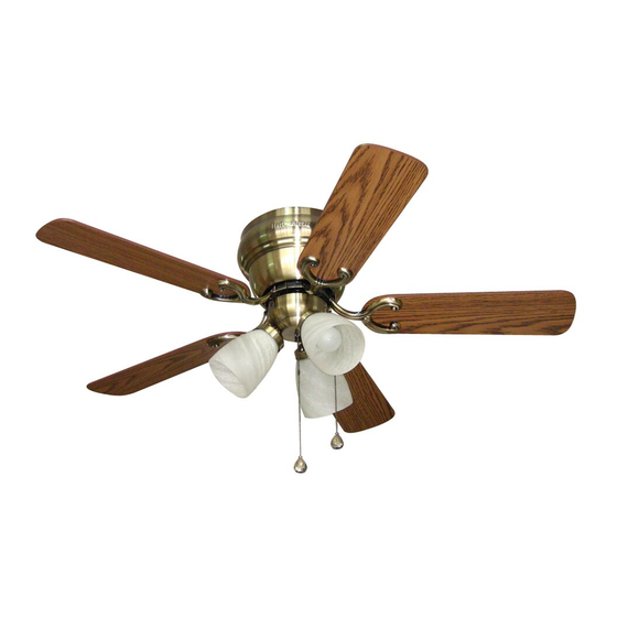
CHESHIRE II CEILING FAN
Purchase Date
1
ITEM #0317058
0317059
0317060
MODEL #CSD42AB5C3
CSD42BB5C3
CSD42LW5C3
Español p. 20
E124404
Publicidad
Capítulos
Tabla de contenido
Solución de problemas

Manuales relacionados para Harbor Breeze CSD42AB5C3


Resumen de contenidos para Harbor Breeze CSD42AB5C3
- Página 1 ITEM #0317058 0317059 0317060 CHESHIRE II CEILING FAN Harbor Breeze® is a registered trademark of LF, LLC. All Rights Reserved. MODEL #CSD42AB5C3 CSD42BB5C3 CSD42LW5C3 Español p. 20 ATTACH YOUR RECEIPT HERE Serial Number Purchase Date E124404 Questions, problems, missing parts? Before returning to your retailer, call or contact our...
-
Página 2: Tabla De Contenido
TABLE OF CONTENTS Safety Information ........………………………………………………...……..2 - 3 Product Overview ...........................4 Package Contents ..……………………………………………………………..….…....5 Hardware Contents .........................6 Preparation ....….…………………..……………………….…………….………………..6 Initial Installation ....….……………..……………………….……….…..…......7 - 8 Wiring .........……………………........………….....9 - 10 Final Installation ….…………….……………………….…………….……....…..11 - 14 Using Fan Without Light Kit (Optional) .................14 - 15 Operation Instructions ............……………………………....15 - 16 Care and Maintenance …….……………………………………………………..….....17... -
Página 3: Safety Information
SAFETY INFORMATION WARNINGS To reduce the risk of fire, electrical shock, or personal injury, mount fan to outlet box marked "ACCEPTABLE FOR FAN SUPPORT OF 35 LBS (15.9 KG) OR LESS" and use mounting screws provided with the outlet box. Most outlet boxes commonly used for the support of lighting fixtures are not acceptable for fan support and may need to be replaced. -
Página 4: Product Overview
Congratulations on your purchase of this Harbor Breeze® Ceiling Fan! This product has been specifically designed to give you all the performance you’ll ever need. Harbor Breeze® is the perfect fusion of smart innovation and beautiful style. Designed for more than just air movement, our products are built to function flawlessly... -
Página 5: Package Contents
PACKAGE CONTENTS PART DESCRIPTION QUANTITY PART DESCRIPTION QUANTITY Motor Housing Socket Ring (preassembled) Mounting Bracket Motor Screw Extra Switch Housing (preassembled) Motor Assembly Lock Washer Light Kit Fitter (preassembled) Glass Shade Motor Housing Mounting Blade Arm Screw (preassembled) Blade Mounting Bracket Flat Candelabra Base Bulb Washer (preassembled) Pull Chain Extension... -
Página 6: Hardware Contents
HARDWARE CONTENTS (shown actual size) Blade Fiber Screw Blade E3 Wire Washer Qty. 15 Connector Qty. 15 Qty. 4 PREPARATION Before beginning assembly of product, make sure all parts are present. Compare parts with package contents list and hardware contents above. If any part is missing or damaged, do not attempt to assemble the product. -
Página 7: Initial Installation
INITIAL INSTALLATION Turn off circuit breakers and wall switch to the fan supply line leads. (Fig. 1) DANGER: Failure to disconnect power supply prior to installation may result in serious injury or death. Check to make sure blades (H) will be at least 30 in. - Página 8 INITIAL INSTALLATION Secure mounting bracket (B) to outlet box using screws, spring washers, and flat washers provided with the outlet box. (Fig. 4) *Note: It is very important that you use the proper hardware when installing the mounting bracket (B) as this will support the fan. Remove motor screws (M) and lock washers (N) from underside of motor and save for blade arm (G) attachment later on.
-
Página 9: Wiring
WIRING WARNING: To reduce the risk of fire, electrical shock, or personal injury, wire connectors provided with this fan are designed to accept only one 12-gauge house wire and two lead wires from the fan. If your house wire is larger than 12-gauge or there is more than one house wire to connect to the two fan lead wires, consult an electrician for the proper size wire connectors to use. - Página 10 WIRING 1C. FAN AND LIGHT CONTROLLED BY TWO FAN AND LIGHT CONTROLLED BY TWO WALL SWITCHES WALL SWITCHES: If you intend to control the fan and light with separate wall switches, BLACK (WALL SWITCH) connect BLACK wire from fan to BLACK wire BLACK (WALL SWITCH FOR LIGHT) from the independent wall switch for the fan.
-
Página 11: Final Installation
FINAL INSTALLATION 1. Remove motor assembly (D) from "J" hook. Align holes in motor assembly (D) with holes in mounting bracket (B). Secure motor assembly (D) with mounting bracket flat washers (P) and mounting bracket nuts (K) that were previously removed (Step 3, page 7). - Página 12 FINAL INSTALLATION Locate motor screws (M) and lock washers (N) that were removed in Step 5 on page 8. Insert two motor screws (M), along with lock washers (N), through one blade arm (G) to attach blade arm (G) to motor. Tighten motor screws (M) securely.
- Página 13 FINAL INSTALLATION Gently push wires and molex connections into switch housing plate. Align fan pull chain slot with fan pull chain and attach light kit fitter (E) to fan with switch housing plate screws (R) that were Switch removed in the previous step. Use a Phillips Housing screwdriver (not included) to secure all three Plate...
-
Página 14: Using Fan Without Light Kit (Optional)
FINAL INSTALLATION The pull chain extensions (J) supplied in one of the hardware packs or custom pull chain extensions (not included) may be attached to fan and light pull chains. (Fig. 9) (For Fan) (For Light) USING FAN WITHOUT LIGHT KIT (OPTIONAL) If you do NOT wish to use the light kit, remove three switch housing plate screws (R). -
Página 15: Operation Instructions
USING FAN WITHOUT LIGHT KIT (OPTIONAL) The pull chain extension (J) supplied in one of the hardware packs or custom pull chain extension (not included) may be attached to fan. (Fig. 3) OPERATION INSTRUCTIONS The pull chain on the switch housing plate, which is inside the light kit fitter (E), has four positions to control fan speed. -
Página 16: Important
OPERATION INSTRUCTIONS Use the fan reverse switch, located on light kit fitter (E), to optimize your fan for seasonal performance. (Fig. 3) A ceiling fan will allow you to raise your thermostat setting in summer and lower your thermostat setting in winter without feeling a difference in your comfort. -
Página 17: Care And Maintenance
CARE AND MAINTENANCE At least twice each year, lower motor housing (A) to check motor assembly (D), and then tighten all screws on fan. Clean motor housing (A) with only a soft brush (not included) or lint-free cloth (not included) to avoid scratching the finish. Clean blades (H) with a lint-free cloth. You may occasionally apply a light coat of furniture polish (not included) to wood blades for added protection. -
Página 18: Troubleshooting
TROUBLESHOOTING PROBLEM POSSIBLE CAUSE CORRECTIVE ACTION 1. Bulb(s) not installed correctly. Fan operates but 1. Re-install bulb(s). 2. Wires in outlet box not wired properly. lights fail. 2. Check wires in outlet box, and if necessary, re-wire according to instructions on pages 8 and 9. 3. -
Página 19: Replacement Parts List
REPLACEMENT PARTS LIST For replacement parts, call our customer service department at 1-800-527-1292, 8:30 a.m.-5:00 p.m., CST, Monday-Friday. When ordering parts, please have the Model # or Item # of the fan available, which can be found on page 1. PART DESCRIPTION Motor Housing... -
Página 20: Adjunte Su Recibo Aquí
0317060 VENTILADOR DE TECHO ® Harbor Breeze es una marca registrada de LF, LLC. Todos los derechos reservados. CHESHIRE II MODELO #CSD42AB5C3 CSD42BB5C3 CSD42LW5C3 ADJUNTE SU RECIBO AQUÍ E124404 Fecha de compra Número de serie ¿Preguntas, problemas, piezas faltantes? Antes de volver a la tienda, llame a nuestro Departamento de Servicio al Cliente al 1-800-527-1292, de lunes a viernes de 8:30 a.m. -
Página 21: Indice De Materias
INDICE DE MATERIAS Información de seguridad ..……………………………………………......21 - 22 Descripción general del producto ....................23 Contenido de paquete ....………………………………………………………..24 Contenido de artículos de ferretería ....………………………………....... 25 Preparación .........................25 Instalación inicial ..........……………………………………....26 - 27 Conexión de los cables .........……………………………………..28 - 30 Instalación final ....……………….…………….…….………………….…....31 - 34 Uso del ventilador sin el juego de luz (opcional) ..............34 - 35... - Página 22 INFORMACIÓN DE SEGURIDAD ADVERTENCIAS Para reducir el riesgo de incendios, descargas eléctricas o lesiones personales, monte a una caja de salida marcada como "ACCEPTABLE FOR FAN SUPPORT OF 35 LBS (15.9 KG) OR LESS" (apta para sostener un ventilador de 15,88 kg (35 lb) o menos) y utilice los tornillos de montaje incluidos en la caja de salida.
-
Página 23: Descripción General Del Producto
LF, LLC. Todos los derechos reservados. Obtenga calidad de sala de exhibición a un precio excepcional ® con Harbor Breeze , disponible exclusivamente en Lowe's. Decidir cómo desea que luzca y funcione su ventilador de techo es un paso importante antes de la instalación. -
Página 24: Contenido Del Paquete
CONTENIDO DEL PAQUETE PIEZA DESCRIPCION CANTIDAD PIEZA DESCRIPCION CANTIDAD Bastidor del motor Anillo de portalámpara (preensamblado) Soporte de montaje Tornillo del motor Cubierta de la caja del (preensamblado) interruptor adicional Arandela de seguridad Unidad del motor (preensamblada) Conectador para el juego Tornillo del bastidor del de luz motor (preensamblado) -
Página 25: Contenido De Artículos De Ferretería
CONTENIDO DE ARTÍCULOS DE FERRETERÍA (se muestran en tamaño real) Arandela de Tornillo fibra para para paleta Conector de la paleta Cant. 15 cables E3 Cant. 15 Cant. 4 PREPARACIÓN Antes de comenzar a ensamblar el producto, asegúrese de tener todas las piezas. Compare las piezas con la lista del contenido del paquete y la lista de artículos de ferretería anteriores. -
Página 26: Instalación Inicial
INSTALACIÓN INICIAL Interrumpa el suministro de energía del ventilador apagando los interruptores de circuito y el interruptor de pared. (Fig. 1) PELIGRO: Si no interrumpe el suministro de electricidad antes de la instalación, pueden producirse lesiones graves o la muerte. Asegúrese de que las paletas (H) del ventilador quedarán a por lo menos 30 pulgadas (76,2 cm) de cualquier obstrucción y a por lo menos 7 pies... - Página 27 INSTALACIÓN INICIAL Asegure el soporte de montaje (B) a la caja de salida con los tornillos, las arandelas de resorte, y las arandelas planas provistos con la caja de salida. (Fig. 4) *Nota: Es muy importante usar los artículos de ferretería correctos al instalar el soporte de montaje (B) puesto que sirve para sostener el ventilador.
-
Página 28: Conexión De Los Cables
CONEXIÓN DE LOS CABLES ADVERTENCIA: Para reducir el riesgo de incendios, descargas eléctricas o lesiones personales, los conectores de cables incluidos con este ventilador están diseñados para soportar sólo un cable interior de calibre 12 y dos cables conductores del ventilador. Si el cable interior es de un calibre superior a 12 o hay más de un cable interior para conectar los dos cables conductores del... -
Página 29: Ventilador Controlado Por Cadena De Tiro Y Luz Controlada Por Interruptor De Pared
CONEXIÓN DE LOS CABLES VENTILADOR CONTROLADO POR CADENA DE TIRO 1B. VENTILADOR CONTROLADO POR Y LUZ CONTROLADA POR INTERRUPTOR DE PARED CADENA DE TIRO Y LUZ CONTROLADA POR INTERRUPTOR DE PARED: Si desea NEGRO controlar la luz del ventilador con un interruptor NEGRO (INTERRUPTOR DE PARED) Alimentación de 120 V... -
Página 30: Importante
CONEXIÓN DE LOS CABLES Envuelva con cinta aislante (no incluido) cada conector de cable (CC) individual hacia abajo del cable como se muestra en la Fig. 2. ADVERTENCIA: Asegúrese de que no haya conductores desnudos ni filamentos de conductores visibles después de hacer la conexión. -
Página 31: Instalación Final
INSTALACIÓN FINAL Quite la unidad del motor (D) del gancho en forma de "J". Alinee los agujeros en la unidad del motor (D) con los agujeros en el soporte de montaje (B). Asegure la unidad del motor (D) con las arandelas planas del soporte de montaje (P) y las tuercas del soporte de montaje (K) que se quitaron anteriormente (paso 3, página 25). - Página 32 INSTALACIÓN FINAL 3. Parcialmente introduzca tres tornillos para paleta (AA), junto con tres arandelas de fibra para la paleta (BB), para fijar el brazo de la paleta (G) a una paleta (H). Luego, apriete cada tornillo para paleta (AA), empezando con el de en medio.
- Página 33 INSTALACIÓN FINAL Si desea UTILIZAR el juego de luz, quite los tres tornillos de la placa de la caja del interruptor (R) del lado inferior del motor. Localice los cables AZUL y BLANCO en la lpaca de la caja del interruptor etiquetados "FOR LIGHT"...
-
Página 34: Uso Del Ventilador Sin El Juego De Luz (Opcional)
INSTALACIÓN FINAL Instale las tres bombillas de base candelabro (I) de 60 vatios incluidas. (Fig. 8) Importante: Cuando reemplace las bombillas, por favor permita que se enfríen las bombillas y las pantallas de vidrio antes de tocarlas. Se pueden fijar las extensiones para las cadenas de encendido (J) provistas en uno de los paquetes de artículos de ferretería a las cadenas de encendido para el ventilador y la luz o usar extensiones para... -
Página 35: Instrucciones De Funcionamiento
USO DEL VENTILADOR SIN EL JUEGO DE LUZ (OPCIONAL) Alinee los agujeros de la cubierta del interruptor adicional (C) con los agujeros en la placa de la caja del interruptor. (Nota: El espacio ancho en el borde superior de la caja del interruptor adicional placa de (C) debe alinearse con el interruptor de reversa en la caja del... - Página 36 INSTRUCCIONES DE FUNCIONAMIENTO La cadena de encendido localizada en el centro se usa para ENCENDER o APAGAR las luces. (Fig. 2) Use el interruptor de reversa, localizada en el conectador para el juego de luz (E), para optimizar el uso del ventilador durante las estaciones. (Fig. 3) Un ventilador de techo le permitirá...
-
Página 37: Cuidado Y Mantenimiento
FUNCIONAMIENTO DEL VENTILADOR IMPORTANTE: Hay que mover el interruptor de reversa o completamente hacia la DERECHA o completamente hacia la IZQUIERDA para que funcione el ventilador. Si el interruptor de reversa está puesto en la posición de en medio (Fig. 3C), no funcionará... -
Página 38: Solución De Problemas
SOLUCIÓN DE PROBLEMAS PROBLEMA CAUSA POSIBLE ACCIÓN CORRECTIVA 3. Reemplace por un dispositivo de 3. Se está utilizando un regulador de intensidad de rango completo. control de velocidad autorizado. 4. Permita unos días para que el 4. El ventilador es nuevo. motor del ventilador se equilibre, especialmente al usar el ventilador a velocidad media o alta. -
Página 39: Garantía
GARANTIA GARANTIA LIMITADA DE POR VIDA: Litex Industries garantiza que este ventilador está libre de defectos de mano de obra y de materiales desde la fecha de salida de la fábrica por el tiempo de por vida limitada a partir de la fecha de compra. Esta garantía sólo se aplica al comprador original. Litex Industries se compromete a corregir cualquier defecto libre de cargo o, si lo considera necesario, a reemplazar el ventilador por un modelo equiparable o superior. -
Página 40: Lista De Piezas De Repuestos
LISTA DE PIEZAS DE REPUESTOS Para piezas de repuesto, llame a nuestro departamento de servicio al cliente al 1-800-527-1292, de 8:30 a.m. a 5:00 p.m., hora central, de lunes a viernes. Al pedir piezas, por favor tenga listo el Nº. de modelo o Nº.