Tabla de contenido
Publicidad
Idiomas disponibles
Idiomas disponibles
Enlaces rápidos
Harbor Breeze® is a registered trademark of
LF, LLC. All Rights Reserved.
ATTACH YOUR RECEIPT HERE
Serial Number
Questions, problems, missing parts? Before returning to your retailer, call or contact our
customer service department at 1-800-527-1292, 8:30 a.m. - 5:00 p.m., CST, Monday - Friday.
Purchase Date
1
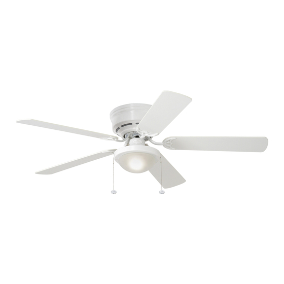
ARMITAGE CEILING FAN
MODEL #CC52WW5C
ITEM #0020776
Español p. 17
E124404
Publicidad
Capítulos
Tabla de contenido

Manuales relacionados para Harbor Breeze CC52WW5C


Resumen de contenidos para Harbor Breeze CC52WW5C
- Página 1 ITEM #0020776 ARMITAGE CEILING FAN MODEL #CC52WW5C Harbor Breeze® is a registered trademark of LF, LLC. All Rights Reserved. Español p. 17 ATTACH YOUR RECEIPT HERE Serial Number Purchase Date E124404 Questions, problems, missing parts? Before returning to your retailer, call or contact our...
-
Página 2: Tabla De Contenido
TABLE OF CONTENTS Safety Information ........………………………………………………...……..2 - 3 Package Contents ..……………………………………………………………..….….....4 Hardware Contents ........................5 Preparation ....….…………………..……………………….…………….………………..5 Initial Installation ....….……………..……………………….……….…..…......6 - 7 Wiring .........……………………........…………....7 - 9 Final Installation ….…………….……………………….…………….……....……9 - 12 Operation Instructions ............……………………………..12 - 13 Care and Maintenance …….……………………………………………………..…....13 Troubleshooting .....………...………………………….……………..………..…....14 Warranty ……………………………….…………………………………………..……....15... -
Página 3: Safety Information
SAFETY INFORMATION WARNINGS To reduce the risk of fire, electrical shock, or personal injury, mount fan to outlet box marked "ACCEPTABLE FOR FAN SUPPORT" and use mounting screws provided with the outlet box. Most outlet boxes commonly used for the support of lighting fixtures are not acceptable for fan support and may need to be replaced. -
Página 4: Package Contents
PACKAGE CONTENTS PART DESCRIPTION QUANTITY PART DESCRIPTION QUANTITY Mounting Bracket Mounting Bracket Flat Washer (preassembled) Shade Fitter Plate Mounting Bracket Nut Motor Housing (preassembled) Motor Assembly Lock Washer Glass Shade (preassembled) Blade Arm Motor Screw Blade (preassembled) Pull Chain Extension Motor Housing Mounting Candelabra Base Bulb Screw (preassembled) -
Página 5: Hardware Contents
HARDWARE CONTENTS (shown actual size) Blade Fiber Screw Blade E3 Wire Washer Connector Qty. 15 Qty. 15 Qty. 4 PREPARATION Before beginning assembly and installation of product, make sure all parts are present. Compare parts with “Package Contents” list and diagrams on the previous page. If any part is missing or damaged, do not attempt to assemble, the product. -
Página 6: Initial Installation
INITIAL INSTALLATION Turn off circuit breakers and wall switch to the fan supply line leads. (Fig. 1) DANGER: Failure to disconnect power supply prior to installation may result in serious injury or death. Check to make sure blades (G) are at least 30 in. from any obstruction and at least 7 ft. -
Página 7: Wiring
INITIAL INSTALLATION Remove motor screws (M) and lock washers (L) from underside of motor and save for blade arm (F) attachment later on. [If there are plastic motor blocks installed with the motor screws (M) and lock washers Motor (L), discard the plastic motor blocks.] (Fig. 5) Slide the slot in the bar at the top of the motor assembly (D) onto the "J"... - Página 8 WIRING Choose wiring diagram (Fig. 1A, Fig. 1B or Fig. 1C) FAN AND LIGHT CONTROLLED BY PULL CHAINS that fits your situation and make appropriate wiring connections as follows: [NOTE: For each wire BLACK connection below, use one of the wire connectors WHITE 120 V Power FROM...
-
Página 9: Final Installation
WIRING Wrap electrical tape around each individual wire connector (CC) down to the wire as shown in Fig. 2. WARNING: Make sure no bare wire or wire strands are visible after making connections. Place green and white connections on opposite side of box from the black and blue (if applicable) connections. - Página 10 FINAL INSTALLATION Temporarily lift motor housing (C) to mounting bracket (A) to determine which two motor housing mounting screws (N) in sides of mounting bracket (A) align with the slotted holes in the top edge of the motor housing (C) and partially loosen these two screws (N). Remove the other two screws (N) and motor housing lock washers (O) from sides of mounting bracket (A).
- Página 11 FINAL INSTALLATION Remove three screws and washers from center of shade fitter plate (B). Align notch in shade fitter plate (B) with small protrusion on the inside of the light kit plate. Secure shade fitter plate (B) with the three screws (and washers) that were just removed.
-
Página 12: Operation Instructions
FINAL INSTALLATION Pull chain extensions (H) supplied in the hardware packs or custom pull chain extensions (sold separately) may be attached to fan and light pull chains. (Fig. 8) OPERATION INSTRUCTIONS The pull chain located to the right of the reverse switch has four positions to control fan speed. -
Página 13: Important
OPERATION INSTRUCTIONS Use the fan reverse switch, located on the switch housing, to optimize your fan for seasonal performance. (Fig. 3) A ceiling fan will allow you to raise your thermostat setting in summer and lower your thermostat setting in winter without feeling a Switch difference in your comfort. -
Página 14: Troubleshooting
TROUBLESHOOTING If you have any questions regarding the product please call customer service at 1-800-527-1292, 8:30 a.m. - 5 p.m., CST, Monday - Friday. Warning: Before beginning work, shut off the power supply to avoid electrical shock. PROBLEM POSSIBLE CAUSE CORRECTIVE ACTION Fan does not move. -
Página 15: Warranty
WARRANTY LIMITED LIFETIME WARRANTY: Litex Industries warrants this fan to be free from defects in workmanship and materials present at time of shipment from the factory for Lifetime limited from the date of purchase. This warranty applies only to the original purchaser. Litex Industries agrees to correct any defect at no charge or, at our option, replace the ceiling fan with a comparable or superior model. -
Página 16: Replacement Parts List
REPLACEMENT PARTS LIST For replacement parts, call our customer service department at 1-800-527-1292, 8:30 a.m. - 5:00 p.m., CST, Monday-Friday. When ordering parts, please have the Model # or Item # of the fan available, which can be found on page 1. PART DESCRIPTION Mounting Bracket... -
Página 17: Ventilador De Techo Armitage
ARTICULO #0020776 VENTILADOR DE TECHO ARMITAGE MODELO #CC52WW5C Harbor Breeze® es marca registrada de LF, LLC. Reservados todos los derechos. ADJUNTE SU RECIBO AQUI E124404 Número de serie Fecha de compra ¿Preguntas, problemas, faltan piezas? Antes de regresar a la tienda, llame o póngase en contacto con nuestro departamento de servicio al cliente al 1-800-527-1292, de 8:30 a.m. -
Página 18: Indice De Materias
INDICE DE MATERIAS Información de seguridad ..……………………………………………....18 - 19 Contenido del paquete ....………………………………………………………..20 Contenido de artículos de ferretería ....………………………………....21 Preparación ..........….…………………..………………....21 Instalación inicial ..........……………………………………..22 - 23 Conexión de los cables .........…………………………………….23 - 25 Instalación final ....……………….…………….…….………………….…....25 - 28 Instrucciones de funcionamiento ....…..............28 - 29 Cuidado y mantenimiento... - Página 19 INFORMACION DE SEGURIDAD ADVERTENCIAS Para reducir el riesgo de incendio, choque eléctrico o daño corporal, sujete el ventilador a una caja de salida marcada "Aceptable para sostener ventilador" ("ACCEPTABLE FOR FAN SUPPORT" en inglés) y use los tornillos de montaje proporcionados con la caja de salida.
-
Página 20: Contenido Del Paquete
CONTENIDO DEL PAQUETE PIEZA DESCRIPCION CANTIDAD PIEZA DESCRIPCION CANTIDAD Soporte de montaje Arandela plana del soporte de montaje Placa de conexión para la (preensamblada) pantalla Tuerca del soporte de Bastidor del motor montaje (preensamblada) Unidad del motor Arandela de seguridad Pantalla de vidrio (preensamblada) Brazo para la paleta... -
Página 21: Contenido De Artículos De Ferretería
CONTENIDO DE ARTICULOS DE FERRETERIA (se muestra en tamaño natural) Arandela Tornillo de fibra para la Conector para la paleta para paleta cable E3 Ctd.15 Ctd.15 Ctd. 4 PREPARACION Antes de empezar con el ensamblaje e instalación del producto, asegúrese de tener todas las piezas. -
Página 22: Instalación Inicial
INSTALACION INICIAL Apague todos los disyuntores del circuito y el interruptor de pared a la línea de suministro de electricidad del ventilador. (Fig. 1) PELIGRO: El no desconectar el suministro de electricidad antes de la instalación puede resultar en daños graves o la muerte. Asegúrese de que las paletas (G) del ventilador queden a por lo menos 76,2 cm de cualquier obstrucción y a por lo menos 2,13 m arriba del nivel... -
Página 23: Conexión De Los Cables
INSTALACION INICIAL Saque los tornillos del motor (M) y las arandelas de seguridad (L) del lado inferior del motor y guárdelos para sujetar los brazos para las paletas (F) después. [Si se encuentran soportes de plástico instalados motor con los tornillos del motor (M) y las arandelas de seguridad (L), deseche los soportes de plástico.] (Fig. -
Página 24: Ventilador Controlado Por Cadena De Encendido, Luz Por Interruptor De Pared
CONEXION DE LOS CABLES Escoja el diagrama de instalación eléctrica (Fig. 1A, Fig. VENTILADOR Y LUZ CONTROLADOS POR CADENAS 1B o Fig. 1C) que corresponde a su situación y haga las conexiones apropiadas según lo que sigue: [NOTA: Para NEGRO 120 V cables BLANCO cada conexión de cable que se va a hacer a continuación,... -
Página 25: Importante
CONEXION DE LOS CABLES Ponga cinta aislante en cada conector para cable (CC) por separado como se muestra en la Fig. 2. Advertencia: Asegúrese de que no se vean cables pelados ni filamentos después de hacer las conexiones. Coloque las conexiones verdes y blancas en la caja al lado opuesto de las negras y azules (si aplica). - Página 26 INSTALACION FINAL Temporalmente levante el bastidor del motor (C) al soporte de montaje (A) para determinar cuáles tornillos para montaje del bastidor del motor (N) que se encuentran en las orillas del soporte de montaje (A) se alinean con los agujeros con ranura en el borde superior del bastidor del motor (C) y afloje dichos tornillos (N) parcialmente.
- Página 27 INSTALACION FINAL Quite tres tornillos y arandelas del centro de la placa de conexión para la pantalla (B). Alinee la muesca en la placa de conexión para la pantalla (B) con la protuberancia pequeña dentro de la placa del juego de luz. Asegure la placa de conexión para la placa del pantalla (B) con los tres tornillos (y arandelas) que juego de...
- Página 28 INSTALACION FINAL Se pueden fijar las extensiones para las cadenas de encendido (H) provistas en los paquetes de artículos de ferretería a las cadenas de encendido para el ventilador y la luz o usar extensiones para cadenas de encendido hechas a medida (a la venta por separado).
-
Página 29: Cuidado Y Mantenimiento
INSTRUCCIONES DE FUNCIONAMIENTO Use el interruptor de reversa, localizado en la caja del interruptor, para optimizar el uso del ventilador durante las estaciones del año. (Fig. 3) Un ventilador de techo le permitirá subir el termostato en verano y bajarlo en invierno sin notar una caja diferencia en su comodidad. -
Página 30: Localización De Fallas
LOCALIZACION DE FALLAS Si tiene alguna pregunta acerca del producto, por favor llame al servicio al cliente al 1-800-527-1292, de 8:30 a.m. a 5:00 p.m., hora central, de lunes a viernes. Advertencía: Antes de proseguir, desconecte la electricidad, quitando los fusibles o cortando el suministro de energía de los circuitos para evitar un choque eléctrico. -
Página 31: Garantía
LOCALIZACION DE FALLAS PROBLEMA CAUSA POSIBLE ACCION CORRECTIVA 3. El interruptor de pared para el 3. Asegúrese de que el interruptor de ventilador está apagado. de pared para el ventilador esté prendido. Nota: Un pequeño “tambaleo” es normal y no se debe considerar como defecto. GARANTIA GARANTIA LIMITADA DE POR VIDA: Litex Industries garantiza que este ventilador está... -
Página 32: Lista De Piezas De Repuestos
LISTA DE PIEZAS DE REPUESTOS Para piezas de repuesto, llame a nuestro departamento de servicio al cliente al 1-800-527-1292, de 8:30 a.m. a 5:00 p.m., hora central, de lunes a viernes. Al pedir piezas, por favor tenga listo el No. de modelo o No.