Tabla de contenido
Publicidad
Idiomas disponibles
Idiomas disponibles
Enlaces rápidos
Publicidad
Capítulos
Tabla de contenido
Solución de problemas

Manuales relacionados para Harbor Breeze CHA52BNK5LR


Resumen de contenidos para Harbor Breeze CHA52BNK5LR
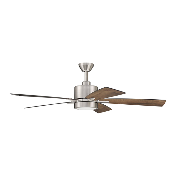
- Página 1 ITEM #4143805 CHANDLER LED CEILING FAN MODEL #CHA52BNK5LR Español p. 20 ATTACH YOUR RECEIPT HERE Purchase Date 4007498 Questions, problems, missing parts? Before returning to your retailer, call our customer service department at 1-800-527-1292, 8:30 a.m. - 5 p.m., CST, Monday - Friday.
-
Página 2: Tabla De Contenido
TABLE OF CONTENTS Safety Information ......................... 2 Package Contents ........................ 4 Hardware Contents ........................... 5 Preparation ........................... 5 Initial Installation ........................5 Downrod-Style Fan Mounting ....................7 Closemount-Style Fan Mounting ................... 9 Wiring ...........................11 Final Installation ........................12 Operating Instructions ......................15 Care and Maintenance ...................... - Página 3 SAFETY INFORMATION DANGER When using an existing outlet box, make sure the outlet box is securely attached to the building structure and can support the full weight of the fan. Failure to do this can result in serious injury or death.
-
Página 4: Package Contents
PACKAGE CONTENTS PART DESCRIPTION PART DESCRIPTION QUANTITY QUANTITY Downrod Motor Plate Screw (preassembled) Canopy Blade Arm Mounting Bracket Shade Motor Housing Pin (preassembled) Yoke Cover Clip (preassembled) LED Light Kit Remote Control Receiver Canopy Mounting Screw Remote Pack (preassembled) Fitter Plate Motor Screw/Washer (preassembled) + 1 extra... -
Página 5: Hardware Contents
HARDWARE CONTENTS (shown actual size) Fiber Blade Screw Blade Wire Washer Connector Qty. 15 Qty. 15 + 1 extra Qty. 4 + 1 extra PREPARATION Before beginning assembly of product, make sure all parts are present. Place motor on carpet or on foam to avoid damage to finish. - Página 6 INITIAL INSTALLATION 2. Determine mounting method to use. A. Downrod mount (standard or angled ceiling). B. Closemount (standard ceiling only). 19° max. IMPORTANT: If using the angle mount, check to make sure the ceiling angle is not steeper than 19°. *Helpful Hint: Downrod-style mounting is best suited for ceilings 8 ft.
-
Página 7: Important
INITIAL INSTALLATION Secure mounting bracket (C) to outlet box (not included) using screws, spring washers and flat ANGLE washers provided with the outlet box. STANDARD MOUNT MOUNT *NOTE: It is very important you use the proper hardware when installing the mounting bracket (C) as this will support the fan. - Página 8 INITIAL INSTALLATION Insert downrod (A) through canopy (B), and yoke cover (E). Thread wires from motor housing (D) up through downrod (A). Slip downrod (A) into yoke, align holes and re-install pin (N) and clip (O). Tighten set screws and then tighten nuts. Slide yoke cover (E) down until it rests on top of motor housing (D).
-
Página 9: Closemount-Style Fan Mounting
DOWNROD-STYLE FAN MOUNTING If you cut back the lead wires in Step 4, strip 1/2 in. of insulation from end of each wire -- WHITE, BLACK, GREEN and BLUE. Twist stripped ends of each strand of wire within the insulation with pliers (not included). - Página 10 CLOSEMOUNT-STYLE FAN MOUNTING Remove every other preassembled screw and lock washer from top of motor housing (D). Screw Lock Washer Pull wires up through hole in the middle of the Screw canopy (B) and attach canopy (B) to motor housing (D) using the three previously removed Lock screws and lock washers.
-
Página 11: Wiring
WIRING WARNING: To reduce the risk of fire, electrical shock or personal injury, wire connectors provided with this fan are designed to accept only one 12-gauge house wire and two lead wires from the fan. If your house wire is larger than 12-gauge or there is more than one house wire to connect to the corresponding fan lead wires, consult an electrician for the proper size wire connectors to use. -
Página 12: Final Installation
WIRING Wrap electrical tape (not included) around each individual wire connector (CC) down to the wire. WARNING: Make sure no bare wire or wire strands are visible after making connections. Place GREEN and WHITE connections on opposite side of the outlet box from the BLACK and BLUE (if applicable) connections. - Página 13 FINAL INSTALLATION DANGER: To reduce the risk of serious bodily injury, DO NOT use power tools to assemble the blades (J). If screws are overtightened, blades (J) may crack and break. Partially insert three blade screws (AA) along with three fiber blade washers (BB) into holes in blade (J) to attach blade arm (L) to blade (J).
- Página 14 FINAL INSTALLATION 5. Partially loosen two fitter plate screws (I) on the underside of the fitter plate (H) and remove the other fitter plate screw (I). Molex Connections 6. Connect WHITE wire from LED light kit (F) to WHITE wire from motor housing (D). Connect BLUE wire from LED light kit (F) to BLUE (or BLACK) wire from motor housing (D).
-
Página 15: Operating Instructions
FINAL INSTALLATION Align slots on shade (M) with protrusions on underside of fitter plate (K). Turn shade (M) clockwise until it no longer turns. NOTE: Pull down gently on the shade (M) to make sure it is secured completely. Protrusion Slot 9. - Página 16 OPERATING INSTRUCTIONS CAUTION: “DO NOT DISPOSE OF BATTERIES IN FIRE, BATTERIES MAY EXPLODE OR LEAK.” - When disposing of household alkaline batteries, it is best to check with your local and state recycling or household hazardous waste coordinators concerning the specifics of the program in your area.
-
Página 17: Care And Maintenance
OPERATING INSTRUCTIONS 4a. In warmer weather, setting the reverse switch in the LEFT position will result in downward airflow creating a wind chill effect. 4b. In cooler weather, setting the reverse switch in the RIGHT position will result in upward airflow that can help move stagnant, hot air off the ceiling area. -
Página 18: Troubleshooting
TROUBLESHOOTING WARNING: Before beginning work, shut off the power supply to avoid electrical shock. PROBLEM POSSIBLE CAUSE CORRECTIVE ACTION Fan does not move. 1. Reverse switch not engaged. 1. Push switch firmly either left or right. 2. Power is off or fuse is blown. 2. -
Página 19: Limited Lifetime Warranty
LIMITED LIFETIME WARRANTY The distributor warrants this fan to be free from defects in workmanship and materials present at time of shipment from the factory for Lifetime limited from the date of purchase. This warranty applies only to the original purchaser. The distributor agrees to correct any defect at no charge or, at our option, replace the ceiling fan with a comparable or superior model. - Página 20 ARTÍCULO # 4143805 VENTILADOR DE TECHO LED CHANDLER MODELO # CHA52BNK5LR ADJUNTE SU RECIBO AQUÍ Fecha de compra 4007498 ¿Preguntas, problemas o piezas faltantes? Antes de volver a la tienda, llame a nuestro Departamento de Servicio al Cliente al 1-800-527-1292, de lunes a viernes de 8:30 a.m. a 5 p.m.,...
- Página 21 ÍNDICE Información de seguridad ..................... Contenido del paquete ......................23 Aditamentos ..........................24 Preparación .......................... 24 Instalación inicial ........................24 Montaje del ventilador en estilo de varilla ................26 Montaje del ventilador en estilo cerrado ................28 Cableado ..........................30 Instalación final ........................32 Instrucciones de funcionamiento ..................
-
Página 22: Información De Seguridad
INFORMACIÓN DE SEGURIDAD PELIGRO Si utiliza una caja de salida existente, asegúrese de que esté bien sujeta a la estructura del edificio y que pueda sostener el peso del ventilador. El incumplimiento de dicho paso podría provocar lesiones graves o la muerte. La estabilidad de la caja de salida es fundamental para minimizar el balanceo y el ruido en el ventilador una vez que la instalación esté... -
Página 23: Contenido Del Paquete
CONTENIDO DEL PAQUETE PIEZA DESCRIPCIÓN PIEZA CANTIDAD DESCRIPCIÓN CANTIDAD Varilla Tornillo de la placa del motor (preensamblado) Base Brazo del aspa Soporte de montaje Pantalla Carcasa del motor Pasador (preensamblado) Cubierta de la horquilla Sujetador (preensamblado) Kit de iluminación LED Receptor del control remoto Tornillo de montaje de la base (preensamblado) -
Página 24: Aditamentos
ADITAMENTOS (se muestran en tamaño real) Tornillo Arandela para para aspa aspa de fibra Conector de cables Cant.: 15 Cant.: 15 + 1 adicional + 1 adicional Cant.: 4 PREPARACIÓN Antes de comenzar a ensamblar el producto, asegúrese de tener todas las piezas. Ubique el motor sobre una alfombra o espuma para evitar dañar el acabado. - Página 25 INSTALACIÓN INICIAL 2. Determine el método de instalación que utilizará. A. Montaje de varilla (techo estándar o en ángulo). 19° máx. B. Montaje cerrado (solo para techos estándar). IMPORTANTE: si realiza la instalación en ángulo, verifique que el ángulo del techo no tenga una inclinación superior a los 19°.
-
Página 26: Montaje Estándar
INSTALACIÓN INICIAL Asegure el soporte de montaje (C) a la caja de salida (no se incluye) con los tornillos, las MONTAJE MONTAJE arandelas de resorte y las arandelas planas EN ÁNGULO ESTÁNDAR que incluye la caja de salida. *NOTA: es muy importante que use los aditamentos adecuados para instalar el soporte de montaje (C), ya que este soportará... - Página 27 MONTAJE DEL VENTILADOR EN ESTILO DE VARILLA Introduzca la varilla (A) a través de la base (B) y la cubierta de la horquilla (E). Pase los conductores desde la carcasa del motor (D) a través de la varilla (A). Deslice la varilla (A) en la horquilla, alinee los orificios y vuelva a instalar el pasador (N) y el sujetador (O).
-
Página 28: Montaje Del Ventilador En Estilo Cerrado
MONTAJE DEL VENTILADOR EN ESTILO DE VARILLA Si decidió cortar los cables conductores en el paso 4, pele 12,7 mm del aislamiento del extremo de cada cable: BLANCO, NEGRO, VERDE Y AZUL. Tuerza los extremos pelados de cada filamento de cable dentro del aislamiento con pinzas (no se incluyen). - Página 29 MONTAJE DEL VENTILADOR EN ESTILO CERRADO Retire cada otro tornillo preensamblado y arandela de seguridad de la parte superior de la carcasa del motor (D). Tornillo Arandela de seguridad Pase los cables hacia arriba a través del orificio en el centro de la base (B) y fije la base (B) Tornillo a la carcasa del motor (D) con los tres tornillos Arandela de...
-
Página 30: Cableado
CABLEADO ADVERTENCIA: para reducir el riesgo de incendios, descargas eléctricas o lesiones personales, los conectores de cables incluidos con este ventilador están diseñados para soportar solo un cable de la casa de calibre 12 y dos cables conductores del ventilador. Si el cable de la casa es de un calibre superior a 12 o hay más de un cable para conectar a los cables conductores del ventilador correspondientes, consulte a un electricista cuál es el tamaño adecuado de los conectores de cables que debe utilizar. -
Página 31: Instalación Final
CABLEADO Cubra con cinta aislante (no se incluye) cada conector de cables (CC) individual hacia abajo del cable. ADVERTENCIA: asegúrese de que no haya conductores desnudos ni filamentos de cables visibles después de hacer las conexiones. Coloque los cables VERDE y BLANCO en el lado opuesto de la caja de salida con respecto a las conexiones de los cables NEGRO y AZUL. - Página 32 INSTALACIÓN FINAL PELIGRO: para reducir el riesgo de lesiones corporales graves, NO utilice herramientas eléctricas para ensamblar las aspas (J). Si los tornillos están demasiado apretados, las aspas (J) se pueden agrietar y quebrar. Inserte parcialmente tres tornillos para aspas (CC) junto con tres arandelas de fibra para aspa (BB) en los orificios del aspa (J) para fijar el brazo del aspa (L) al aspa (J).
- Página 33 INSTALACIÓN FINAL 5. Afloje parcialmente dos tornillos de la placa de soporte (I) en la parte inferior de la placa de soporte (I) y retire el otro tornillo de la placa de soporte (I). Conexiones molex 6. Conecte el conductor BLANCO del kit de iluminación LED (F) con el conductor BLANCO de la carcasa del motor (D).
-
Página 34: Instrucciones De Funcionamiento
INSTALACIÓN FINAL 8. Alinee las ranuras de la pantalla (M) con las protuberancias en la parte inferior de la placa de soporte (H). Gire la pantalla (M) en dirección de las manecillas del reloj hasta que no gire más. NOTA: jale suavemente la pantalla (M) hacia abajo para asegurarse de que esté... - Página 35 INSTRUCCIONES DE FUNCIONAMIENTO PRECAUCIÓN: "NO ARROJE LAS BATERÍAS AL FUEGO, PUEDEN EXPLOTAR O FILTRARSE”. - Antes de desechar baterías alcalinas domésticas, se recomienda consultar a los coordinadores de residuos domésticos peligrosos o de reciclaje locales y estatales para solicitarles información específica sobre el programa vigente en su zona.
-
Página 36: Cuidado Y Mantenimiento
INSTRUCCIONES DE FUNCIONAMIENTO 4a. En climas más cálidos la configuración del interruptor de reversa en la posición a la IZQUIERDA creará un flujo de aire descendente que generará un efecto de viento refrescante. 3b. En climas más fríos la configuración del interruptor de reversa en la posición a la DERECHA creará... -
Página 37: Solución De Problemas
SOLUCIÓN DE PROBLEMAS ADVERTENCIA: antes de comenzar cualquier trabajo, desconecte el suministro de electricidad para evitar descargas eléctricas. PROBLEMA CAUSA POSIBLE ACCIÓN CORRECTIVA El ventilador no 1. El interruptor de reversa no está 1. Mueva firmemente el interruptor se mueve. activado. -
Página 38: Garantía Limitada De Por Vida
GARANTÍA LIMITADA DE POR VIDA El distribuidor garantiza que este ventilador no presenta defectos en la mano de obra ni en los materiales presentes al momento del transporte desde la fábrica durante un período limitado de por vida a partir de la fecha de compra. Esta garantía es válida solo para el comprador original. El distribuidor acepta reparar cualquier defecto sin cargo o, según nuestro criterio, remplazar el ventilador de techo por un modelo comparable o superior.