Tabla de contenido
Publicidad
Idiomas disponibles
Idiomas disponibles
Enlaces rápidos
Publicidad
Tabla de contenido

Manuales relacionados para Checchi & Magli TOP 24


Resumen de contenidos para Checchi & Magli TOP 24
- Página 1 TOP 24 MANUALE D’USO E MANUTENZIONE Istruzioni originali USE AND MAINTENANCE MANUAL Original instruction MANUEL D’UTILISATION ET D’ENTRETIEN Notices originales BEDIENUNGS-UND WARTUNGSANLEITUNG Originalanleitung MANUAL DE USO Y MANTENIMIENTO Instrucciones originales Cod. 998730/02 01/2022...
- Página 3 SOMMARIO 1 INFORMAZIONI GENERALI ........................1 2 INFORMAZIONI TECNICHE ........................2 3 INFORMAZIONI SULLA SICUREZZA ......................8 4 INFORMAZIONI SULLA MOVIMENTAZIONE E IL MONTAGGIO ............9 5 INFORMAZIONI SULLE REGOLAZIONI ....................11 6 INFORMAZIONI SULL’USO ........................19 7 INFORMAZIONI SULLA MANUTENZIONE ..................26 8 INFORMAZIONI SULLE SOSTITUZIONI ....................30 INDICE ANALITICO Accessori opzionali ............................7 Attacco e distacco della macchina operatrice dalla trattrice ............
- Página 4 Pulizia della macchina operatrice ......................28 Pulizia del vomere aprisolco ........................27 Raccomandazioni di sicurezza per la manutenzione ................ 26 Raccomandazioni di sicurezza per la movimentazione e il montaggio ........9 Raccomandazioni di sicurezza per le regolazioni ................11 Raccomandazioni di sicurezza per le sostituzioni ................30 Raccomandazioni di sicurezza per l’uso....................
-
Página 5: Informazioni Generali
INFORMAZIONI GENERALI Scopo del manuale Questo manuale è stato realizzato dal costruttore per Per evidenziare alcune parti di testo, rilevanti ai fini della fornire le informazioni necessarie e i criteri da seguire a sicurezza o per indicare informazioni importanti, sono tutti coloro che interagiscono con la trapiantatrice, nel stati adottati alcuni simboli il cui significato è... -
Página 6: Glossario
INFORMAZIONI GENERALI Modalità di richiesta assistenza Le richieste di assistenza tecnica dovranno essere indiriz- Per ogni richiesta di assistenza tecnica riguardante la zate al Servizio di Assistenza Tecnica del costruttore o ai macchina operatrice indicare i dati riportati sulla tar- centri di assistenza autorizzati. -
Página 7: Elementi Principali
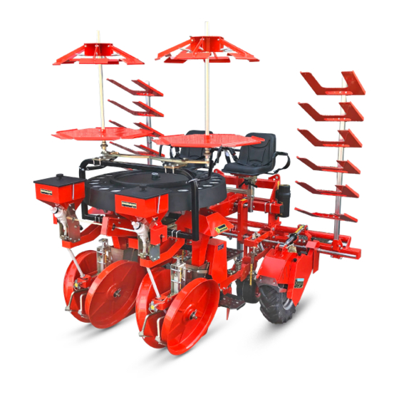
INFORMAZIONI TECNICHE Gli organi mobili sono azionati dalle ruote motrici della pressano il terreno sulla zolla della piantina. macchina operatrice (quando sono a contatto con il ter- La macchina operatrice è prodotta in più modelli che reno) e dalla marcia della trattrice. differiscono principalmente per il numero di unità... -
Página 8: Caratteristiche Tecniche
INFORMAZIONI TECNICHE Caratteristiche tecniche Dimensioni d’ingombro L’illustrazione raffigura le dimensioni d’ingombro delle macchine operatrici. TOP 24/2 TOP 24/4 TRIUM/2 TOP 24/6 TOP24/8 UN41-0875UA Le dimensioni sono espresse in centimetri. Dati tecnici TOP 24/2 TOP 24/4 TOP 24/6 TOP 24/8 Potenza trattrice richiesta... -
Página 9: Pendenze Ammissibili
40054 – BUDRIO (BOLOGNA) - ITALIA Dichiara sotto la propria responsabilità che le macchine Budrio CHECCHI & MAGLI s.r.l trapiantatrici in oggetto: TOP 24/2 - 24/4 - 24/6 - 24/8 Legale rappresentante sono conformi ai Requisiti Essenziali di Sicurezza e di Tu- Nerio Checchi tela della Salute di cui alla Direttiva 2006/42/CE. -
Página 10: Segnali Di Sicurezza E Informazione
Z = 17 DISTANZE 14-50 Z = 17 Z = 17 RAPID SHIFT indica, in funzione dell’interpianta Z = 17 402770/01 TOP 24 BUDRIO (BO) (14÷50), i pignoni da scegliere. 88 94 101 12-5/8 13-3/4 16-1/8 17-3/4 18-7/8... -
Página 11: Uso Previsto
Porta-vassoi trasversale 2 ripiani TOP 24 - 250 cm Porta-vassoi trasversale 2 ripiani TOP 24 - 300 cm Porta-vassoi trasversale 2 ripiani TOP 24 - 350 cm - extra avvitato Porta-vassoi trasversale 224 ripiani TOP 24 - 400 cm - extra avvitato... -
Página 12: Informazioni Sulla Sicurezza
Vomere stretto TOP-TRIUM-BEST L=8 Vomere stretto TOP-TRIUM-BEST L=14 Vomere stretto TOP-TRIUM-BEST L=24 Vomere medio TOP-TRIUM-BEST L=33 Vomere largo TOP-TRIUM-BEST L=43 Sedile supplementare TOP 24 Skid TOP-TRIUM-BEST Disco taglio TOP-TRIUM-BEST attacco ruota Separatore di zolle TOP-TRIUM-BEST Prolunga distributore per piante alte e frondose... -
Página 13: Movimentazione E Sollevamento Dell'iMballo
INFORMAZIONI SULLA MOVIMENTAZIONE E IL MONTAGGIO Raccomandazioni di sicurezza per la movimentazione e il montaggio Eseguire la movimentazione e il trasporto secondo le Il personale addetto alla movimentazione del carico informazioni fornite dal costruttore riportate diret- deve possedere capacità, esperienza e deve avere la tamente sulla macchina, sull’imballo e nelle istruzio- padronanza del mezzo di sollevamento utilizzato. -
Página 14: Disimballo E Montaggio
Nella fase di sollevamento prestare attenzione alle Nei modelli TOP 24/2, TOP 24/6 deve essere smontato il oscillazioni del carico perché il punto di presa non è sedile per permettere il montaggio dell’attrezzo di solle- mai perfettamente baricentrico. -
Página 15: Informazioni Sulle Regolazioni
INFORMAZIONI SULLA MOVIMENTAZIONE E IL MONTAGGIO UN41-0886UA Procedere come descritto. figura. 1) Utilizzare per il sollevamento l’apposito attrezzo (A) 3) Verificare che il perno (B) sia bloccato dalla spina di fornito a corredo della macchina operatrice. sicurezza (C) e che le catene (D) siano stabilmente agganciate al telaio. -
Página 16: Regolazione Simmetrica Delle Ruote Costipatrici Con Il Vomere
INFORMAZIONI SULLE REGOLAZIONI Procedere come descritto. 1) Agire sul fermo (A) per liberare il po- mello (B). 2) Agire sul pomello (B) per allontanare o avvicinare le ruote costipatrici (C) dal vomere (D). 3) Dopo aver effettuato la regolazione bloccare il pomello (B) con il fermo (A). -
Página 17: Regolazione Raschietto Ruote Costipatrici
INFORMAZIONI SULLE REGOLAZIONI Regolazione raschietto ruote costipatrici Il raschietto serve a pulire le ruote costipa- trici dall’accumulo di terreno e dai detriti. Procedere come descritto. 1) Allentare la vite (A). 2) Ruotare il raschietto (B) fino a portarlo nella posizione desiderata. 3) Avvitare la vite (A). -
Página 18: Regolazione Carico Del Ruotino
INFORMAZIONI SULLE REGOLAZIONI Regolazione carico del ruotino Procedere come descritto. 1) Ruotare il pomello (A) in senso orario per aumentare il carico del ruotino (B) sul terreno. 2) Ruotare il pomello in senso antiorario per diminuire il carico del ruotino sul terreno. - Página 19 INFORMAZIONI SULLE REGOLAZIONI Procedere come descritto. Posizionare il vomere (F) come richiesto dal lavoro da eseguire. Allentare il dado ad alette (A). Verificare che il dispositivo Plant Control sia all’in- Ruotare la leva di sicurezza (B). terno del vomere. Spingere in avanti il vomere e ruotarlo verso il bas- Verificare che la leva di sicurezza (B) blocchi il vome- Allentare il dado (C).
-
Página 20: Regolazione Della Fase Distributore-Espulsore
INFORMAZIONI SULLE REGOLAZIONI Regolazione della fase distributore-espulsore Quando la pianta cade nel vomere (C), l’espulsore (B) Se le condizioni consentono di trapiantare ad alta velo- deve essere in posizione arretrata per poi iniziare la spin- cità o a bassa velocità, è possibile mantenere la corretta ta di espulsione. - Página 21 INFORMAZIONI SULLE REGOLAZIONI Regolazione del disinnesto automatico di sicurezza Il disinnesto automatico ha lo scopo di preservare gli organi di trasmissione da sovraccarichi (ad esempio in caso di bloc- caggio del distributore ecc.). Il dispositivo, installato su ogni unità di trapianto, è...
- Página 22 INFORMAZIONI SULLE REGOLAZIONI Regolazione tensione catena di rinvio INFORMAZIONE Non tensionare eccessivamente la ca- tena per prevenire un’usura precoce della catena e dei pignoni. Procedere come descritto. 1) Svitare i dadi (A). 2) Rimuovere il carter (B). 3) Allentare il dado (C). 4) Muovere il tenditore per tensionare correttamente la catena.
-
Página 23: Informazioni Sull'USo
INFORMAZIONI SULLE REGOLAZIONI UN41-0904UA INFORMAZIONI SULL’USO Raccomandazioni di sicurezza per l’uso Consentire l’uso della macchina solo a personale au- d’uso della trattrice). torizzato, in buona salute, adeguatamente formato e Pulire gli elementi di appoggio dei piedi per evitare dotato di idonea patente di guida per la trattrice. perdite di equilibrio nelle fasi di salita e discesa dalla Accertare che non vi siano persone, bambini o anima- macchina operatrice. -
Página 24: Attacco E Distacco Della Macchina Operatrice Dalla Trattrice
INFORMAZIONI SULL’USO UN41-0905UA Attacco e distacco della macchina operatrice dalla trattrice Posizionare la macchina operatrice su terreno soli- ATTENZIONE do, in piano e privo di rischi. Il collegamento della macchina operatrice alla trattri- Avvicinare la trattrice alla struttura di sollevamento ce è... -
Página 25: Sistemazione Sedile
INFORMAZIONI SULL’USO UN41-0906UA - Per il distacco procedere come descritto. il perno (M) e la spina di sicurezza (L). 1) Scegliere una zona pianeggiante e solida per par- 4) Arrestare il motore della trattrice e sfilare la chiave di cheggiare la macchina operatrice - trattrice. accensione dal cruscotto. - Página 26 INFORMAZIONI SULL’USO Sistemazione pedana Procedere come descritto. 1) Allentare i dadi (A). 2) Muovere la pedana (B) nella posizio- ne di massima comodità. 3) Avvitare i dadi (A). UN41-0908UA Cambio interpianta Le tabelle indicano le possibili distanze tra una piantina La distanza tra una piantina e quella successiva (inter- e quella successiva che si possono ottenere con il cam- pianta) dipende dai pignoni in presa del cambio rapid...
-
Página 27: Cambio Rapporto Trasmissione (Rapid Shift)
INFORMAZIONI SULL’USO Cambio rapporto trasmissione (Rapid Shift) INFORMAZIONE ATTENZIONE Il cambio del rapporto della trasmissione ha lo scopo Spegnere il motore della trattrice, disinserire e custo- di ottenere l’interpianta richiesta. dire la chiave di accensione per prevenire il pericolo Fare riferimento al capitolo “Cambio interpianta” per di infortunio durante la fase del cambio del rapporto scegliere la coppia di pignoni da usare compresa nel- di trasmissione. -
Página 28: Operazioni Preliminari
INFORMAZIONI SULL’USO UN41-0911UA Operazioni preliminari Operazioni in fase di trapianto 1) Per evitare sovraccarichi l’operatore a bordo della Prima di iniziare la fase di trapianto posizionare la mac- china in piano ed effettuare le operazioni elencate. trattrice deve abbassare la macchina operatrice con la trattrice in lento avanzamento. -
Página 29: Lavoro Notturno O Con Scarsa Visibilità
INFORMAZIONI SULL’USO Lavoro notturno o con scarsa visibilità Il lavoro notturno o la scarsa visibilità aumentano i rischi Durante i lavori notturni o in condizione di scarsa visibi- derivanti dall’uso della macchina. lità predisporre un’adeguata illuminazione per operare in sicurezza. Trasporto della macchina operatrice con funi e bloccare le ruote con cunei. -
Página 30: Circolazione Su Strade Pubbliche
INFORMAZIONI SULL’USO Circolazione su strade pubbliche Nel trasferimento del complesso macchina operatrice- ATTENZIONE trattrice osservare le prescrizioni del codice della strada. E’ vietato trasportare persone e/o cose sulla macchi- E’ obbligatorio bloccare l’attacco a tre punti con gli ap- na operatrice. positi puntoni (A) per impedire qualsiasi oscillazione del- Prima di mettersi su strade togliere tutti i vassoi dal la macchina operatrice e adeguare la velocità... -
Página 31: Intervalli Di Manutenzione
INFORMAZIONI SULLA MANUTENZIONE Tabella intervalli di manutenzione Per garantire un costante ed efficiente funzionamento operazioni di manutenzione programmata previste dal della macchina in condizioni di sicurezza effettuare le costruttore. Intervalli di manutenzione Intervallo Componente Tipo di intervento Riferimento manuale Distributore Pulizia Ogni ora di lavoro... -
Página 32: Controllo Pneumatici
INFORMAZIONI SULLA MANUTENZIONE Controllo struttura attacco terzo punto Pulire la macchina operatrice (vedere “Pulizia della mac- mazioni, fessurazioni, ecc. china operatrice”). Se si notano indebolimenti e/o piccole fessurazioni è Eseguire un controllo visivo della struttura attacco terzo necessario rivolgersi immediatamente presso l’officina punto al fine di individuare cedimenti strutturali, defor- autorizzata o direttamente al costruttore. -
Página 33: Schema Punti Di Lubrificazione
INFORMAZIONI SULLA MANUTENZIONE Schema punti di lubrificazione Lubrificare gli organi raffigurati nei tempi e nei modi in- di inquinare il lubrificante distribuito. dicati. Usare grasso universale per autotrazione di macchinari Prima di effettuare la lubrificazione pulire accuratamen- agricoli e industriali, idrorepellente con punto di goccia te i componenti interessati e gli ingrassatori per evitare 180°. - Página 34 INFORMAZIONI SULLA MANUTENZIONE Tabella coppie di serraggio bulloneria Coppie serraggio bulloneria Diametro Passo Classe di resistenza Classe di resistenza Classe di resistenza filettatura filettatura (mm) 8.8 (Nm) 10.9 (Nm) 12.9 (Nm) 13.0 16.0 1,25 23.0 32.0 39.0 M 10 46.0 64.0 77.0 M 12...
- Página 35 INFORMAZIONI SULLE SOSTITUZIONI Procedere come descritto. Svitare la vite (F) e rimuovere il pignone (G). Azionare la leva (C) per sollevare la ruota con lo sco- Montare il nuovo pignone e avvitare la vite (F). po di ridurre la tensione della catena. INFORMAZIONE Svitare i dadi (A).
- Página 36 INFORMAZIONI SULLE SOSTITUZIONI Sostituzione catena disinnesto UN41-0918UA 9) Unire la catena con la maglia di giunzione. Procedere come descritto. Svitare le viti (A). INFORMAZIONE Rimuovere il carter (B). Non tensionare eccessivamente la catena per preve- Svitare le viti (C). nire un’usura precoce della catena e dei pignoni. Rimuovere il carter (D).
- Página 37 INFORMAZIONI SULLE SOSTITUZIONI INFORMAZIONE Montare la catena con la maglia di giunzione orientata nel verso indicato in figura. Unire la catena con la maglia di giun- zione. INFORMAZIONE Non tensionare eccessivamente la ca- tena per prevenire un’usura precoce della catena e dei pignoni. Muovere il tenditore per tensionare correttamente la catena.
-
Página 38: Sostituzione Vomere
INFORMAZIONI SULLE SOSTITUZIONI Sostituzione catena rinvio Rapid Shift Procedere come descritto. Svitare i dadi (A). Rimuovere le rondelle (B). Rimuovere il carter (C). Staccare la molla (D) dal tenditore (E). Smontare la maglia di giunzione (F). Rimuovere la catena dai pignoni. Posizionare la nuova catena sul ten- ditore e sui pignoni. -
Página 39: Sostituzione Piatto Flessibile
INFORMAZIONI SULLE SOSTITUZIONI 14) Posizionare la rondella (E). - Eseguire le stesse operazioni per effettuare la sostitu- zione nelle altre unità di trapianto installate. 15) Avvitare il dado ad alette (B). 16) Montare l’anello elastico. Sostituzione piatto flessibile Procedere come descritto. Allentare leggermente il dado ad alette (A). - Página 40 INFORMAZIONI SULLE SOSTITUZIONI Lingua italiana Uso e manutenzione...
- Página 41 SUMMARY 1 GENERAL INFORMATION ..........................1 2 TECHNICAL INFORMATION ........................2 3 SAFETY INFORMATION ..........................8 4 HANDLING AND ASSEMBLY INFORMATION ..................9 5 ADJUSTMENT INFORMATION ......................11 6 INFORMATION FOR USE ........................19 7 MAINTENANCE INFORMATION ......................26 8 INFORMATION CONCERNING REPLACEMENTS ................30 ANALYTICAL INDEX Adjusting the automatic safety release function ................
- Página 42 Improper and unauthorised uses ........................7 Information and safety signs .........................6 Lifting the work vehicle..........................10 Lubrication points diagram ........................29 Main parts ................................3 Maintenance interval schedule ......................... 27 Manufacturer’s registration details and work vehicle identification details ........1 Night-time work or poor visibility conditions ..................25 Nut and bolt tightness check ........................
-
Página 43: General Information
GENERAL INFORMATION Aim of the manual This instruction manual is produced by the manufacturer To highlight certain parts of the manual’s contents to provide all those who have dealings with the planting deemed important for safety or information reasons the machine (which may also be referred to hereinafter as following symbols have been used, whose meanings are the ‘work vehicle’) with all the necessary information and... -
Página 44: Disclaimer Notice
GENERAL INFORMATION Assistance request procedure All requests for technical assistance must be made to the Whenever making requests for technical assistance con- manufacturer’s Technical Assistance Service or the au- cerning the work vehicle, remember to quote the data thorised service centres. shown on the data plate and the fault encountered. -
Página 45: Main Parts
TECHNICAL INFORMATION The moving parts are driven by the works vehicle’s driv- up and compact the soil around the seedling root ball. ing wheels (when these are touching the ground) and The work vehicle is manufactured in several models the movement of the tractor. which differ mainly in terms of the number of planting The seedling falls from the dispenser into the furrow cre- units featured. -
Página 46: Technical Characteristics
TECHNICAL INFORMATION Technical characteristics Overall dimensions The illustration shows the work vehicles’ overall dimensions. TOP 24/2 TOP 24/4 TRIUM/2 TOP 24/6 TOP24/8 UN41-0875UA Dimensions are stated in centimetres. Specifications TOP 24/2 TOP 24/4 TOP 24/6 TOP 24/8 Required tractor power... -
Página 47: Permitted Gradients
40054 – BUDRIO (BOLOGNA) - ITALY Hereby declares, under its own responsibility that the Budrio CHECCHI & MAGLI s.r.l planting machine in question, i.e. models TOP 24/2 - 24/4 Legal representative - 24/6 - 24/8, comply with the Essential and Health Safety Nerio Checchi Requirements provided for by Directive 2006/42/CE. -
Página 48: Information And Safety Signs
Z = 17 Z = 17 RAPID SHIFT Rapid Shift gearbox on the drive wheel, Z = 17 402770/01 TOP 24 BUDRIO (BO) this shows which pinions to select de- pending on the plant spacing (14÷50). 88 94 101 12-5/8... -
Página 49: Permitted Use
Transversal tray holder 2 shelves TOP 24- 250 cm Transversal tray holder 2 shelves TOP 24- 300 cm Transversal tray holder 2 shelves TOP 24- 350 cm – secured very tightly Transversal tray holder 224 shelves TOP 24- 400 cm – secured very tightly Transversal tray holder 2 shelves TOP 24- 450 cm –... -
Página 50: General Safety Information
Narrow ploughshare TOP-TRIUM-BEST L=8 Narrow ploughshare TOP-TRIUM-BEST L=14 Narrow ploughshare TOP-TRIUM-BEST L=24 Medium ploughshare TOP-TRIUM-BEST L=33 Wide ploughshare TOP-TRIUM-BEST L=43 Extra seat TOP 24 Skid TOP-TRIUM-BEST Cutting disc TOP-TRIUM-BEST wheel attachment Root ball separator TOP-TRIUM-BEST Dispenser extension for tall, leafy plants... -
Página 51: Handling And Lifting The Packed Unit
HANDLING AND ASSEMBLY INFORMATION Safety advice for handling and assembly Perform handling and transportation manoeuvres The staff assigned to handling the load must have the in compliance with the information provided by the required ability and experience and must be skilled manufacturer and stated directly on the machine, on in the use of the lifting means adopted. -
Página 52: Unpacking And Assembly
During lifting watch out for the load swinging, as For models TOP 24/2, TOP 24/6, the seat must be re- the hook-up point is never perfectly at the centre of moved to allow the lifting means to be fitted. -
Página 53: Safety Advice For The Adjustments
HANDLING AND ASSEMBLY INFORMATION UN41-0886UA 3) Check that the pin (B) is locked with the safety pin Proceed as outlined below. (C) and that the chains (D) are secured firmly to the 1) Use the specific tool (A) provided with the work vehi- frame. -
Página 54: Adjusting The Symmetry Between The Packing Wheels And The Ploughshare
ADJUSTMENT INFORMATION Proceed as outlined below. 1) Use the lock (A) to release the knob (B). 2) Turn the knob (B) to move the pack- ing wheels (C) closer to or away from the ploughshare (D). 3) After adjustment secure the knob (B) with the lock (A). -
Página 55: Adjusting The Packing Wheel Scraper
ADJUSTMENT INFORMATION Adjusting the packing wheel scraper The scraper is used to clean the packing wheels, removing any soil and debris that has built up. Proceed as outlined below. 1) Loosen the screw (A). 2) Turn the scraper (B) until it reaches the desired position. -
Página 56: Adjusting The Small Wheel Load
ADJUSTMENT INFORMATION Adjusting the small wheel load Proceed as outlined below. 1) Turn the knob (A) clockwise to in- crease the small wheel (B) load on the ground. 2) Turn the knob anticlockwise to de- crease the load of the small wheel on the ground. - Página 57 ADJUSTMENT INFORMATION Proceed as outlined below. Position the ploughshare (B) as required for the work to be performed. Loosen the wing nut (A). Check that the Plant Control device is inside the Turn the lock lever (B). share. Push the share forwards and turn it so it is facing Make sure that the share is secured in place with the downwards.
-
Página 58: Adjusting The Dispensing/Ejection Timing
ADJUSTMENT INFORMATION Adjusting the dispensing/ejection timing When the plant falls into the ploughshare (C), the ejector If the conditions allow high- or low-speed planting, cor- (B) should be in the rear position and should then start rect timing between the dispenser and the ejector can pushing the plant to eject it. - Página 59 ADJUSTMENT INFORMATION Adjusting the automatic safety release function The automatic release is designed to pro- tect the transmission components from overloads (e.g. if the dispenser jams, etc.). The device, installed on every planting unit, is already set by the manufacturer during the testing stage, but can be ad- justed by the user according to require- ments.
- Página 60 ADJUSTMENT INFORMATION Adjusting the transmission chain tension NOTICE Do not overtighten the chain as this could cause premature wear of the chain and the sprockets. Proceed as outlined below. 1) Unscrew the nuts (A). 2) Remove the casing (B). 3) Loosen the nut (C). 4) Move the tensioner to tension the chain correctly.
-
Página 61: Safety Advice Concerning Use
ADJUSTMENT INFORMATION UN41-0904UA INFORMATION FOR USE Safety advice concerning use This ensures the machine can only be used by fit and for the tractor with the equipment mounted on it healthy personnel, who are suitably trained and au- (see tractor user manual). thorised, and hold the appropriate category driving Keep the parts where operators tread clean to pre- licence for a tractor. -
Página 62: Hitching And Unhitching The Work Vehicle To And From The Tractor
INFORMATION FOR USE UN41-0905UA Hitching and unhitching the work vehicle to and from the tractor Position the work vehicle on flat, solid ground in a WARNING risk-free area. Hitching the work vehicle up to the tractor is one of Move the tractor so that it is positioned near the the riskiest moments as it could required the involve- work vehicle lift frame. -
Página 63: Seat Positioning
INFORMATION FOR USE UN41-0906UA - For unhitching, proceed as outlined below. (L). 1) Select an area with flat, solid ground to park the work 4) Switch off the tractor engine and remove the ignition vehicle - tractor. key from the dashboard. 2) Using the tractor’s controls, lower the work vehicle to 5) Take out the lock pin (H) and remove the pin (G). - Página 64 INFORMATION FOR USE Positioning the footboard Proceed as outlined below. 1) Loosen the nuts (A). 2) Move the footboard (B) into the most comfortable position. 3) Tighten the nuts (A). UN41-0908UA Plant changeover The tables show the possible distances between one The distance between one seedling and the next (plant seedling and the next that can be obtained with the spacing) depends on the pinions engaged in the Rapid...
-
Página 65: Changing The Transmission Ratio (Rapid Shift)
INFORMATION FOR USE Changing the transmission ratio (Rapid Shift) NOTICE WARNING The aim of the change of the transmission ratio is to Switch off the tractor engine, remove the ignition obtain the required plant spacing. key, and store in a safe place to prevent an accident See the “Plant changeover”... -
Página 66: Preliminary Operations
INFORMATION FOR USE UN41-0911UA Preliminary operations Planting operations 1) To prevent overloads the operator on the tractor Before starting planting, position the machine on flat ground and carry out the following operations. must lower the work vehicle with the tractor moving forwards at low speed. -
Página 67: Night-Time Work Or Poor Visibility Conditions
INFORMATION FOR USE Night-time work or poor visibility conditions Working at night or in low visibility conditions increases During work at night or in poor visibility conditions, the risks that derive from the use of the machine. proper lighting must be provided to ensure safe work. Transporting the work vehicle Units which are narrower than the maximum width al- WARNING... -
Página 68: Transit On Public Roads
INFORMATION FOR USE Transit on public roads When transporting the work vehicle/tractor assembly, WARNING the regulations of the highway code must always be complied with. It is prohibited to carry people and/or things on the work vehicle. Obligatorily, the three-point hitch must be secured with Before any on-the-road driving remove all the trays the relative bars (A) to prevent the work vehicle swing- from the tray holder and clean the working parts and... -
Página 69: Maintenance Interval Schedule
MAINTENANCE INFORMATION Maintenance interval schedule To guarantee constant, efficient and safe machine oper- by the manufacturer is carried out. ation, ensure all the scheduled maintenance envisaged Maintenance intervals Interval Component Type of work Manual reference Dispenser Cleaning Every work hour Ploughshare Cleaning See “Cleaning the ploughshare”... -
Página 70: Tyre Check
MAINTENANCE INFORMATION Checking the structure of the three-point hitch Clean the work vehicle (see “Cleaning the work vehi- If you notice weakening and/or small cracks, contact the cle”). authorised service centre immediately or the manufac- turer directly. Visually inspect the three-point hitch structure to check for structural failures, warping, cracks, etc.. -
Página 71: Lubrication Points Diagram
MAINTENANCE INFORMATION Lubrication points diagram Lubricate the parts shown at the times and in the ways the lubricant.di inquinare il lubrificante distribuito. specified. Use universal grease for traction in farming and industri- Before lubricating, clean the components concerned al machinery, which is water-repellent with a 180° drop and the greasing nipples to prevent contamination of point. - Página 72 MAINTENANCE INFORMATION Nuts and bolts tightening torques chart Nuts and bolts tightening torques Resistance class Resistance class Resistance class Thread diameter Thread pitch (mm) 8.8 (Nm) 10.9 (Nm) 12.9 (Nm) 13.0 16.0 1,25 23.0 32.0 39.0 M 10 46.0 64.0 77.0 M 12 1,75...
-
Página 73: Replacing The Driving Wheel Chain (Rapid Shift)
INFORMATION CONCERNING REPLACEMENTS Proceed as outlined below. Unscrew the screw (F) and remove the pinion (G). Move the lever (C) to lift the wheel in order to slack- Fit the new pinion and tighten the screw (F). en off the chain. NOTICE Unscrew the nuts (A). - Página 74 INFORMATION CONCERNING REPLACEMENTS Replacing the release chain UN41-0918UA 9) Join the chain with the connecting link. Proceed as outlined below. Undo the screws (A). NOTICE Remove the casing (B). Do not overtighten the chain as this could cause pre- Undo the screws (C). mature wear of the chain and the sprockets.
- Página 75 INFORMATION CONCERNING REPLACEMENTS NOTICE Fit the chain with the joining link posi- tioned as shown in the figure. Join the chain with the connecting link. NOTICE Do not overtighten the chain as this could cause premature wear of the chain and the sprockets. Move the tensioner to tension the chain correctly.
-
Página 76: Replacing The Ploughshare
INFORMATION CONCERNING REPLACEMENTS Replacing the Rapid Shift transmission chain Proceed as outlined below. Unscrew the nuts (A). Remove the washers (B). Remove the casing (C). Remove the spring (D) from the ten- sioner (E). Remove the joining link (F). Remove the chain from the pinions. Place the new chain on the tensioner and pinions. -
Página 77: Replacing The Flexible Plate
INFORMATION CONCERNING REPLACEMENTS 14) Position the washer (E). - Carry out the same procedure to make the replace- ment in the other planting units installed 15) Tighten the wing bolt (B). 16) Fit the circlip. Replacing the flexible plate Proceed as outlined below.. Slightly loosen wing nut (A). - Página 78 INFORMATION CONCERNING REPLACEMENTS English language Use and maintenance...
- Página 79 SOMMAIRE 1 INFORMATIONS GENERALES........................1 2 INFORMATIONS TECHNIQUES ........................2 3 INFORMATIONS CONCERNANT LA SECURITE ...................8 4 INFORMATIONS CONCERNANT LA MANUTENTION ET LE MONTAGE ........9 5 INFORMATIONS CONCERNANT LES REGLAGES ................11 6 INFORMATIONS CONCERNANT L’UTILISATION................19 7 INFORMATIONS CONCERNANT L’ENTRETIEN ................. 26 8 INFORMATIONS CONCERNANT LES REMPLACEMENTS .............
- Página 80 Période d’inactivité prolongée de la machine opératrice ............... 26 Principaux éléments ............................3 Problèmes, causes, solutions........................28 Protections ................................5 Recommandations concernant la sécurité durant l’utilisation ............19 Recommandations de sécurité concernant les remplacements ........... 30 Recommandations de sécurité pour l’entretien .................. 26 Recommandations de sécurité...
-
Página 81: Informations Generales
INFORMATIONS GENERALES Objectif du manuel Ce manuel a été réalisé par le fabricant pour fournir les Pour mettre en évidence certaines parties du texte, im- informations nécessaires et les critères à suivre à tous portantes pour la sécurité ou pour indiquer des infor- ceux qui interagissent avec la repiqueuse, également dé- mations importantes, on a adopté... -
Página 82: Exclusion De Responsabilité
INFORMATIONS GENERALES Modalité à suivre pour les demandes d’assistance Les demandes d’assistance technique devront être adres- Pour toute demande d’assistance technique concernant sées au Service d’Assistance Technique du constructeur la machine opératrice, indiquer les données figurant sur ou aux centres d’assistance autorisés. la plaque d’identification et le défaut relevé. -
Página 83: Principaux Éléments
INFORMATIONS TECHNIQUES Les organes mobiles sont actionnés par les roues motri- sent le terrain sur la motte du plant. ces de la machine opératrice (lorsqu’elles sont au contact La machine opératrice est produite en plusieurs modèles du sol) et par la marche du tracteur. qui diffèrent principalement par le nombre d’unités de Le plant tombe par gravité... -
Página 84: Caractéristiques Techniques
INFORMATIONS TECHNIQUES Caractéristiques techniques Dimensions d’encombrement L’illustration représente les dimensions d’encombrement des machines opératrices. TOP 24/2 TOP 24/4 TRIUM/2 TOP 24/6 TOP24/8 UN41-0875UA Les dimensions sont exprimées en centimètres. Données techniques TOP 24/2 TOP 24/4 TOP 24/6 TOP 24/8 Puissance requise pour le tracteur Distance minimale entre les rangées... -
Página 85: Pentes Admises
40054 – BUDRIO (BOLOGNA) - ITALIA Déclare, sous sa propre responsabilité, que les machines re- Budrio CHECCHI & MAGLI s.r.l piqueuses en question: TOP 24/2 - 24/4 - 24/6 - 24/8 sont Représentant légal conformes aux Exigences Essentielles de Sécurité et de Tu- Nerio Checchi telle de la Santé... -
Página 86: Signaux De Sécurité Et D'iNformation
Z = 17 RAPID SHIFT appliquée sur la boîte de vitesse rapid Z = 17 402770/01 TOP 24 BUDRIO (BO) shift et sur la roue motrice, elle indique les pignons à choisir en fonction de la distance entre les plants (14÷50). -
Página 87: Usage Prévu
Porte-cageots transversal 2 niveaux TOP 24 - 250 cm Porte-cageots transversal 2 niveaux TOP 24 - 300 cm Porte-cageots transversal 2 niveaux TOP 24 - 350 cm - supplémentaire vissé Porte-cageots transversal 224 niveaux TOP 24 - 400 cm - supplémentaire vissé... -
Página 88: Informations Générales Sur La Sécurité
Soc étroit TOP-TRIUM-BEST L=14 Soc étroit TOP-TRIUM-BEST L=24 Soc moyen TOP-TRIUM-BEST L=33 Soc large TOP-TRIUM-BEST L=43 Siège supplémentaire TOP 24 Skid TOP-TRIUM-BEST Disque de coupe TOP-TRIUM-BEST fixation roue Séparateur de mottes TOP-TRIUM-BEST Rallonge distributeur pour les plants hauts et feuillus Sincromicro Dispositif de pose tuyau d’irrigation (pose en surface) -
Página 89: Manutention Et Levage De L'eMballage
INFORMATIONS CONCERNANT LA MANUTENTION ET LE MONTAGE Recommandations relatives à la sécurité pour la manutention et le montage Exécuter la manutention et le transport en suivant Le personnel préposé à la manutention de la charge les informations fournies par le constructeur, appli- doit posséder capacité... -
Página 90: Déballage Et Montage
Durant la phase de levage, faire attention aux oscilla- Sur les modèles TOP 24/2, TOP 24/6, démonter le siège tions de la charge car le point de prise n’est jamais pour permettre le montage de l’outil de levage. - Página 91 INFORMATIONS CONCERNANT LA MANUTENTION ET LE MONTAGE UN41-0886UA 3) Vérifier que l’axe (B) est bloqué par la goupille de sé- Suivre les instructions fournies. curité (C) et que les chaînes (D) sont accrochées de 1) Pour le levage, utiliser l’outil (A) spécifique fourni façon stable au châssis.
- Página 92 INFORMATIONS CONCERNANT LES REGLAGES Suivre les instructions fournies. 1) Agir sur l’arrêt (A) pour libérer la poi- gnée (B). 2) Agir sur la poignée (B) pour éloigner ou rapprocher les roues tasseuses (C) du soc (D). 3) Après le réglage bloquer la poignée (B) avec l’arrêt (A).
- Página 93 INFORMATIONS CONCERNANT LES REGLAGES Réglage du racloir des roues tasseuses Le racloir sert à nettoyer les roues tasseu- ses en éliminant la terre et les détritus qui s’y accumulent. Suivre les instructions fournies. 1) Desserrer la vis (A). 2) Tourner le racloir (B) dans la position souhaitée.
- Página 94 INFORMATIONS CONCERNANT LES REGLAGES Réglage de la charge du rouet Suivre les instructions fournies. 1) Tourner la poignée (A) en sens horaire pour augmenter la charge du rouet (B) sur le terrain. 2) Tourner la poignée en sens inverse horaire pour réduire la charge du rouet sur le terrain.
- Página 95 INFORMATIONS CONCERNANT LES REGLAGES Suivre les instructions fournies. Positionner le soc (F) en fonction du travail à effec- tuer. Desserrer l’écrou papillon (A). Vérifier que le dispositif Plant Control se trouve à Tourner le levier de sécurité (B). l’intérieur du soc. Pousser le soc vers l’avant et le tourner vers le bas.
- Página 96 INFORMATIONS CONCERNANT LES REGLAGES Réglage de la phase distributeur-éjecteur Quand le plant tombe dans le soc (C), l’éjecteur (B) doit Si les conditions permettent de repiquer à grande vitesse se trouver en arrière pour commencer la poussée d’éjec- ou à vitesse réduite, on peut maintenir la phase correcte tion.
- Página 97 INFORMATIONS CONCERNANT LES REGLAGES Réglage du débrayage automatique de sécurité Le débrayage automatique a pour but de préserver les organes de transmission contre les surcharges (par exemple en cas de blocage du distributeur, etc.). Le dispositif, installé sur chaque unité de repiquage, a été...
-
Página 98: Réglage Du Frein
INFORMATIONS CONCERNANT LES REGLAGES Réglage de la tension de la chaîne de renvoi INFORMATION Ne pas tendre excessivement la chaîne pour prévenir une usure précoce de cette dernière et des pignons. Suivre les instructions fournies. 1) Dévisser les écrous (A). 2) Enlever le carter (B). -
Página 99: Informations Concernant L'UTilisation
INFORMATIONS CONCERNANT LES REGLAGES UN41-0904UA INFORMATIONS CONCERNANT L’UTILISATION Recommandations concernant la sécurité durant l’utilisation Ne confier l’utilisation de la machine qu’à du person- manuel d’utilisation du tracteur). nel autorisé, en bonne santé, dûment formé et muni Nettoyer les éléments d’appui des pieds pour éviter du permis de conduire pour les tracteurs. - Página 100 INFORMATIONS CONCERNANT L’UTILISATION UN41-0905UA Attelage et dételage de la machine opératrice du tracteur Positionner la machine opératrice sur un terrain so- ATTENTION lide, plat et sans risques. Le raccordement de la machine opératrice au tracteur Approcher le tracteur de la structure de soulève- est l’un des moments les plus dangereux car il pour- ment de la machine opératrice.
-
Página 101: Réglage Du Siège
INFORMATIONS CONCERNANT L’UTILISATION UN41-0906UA - Pour le dételage, suivre la description. (M) et la goupille de sécurité (L). 1) Choisir une zone plate et solide pour garer la machi- 4) Couper le moteur du tracteur et retirer la clé de ne opératrice - tracteur. -
Página 102: Agencement De La Plate-Forme
INFORMATIONS CONCERNANT L’UTILISATION Agencement de la plate-forme Suivre les instructions fournies. 1) Desserrer les écrous (A). 2) Déplacer la plate-forme (B) dans la position la plus confortable. 3) Serrer les écrous (A). UN41-0908UA Variation de l’écartement Les tableaux indiquent les distances possibles entre La distance entre deux plants dépend des pignons en deux plants que l’on peut obtenir avec la boîte de vitesse prise de la boîte de vitesses rapid shift. -
Página 103: Changement De Rapport De Transmission (Rapid Shift)
INFORMATIONS CONCERNANT L’UTILISATION Changement de rapport de transmission (Rapid Shift) INFORMATION ATTENTION Le changement de rapport de transmission a pour Couper le moteur du tracteur, extraire et conserver la but la réalisation du repiquage souhaité. clé de contact pour prévenir tout danger d’accident Voir le chapitre “Variation de l’écartement”... -
Página 104: Opérations Préliminaires
INFORMATIONS CONCERNANT L’UTILISATION UN41-0911UA Opérations préliminaires Opérations à effectuer en phase de repiquage Avant de commencer la phase de repiquage, positionner 1) Pour éviter les surcharges l’opérateur à bord du trac- la machine horizontalement et effectuer les opérations teur doit abaisser la machine opératrice avec le trac- indiquées. -
Página 105: Transport De La Machine Opératrice
INFORMATIONS CONCERNANT L’UTILISATION Travail nocturne ou en présence d’une faible visibilité Le travail nocturne ou la faible visibilité augmente les ris- Lorsqu’on travaille de nuit ou par mauvaise visibilité, ques liés à l’utilisation de la machine. disposer un éclairage adéquat pour travailler en toute sécurité. -
Página 106: Circulation Sur La Voie Publique
INFORMATIONS CONCERNANT L’UTILISATION Circulation sur la voie publique Durant le transfert du groupe machine opératrice-trac- ATTENTION teur, observer les prescriptions du code de la route. Il est interdit de transporter des personnes et/ou des Il est obligatoire de boquer l’attelage à trois points avec choses sur la machine opératrice. -
Página 107: Contrôle Du Serrage Des Boulons
INFORMATIONS CONCERNANT L’ENTRETIEN Tableau des intervalles d’entretien Pour garantir un fonctionnement constant et correct de les opérations d’entretien programmé prévues par le la machine dans des conditions de sécurité, effectuer constructeur. Intervalles d’entretien Intervalle Composant Type d’intervention Référence au manuel Distributeur Nettoyage Chaque... -
Página 108: Contrôle Des Pneus
INFORMATIONS CONCERNANT L’ENTRETIEN Contrôle de la structure d’attelage troisième point Nettoyer la machine (voir « Nettoyage de la machine »). Si l’on constate la présence d’affaiblissement et/ou de petites fissures, s’adresser immédiatement à un atelier Effectuer un contrôle visuel de la structure d’attelage agréé... - Página 109 INFORMATIONS CONCERNANT L’ENTRETIEN Schéma des points de lubrification Lubrifier les organes illustrés en respectant les délais et de polluer le lubrifiant distribué. les modalités indiqués. Utiliser une graisse universelle pour moteurs de machi- Avant d’effectuer le graissage, nettoyer minutieusement nes agricoles et industrielles, hydrofuge avec un point les composants concernés et les graisseurs pour éviter de goutte à...
-
Página 110: Recommandations De Sécurité Concernant Les Remplacements
INFORMATIONS CONCERNANT L’ENTRETIEN Tableau des couples de serrage des boulons Couples de serrage des boulons Classe de résistance Classe de résistance Classe de résistance Diamètre du filetage Pas filetage (mm) 8.8 (Nm) 10.9 (Nm) 12.9 (Nm) 13.0 16.0 1,25 23.0 32.0 39.0 M 10... - Página 111 INFORMATIONS CONCERNANT LES REMPLACEMENTS Suivre les instructions fournies. Desserrer la vis (F) et démonter le pignon (G). Actionner le levier (C) pour soulever la roue afin de Monter le nouveau pignon et serrer la vis (F). réduire la tension de la chaîne. INFORMATION Dévisser les écrous (A).
-
Página 112: Remplacement De La Chaîne Du Distributeur
INFORMATIONS CONCERNANT LES REMPLACEMENTS Remplacement de la chaîne de débrayage UN41-0918UA 9) Assembler la chaîne avec le maillon de jonction. Suivre les instructions fournies. Dévisser les vis (A). INFORMATION Enlever le carter (B). Ne pas tendre excessivement la chaîne pour prévenir Dévisser les vis (C). - Página 113 INFORMATIONS CONCERNANT LES REMPLACEMENTS INFORMATION Monter la chaîne en orientant le maillon de jonction dans le sens indi- qué sur la figure. Assembler la chaîne avec le maillon de jonction. INFORMATION Ne pas tendre excessivement la chaîne pour prévenir une usure précoce de cette dernière et des pignons.
-
Página 114: Remplacement De La Chaîne De Renvoi Rapid Shift
INFORMATIONS CONCERNANT LES REMPLACEMENTS Remplacement de la chaîne de renvoi Rapid Shift Suivre les instructions fournies. Dévisser les écrous (A). Enlever les rondelles (B). Enlever le carter (C). Détacher le ressort (D) du tendeur (E). Sémonter le maillon de jonction (F). Enlever la chaîne des pignons. -
Página 115: Remplacement Du Disque Flexible
INFORMATIONS CONCERNANT LES REMPLACEMENTS 14) Positionner la rondelle (E). - Effectuer les mêmes opérations pour remplacer les autres unités de repiquage installées. 15) Serrer l’écrou papillon (B). 16) Monter l’anneau élastique. Remplacement du disque flexible Suivre les instructions fournies. Desserrer légèrement l’écrou à ailet- tes (A). - Página 116 INFORMATIONS CONCERNANT LES REMPLACEMENTS Langue française Utilisation et entretien...
- Página 117 INHALTSANGABE 1 ALLGEMEINE INFORMATIONEN ......................1 2 TECHNISCHE INFORMATIONEN ......................2 3 INFORMATIONEN ZUR SICHERHEIT ......................8 4 INFORMATIONEN ZUM TRANSPORT UND ZUR MONTAGE ............9 5 INFORMATIONEN ZU DEN EINSTELLUNGEN .................. 11 6 INFORMATIONEN ZUR BENUTZUNG ....................19 7 INFORMATIONEN ZUR WARTUNG...................... 26 8 INFORMATIONEN ZU DEN AUSWECHSLUNGEN ................
- Página 118 Glossar ...................................2 Haftungsausschluss ............................2 Hauptelemente ..............................3 Heben der Arbeitsmaschine ........................10 Inhaltsangabe ..............................I Kenndaten zum Hersteller und Bezeichnung der Arbeitsmaschine ..........1 Konformitätserklärung ............................5 Kontrolle der Festigkeit der Schraubverbindungen ................27 Kontrolle der Reifen ............................28 Kontrolle der Struktur des Drei-Punkt-Anschlusses ................28 Längere Nichtbenutzung der Arbeitsmaschine ..................
-
Página 119: Allgemeine Informationen
ALLGEMEINE INFORMATIONEN Zweck des Handbuches Dieses Handbuch wurde vom Hersteller erarbeitet, um Zur Hervorhebung von Teilen des Textes, die für die Si- die notwendigen Informationen und Kriterien bereitzu- cherheit relevant sind oder die wichtige Informationen stellen, die von allen Personen befolgt werden müssen, enthalten, wurden einige Symbole angewendet, deren die mit der Pflanzensetzmaschine umgehen, die nach- Bedeutung im Folgenden beschrieben wird. -
Página 120: Anforderung Von Kundendiensteingriffen
ALLGEMEINE INFORMATIONEN Anforderung von Kundendiensteingriffen Die Anforderungen von Kundendiensteingriffen müssen Bei allen Kundendienstanforderungen für die Arbeits- an den technischen Kundendienst des Herstellers oder maschine müssen die auf dem Typenschild angegebe- an Vertragswerkstätten gerichtet werden. nen Daten sowie die aufgetretene Funktionsstörung angegeben werden. -
Página 121: Hauptelemente
TECHNISCHE INFORMATIONEN Die beweglichen Elemente werden von den Antriebsrä- Verdichtungsräder komprimieren die Erde im Bereich dern der Arbeitsmaschine (wenn sie Kontakt zum Boden der Pflanze. haben) und beim Fahren der Zugmaschine betrieben. Die Arbeitsmaschine wird in verschiedenen Modellen Die Pflanze fällt durch Schwerkraft vom Verteiler in die produziert, die sich vor allem durch die Anzahl der ins- Furche, die von der Pflugschar gebildet wird, und die tallierten Umpflanzeinheiten unterscheiden. -
Página 122: Technische Eigenschaften
TECHNISCHE INFORMATIONEN Technische Eigenschaften Abmessungen Die Abbildung gibt die Abmessungen der Arbeitsmaschine wieder. TOP 24/2 TOP 24/4 TRIUM/2 TOP 24/6 TOP24/8 UN41-0875UA Die Abmessungen werden in Zentimeter angegeben. Technische Daten TOP 24/2 TOP 24/4 TOP 24/6 TOP 24/8 Erforderliche Leistung des Schleppers... -
Página 123: Zulässiges Gefälle
UNI EN 13857 zur Maschinensicherheit. 40054 – BUDRIO (BOLOGNA) - ITALIEN Erklärt auf ihre eigene Verantwortung, dass die betref- Budrio CHECCHI & MAGLI s.r.l fenden Umpflanzmaschinen: TOP 24/2 - 24/4 - 24/6 - Gesetzlicher Vertreter 24/8 den wesentlichen Anforderungen der EU-Richtlinie Nerio Checchi 2006/42/CE zur Sicherheit und zum Schutz der Gesund- heit entsprechen. -
Página 124: Warn- Und Hinweisschilder
Schnellschaltgetriebe angebracht, je Z = 17 DISTANZE 14-50 Z = 17 Z = 17 RAPID SHIFT nach dem Pflanzabstand (14÷50) die Z = 17 402770/01 TOP 24 BUDRIO (BO) zu wählenden Ritzel an. 88 94 101 12-5/8 13-3/4 16-1/8 17-3/4 18-7/8... -
Página 125: Vorgesehener Gebrauch
Quer verlaufender Schalenhalter 2 Ebenen TOP 24 - 250 cm Quer verlaufender Schalenhalter 2 Ebenen TOP 24 - 300 cm Quer verlaufender Schalenhalter 2 Ebenen TOP 24 - 350 cm - extra verschraubt Quer verlaufender Schalenhalter 224 Ebenen TOP 24 - 400 cm - extra verschraubt... -
Página 126: Informationen Zur Sicherheit
Schmale Pflugschar TOP-TRIUM-BEST L=8 Schmale Pflugschar TOP-TRIUM-BEST L=14 Schmale Pflugschar TOP-TRIUM-BEST L=24 Mittlere Pflugschar TOP-TRIUM-BEST L=33 Breite Pflugschar TOP-TRIUM-BEST L=43 Zusätzlicher Sitz TOP 24 Skid TOP-TRIUM-BEST Schneidscheibe TOP-TRIUM-BEST Radansatz Schollentrenner TOP-TRIUM-BEST Verlängerung Verteiler für hohe und breitästige Pflanzen Synchroner Mikroschalter Vorrichtung zur Schlauchverlegung (Verlegung auf Oberfläche) -
Página 127: Bewegung Und Heben Der Verpackung
INFORMATIONEN ZUM TRANSPORT UND ZUR MONTAGE Sicherheitsempfehlungen zur Umsetzung und Montage Befolgen Sie bei der Bewegung und beim Transport Das Personal für die Bewegung der Last muss über die Informationen des Herstellers, die direkt auf Erfahrungen im Umfang mit der eingesetzten Hebe- der Maschine, auf der Verpackung sowie in der Ge- vorrichtung verfügen. -
Página 128: Auspacken Und Montage
Arbeitsmaschine, die im vorliegenden Handbuch be- handelt werden. Achten Sie beim Heben auf die Schwingungen der Last, da die Aufnahmestelle niemals genau dem Bei den Modellen TOP 24/2, TOP 24/6 muss der Sitz ab- Schwerpunkt entspricht. gebaut werden, um die Montage der Hebevorrichtung zu gestatten. -
Página 129: Sicherheitsempfehlungen Für Die Einstellungen
INFORMATIONEN ZUM TRANSPORT UND ZUR MONTAGE UN41-0886UA Gehen Sie wie beschrieben vor. dung gezeigt an. 1) Verwenden Sie für das Heben die entsprechende Vor- 3) Vergewissern Sie sich, ob der Bolzen (B) durch den richtung (A), die zusammen mit der Arbeitsmaschine Sicherheitsstift (C) blockiert wird und die Ketten (D) geliefert wird. -
Página 130: Symmetrische Einstellung Der Stampfräder Zur Pflugschar
INFORMATIONEN ZU DEN EINSTELLUNGEN Gehen Sie wie beschrieben vor. 1) Betätigen Sie den Feststeller (A), um den Knauf (B) zu lösen. 2) Betätigen Sie den Knauf (B), um die Verdichtungsräder (C) der Pflugschar (D) zu nähern oder von ihr zu entfer- nen. -
Página 131: Einstellung Des Schabers Der Verdichterräder
INFORMATIONEN ZU DEN EINSTELLUNGEN Einstellung des Schabers der Verdichterräder Der Schaber dient zum Reinigen der Ver- dichterräder von der Ansammlung von Erdreich und Abfall. Gehen Sie wie beschrieben vor. 1) Lösen Sie die Schraube (A). 2) Drehen Sie den Abstreifer (B) in die gewünschte Position. -
Página 132: Einstellung Der Last Des Rads
INFORMATIONEN ZU DEN EINSTELLUNGEN Einstellung der Last des Rads Gehen Sie wie beschrieben vor. 1) Drehen Sie den Kugelgriff (A) im Uhr- zeigersinn, um die Radlast (B) auf dem Boden zu erhöhen. 2) Drehen Sie den Kugelgriff entgegen dem Uhrzeigersinn, um die Radlast auf dem Boden zu verringern. - Página 133 INFORMATIONEN ZU DEN EINSTELLUNGEN Gehen Sie wie beschrieben vor. Positionieren Sie die Pflugschar (F), wie für die aus- zuführende Arbeit erforderlich ist. Lockern Sie die Flügelmutter (A). Prüfen Sie, ob sich die Plant Control- Vorrichtung im Drehen Sie den Sicherheitshebel (B). Inneren der Pflugschar befindet.
-
Página 134: Einstellung Der Phase Verteiler/Auswerfer
INFORMATIONEN ZU DEN EINSTELLUNGEN Einstellung der Phase Verteiler/Auswerfer Wenn die Pflanze in die Pflugschar (C) fällt, muss sich der Falls die Bedingungen das Umpflanzen mit hoher oder Auswerfer (B) in eingefahrener Position befinden, um niedriger Geschwindelt gestattet, ist es möglich, die den Auswurfschub zu beginnen. -
Página 135: Einstellung Der Automatischen Sicherheitsentkupplung
INFORMATIONEN ZU DEN EINSTELLUNGEN Einstellung der automatischen Sicherheitsentkupplung Die automatische Entkupplung hat den Zweck, die Antriebsorgane gegen Über- lastungen zu schützen (zum Beispiel beim Blockieren des Distributors, usw.). Die Einstellung der an jeder Pflanzeinheit installierten Vorrichtung wurde bereits vom Hersteller bei der Abnahme vorge- nommen, kann jedoch vom Anwender auf Grundlage seiner Erfordernisse korri- giert werden. - Página 136 INFORMATIONEN ZU DEN EINSTELLUNGEN Einstellen der Spannung der Vorgelegekette INFORMATION Spannen Sie die Kette nicht zu stark, um einem vorzeitigen Verschleiß von Kette und Ritzeln vorzubeugen. Gehen Sie wie beschrieben vor. 1) Lösen Sie die Muttern (A). 2) Entfernen Sie die Schutzverkleidung (B).
-
Página 137: Sicherheitsempfehlungen Für Den Gebrauch
INFORMATIONEN ZU DEN EINSTELLUNGEN UN41-0904UA INFORMATIONEN ZUR BENUTZUNG Sicherheitsempfehlungen für den Gebrauch Gestatten Sie die Benutzung der Maschine aus- Benutzungshandbuch des Schleppers). schließlich dazu befugtem Personal mit gutem Ge- Reinigen Sie die Elemente, die beim Ein- oder Aus- sundheitszustand, angemessener Ausbildung sowie steigen mit den Füßen betreten werden, um nicht Führerschein für den Schlepper. -
Página 138: Anbringen Und Ablösen Der Arbeitsmaschine Am Schlepper
INFORMATIONEN ZUR BENUTZUNG UN41-0905UA Anbringen und Ablösen der Arbeitsmaschine am Schlepper Setzen Sie die Arbeitsmaschine auf einem festen, ACHTUNG ebenen und gefahrlosen Untergrund ab. Das Anbringen der Arbeitsmaschine am Schlepper Nähern Sie den Schlepper an die Hebestruktur der ist einer der gefährlichsten Momente, da gleichzeitig Arbeitsmaschine an. -
Página 139: Positionieren Des Sitzes
INFORMATIONEN ZUR BENUTZUNG UN41-0906UA - Gehen Sie beim Ablösen wie beschrieben vor. (L) ein. 1) Wählen Sie einen ebenen und festen Bereich für das 4) Halten Sie den Motor des Schleppers an und ziehen Parken der Arbeitsmaschine - den Schlepper. Sie den Zündschlüssel aus dem Armaturenbrett. - Página 140 INFORMATIONEN ZUR BENUTZUNG Anordnen der Plattform Gehen Sie wie beschrieben vor. 1) Lösen Sie die Muttern (A). 2) Bewegen Sie die Plattform (B) in die bequemste Position. 3) Ziehen Sie die Muttern (A) an. UN41-0908UA Ändern des Pflanzabstandes Die Tabellen geben die möglichen Abstände zwischen Der Abstand zwischen zwei Pflanzen (Pflanzabstand) ist den einzelnen Pflanzen an, die mit der Schnellschaltung von den Ritzeln abhängig, die im Schnellschaltgetriebe...
-
Página 141: Übertragungsverhältnis Der Schaltung (Rapid Shift)
INFORMATIONEN ZUR BENUTZUNG Übertragungsverhältnis der Schaltung (Rapid Shift) INFORMATION ACHTUNG Der Wechsel des Übertragungsverhältnisses hat den Schalten Sie den Motor der Zugmaschine aus, ziehen Zweck, den gewünschten Pflanzabstand zu erzielen. Sie den Zündschlüssel ab und verwahren Sie ihn, um Nehmen Sie auf das Kapitel „Ändern des Pflanzab- der Unfallgefahr während des Wechsels des Übertra- standes“... - Página 142 INFORMATIONEN ZUR BENUTZUNG UN41-0911UA Vorbereitende Arbeiten Arbeiten während des Umpflanzens 1) Zur Vermeidung von Überlastungen muss der Positionieren Sie die Maschine vor Beginn der Pflanz- Schlepperfahrer die Arbeitsmaschine bei langsamer phase auf einer Ebene und führen Sie die angegebenen Fahrt des Schleppers absenken. Arbeitsgänge aus.
-
Página 143: Arbeiten Bei Nacht Oder Bei Schlechter Sicht
INFORMATIONEN ZUR BENUTZUNG Arbeiten bei Nacht oder bei schlechter Sicht Beim Arbeiten in der Nacht oder bei geringen Sichtver- Sorgen Sie bei Arbeiten in der Nacht oder bei schlechten hältnissen erhöhen sich die Risiken durch den Gebrauch Sichtverhältnissen für eine ausreichende Beleuchtung, der Maschine. -
Página 144: Fahrt Auf Öffentlichen Straßen
INFORMATIONEN ZUR BENUTZUNG Fahrt auf öffentlichen Straßen Beachten Sie beim Fahren mit dem Schlepper und ange- ACHTUNG bauter Arbeitsmaschine die Bestimmungen der Straßen- verkehrsordnung. Es ist untersagt, Personen und/oder Sachen auf der Arbeitsmaschine zu transportieren. Der Dreipunktanschluss muss mit den entsprechenden Entfernen Sie vor der Fahrt auf der Straße die Bret- Streben (A) blockiert werden, um sämtliche Schwan- ter und die Bretthalter und reinigen Sie sorgfältig die... -
Página 145: Reinigung Des Furchenöffners
INFORMATIONEN ZUR WARTUNG Tabelle der Wartungsintervalle Zur Gewährleistung eines konstanten, effizienten und si- vorgesehenen geplanten Wartungsarbeiten vorgenom- cheren Betriebs der Maschine müssen die vom Hersteller men werden. Wartungsintervalle Intervalle Bauteil Art der Maßnahme Bezug Handbuch Verteiler Reinigung Jede Arbeitsstunde Siehe „Reinigung der Furchenöff- Furchenöffner Reinigung ners“... -
Página 146: Kontrolle Der Reifen
INFORMATIONEN ZUR WARTUNG Kontrolle der Struktur des Drei-Punkt-Anschlusses Reinigung der Arbeitsmaschine (siehe “Reinigung der tur, Verformungen, Risse usw. festzustellen. Arbeitsmaschine”). Wenden Sie sich, sollten Schwachstellen und/oder klei- Führen Sie eine Sichtprüfung der Struktur des Drei- ne Risse festgestellt werden, umgehend an die Vertrags- Punkt-Anschlusses durch, um ein Nachgeben der Struk- werkstatt oder direkt an den Hersteller. -
Página 147: Plan Der Schmierungspunkte
INFORMATIONEN ZUR WARTUNG Plan der Schmierungspunkte Schmieren Sie die abgebildeten Organe unter Beach- des verteilten Schmiermittels zu vermeiden. tung der angegebenen Zeiten und Modalitäten. Verwenden Sie wasserabstoßendes Universalfett mit Reinigen Sie vor dem Schmieren sorgfältig die betroffe- einem Tropfpunkt von 180° für Landwirtschafts- und In- nen Bauteile und Fettbüchsen, um eine Verschmutzung dustriemaschinen. -
Página 148: Sicherheitsempfehlungen Für Die Auswechslungen
INFORMATIONEN ZUR WARTUNG Tabelle der Anziehmomente für Schrauben Anziehmomente für Schrauben Festigkeitsklasse Festigkeitsklasse Festigkeitsklasse Gewindedurchmesser Gewindeteilung (mm) 8.8 (Nm) 10.9 (Nm) 12.9 (Nm) 13.0 16.0 1,25 23.0 32.0 39.0 M 10 46.0 64.0 77.0 M 12 1,75 80.0 110.0 135.0 M 14 125.0 180.0... -
Página 149: Austausch Der Kette Des Antriebsrades (Rapid Shift)
INFORMATIONEN ZU DEN AUSWECHSLUNGEN Gehen Sie wie beschrieben vor. Lösen Sie die Schraube (F) und entfernen Sie das Ritzel (G). Betätigen Sie den Hebel (C), um das Rad mit dem Zweck zu heben, die Spannung der Kette zu verrin- Bauen Sie das neue Ritzel ein und ziehen Sie die gern. - Página 150 INFORMATIONEN ZU DEN AUSWECHSLUNGEN Austausch der Auskupplungskette UN41-0918UA 9) Verbinden Sie die Kette mit dem Verbindungsglied. Gehen Sie wie beschrieben vor. Lösen Sie die Schrauben (A). INFORMATION Entfernen Sie die Schutzverkleidung (B). Spannen Sie die Kette nicht zu stark, um einem vor- Lösen Sie die Schrauben (C).
- Página 151 INFORMATIONEN ZU DEN AUSWECHSLUNGEN INFORMATION Montieren Sie die Kette, so dass das Verbindungsglied in die in der Abbil- dung angegebene Richtung zeigt. Verbinden Sie die Kette mit dem Ver- bindungsglied. INFORMATION Spannen Sie die Kette nicht zu stark, um einem vorzeitigen Verschleiß von Kette und Ritzeln vorzubeugen.
-
Página 152: Ersetzung Der Pflugschar
INFORMATIONEN ZU DEN AUSWECHSLUNGEN Austausch der Vorgelegekette der Schnellschaltung Gehen Sie wie beschrieben vor. Lösen Sie die Muttern (A). Entfernen Sie die Unterlegscheiben (B). Entfernen Sie die Schutzverkleidung (C). Lösen Sie die Feder (D) von der Spannvorrichtung (E). Bauen Sie das Verbindungsglied (F) aus. -
Página 153: Austausch Der Flexiblen Platte
INFORMATIONEN ZU DEN AUSWECHSLUNGEN 14) Die Unterlegscheibe (E) positionieren. - Führen Sie die gleichen Arbeitsgänge durch, um den Austausch an den anderen installierten Pflanzeinhei- 15) Schrauben Sie die Flügelmutter (B) an. ten vorzunehmen. 16) Montieren Sie den Gummiring. Austausch der flexiblen Platte Gehen Sie wie beschrieben vor. - Página 154 INFORMATIONEN ZU DEN AUSWECHSLUNGEN Deutsche Sprache Gebrauch und Wartung...
- Página 155 INDICE 1 INFORMACIONES DE CARÁCTER GENERAL ..................1 2 INFORMACIONES TÉCNICAS ........................2 3 INFORMACIONES SOBRE LA SEGURIDAD ..................8 4 INFORMACIONES SOBRE DESPLAZAMIENTO Y MONTAJE ............9 5 INFORMACIONES SOBRE LAS REGULACIONES................11 6 INFORMACIONES SOBRE EL USO ....................... 19 7 INFORMACIONES SOBRE EL MANTENIMIENTO ................26 8 INFORMACIONES SOBRE LAS SUSTITUCIONES ................
- Página 156 Modalidad respetar para solicitar asistencia ...................2 Objeto del manual ............................1 Posicionamiento de la plataforma ......................22 Posicionamiento del asiento ........................21 Principales componentes ..........................3 Protecciones ................................5 Recomendaciones a observar para un uso seguro ................19 Recomendaciones de seguridad para el mantenimiento ............... 26 Recomendaciones de seguridad para las regulaciones ..............
-
Página 157: Documentación Suministrada Adjunta
INFORMACIONES DE CARÁCTER GENERAL Objeto del manual Este manual ha sido realizado por el fabricante para dar Para destacar algunas partes del texto, importantes para los fines de la seguridad o para indicar informaciones de a conocer las informaciones necesarias y los criterios a mayor relevancia, han sido utilizados algunos símbolos aplicar a todas las personas que operan con la trasplan- cuyo significado se indica a continuación. -
Página 158: Informaciones Técnicas
INFORMACIONES DE CARÁCTER GENERAL Modalidad respetar para solicitar asistencia Las solicitudes de asistencia técnica deberán ser envia- En cada solicitud de asistencia técnica relativa a la má- das al Servicio de Asistencia Técnica del fabricante o a los quina operadora se deben indicar los datos que apare- centros de asistencia autorizados. -
Página 159: Principales Componentes
INFORMACIONES TÉCNICAS Los órganos móviles son accionados por las ruedas mo- san y comprimen el terreno sobre el terrón de la planta. trices de la máquina operadora (cuando están en con- La máquina operadora es producida en varios modelos, tacto con el terreno) y por la marcha del tractor. que difieren principalmente en cuanto al número de uni- La planta cae por gravedad desde el distribuidor en el dades de trasplante instaladas. -
Página 160: Características Técnicas
INFORMACIONES TÉCNICAS Características técnicas Dimensiones En la ilustración se indican las dimensiones de las máquinas operadoras. TOP 24/2 TOP 24/4 TRIUM/2 TOP 24/6 TOP24/8 UN41-0875UA Las dimensiones son expresadas en centímetros. Datos técnicos TOP 24/2 TOP 24/4 TOP 24/6 TOP 24/8 Potencia de tracción requerida... -
Página 161: Protecciones
40054 – BUDRIO (BOLOGNA) - ITALIA Declara bajo su propia responsabilidad que las máquinas Budrio CHECCHI & MAGLI s.r.l trasplantadoras: TOP 24/2 - 24/4 - 24/6 - 24/8 reúnen Representante legal los Requisitos Esenciales sobre Seguridad y Protección Nerio Checchi de la Salud establecidos por la Directiva 2006/42/CE. -
Página 162: Señales De Seguridad E Información
DISTANZE 14-50 Z = 17 Z = 17 RAPID SHIFT cambio rapid shift en la rueda motriz, Z = 17 402770/01 TOP 24 BUDRIO (BO) indica, en función de la interplántulas (14÷50), los piñones a elegir. 88 94 101 12-5/8 13-3/4... -
Página 163: Uso Permitido
Portabandejas transversal 2 repisas TOP 24 - 250 cm Portabandejas transversal 2 repisas TOP 24 - 300 cm Portabandejas transversal 2 repisas TOP 24 - 350 cm - extra atornillado Portabandejas transversal 224 repisas TOP 24 - 400 cm - extra atornillado... -
Página 164: Informaciones Generales Sobre Seguridad
Reja estrecha TOP-TRIUM-BEST L=8 Reja estrecha TOP-TRIUM-BEST L=14 Reja estrecha TOP-TRIUM-BEST L=24 Reja media TOP-TRIUM-BEST L=33 Reja ancha TOP-TRIUM-BEST L=43 Asiento adicional TOP 24 Skid TOP-TRIUM-BEST Disco corte TOP-TRIUM-BEST conexión rueda Separador de terrones TOP-TRIUM-BEST Alargador distribuidor para plantas altas y frondosas Sincrónico... -
Página 165: Informaciones Sobre Desplazamiento Y Montaje
INFORMACIONES SOBRE DESPLAZAMIENTO Y MONTAJE Recomendaciones sobre seguridad para el desplazamiento y el montaje Efectuar el desplazamiento y el transporte según las El personal encargado de desplazar la carga debe po- informaciones proporcionadas por el fabricante que seer capacidad y experiencia, además de tener un ca- aparecen expuestas directamente en la máquina, en bal conocimiento del medio de elevación utilizado. -
Página 166: Desembalaje Y Montaje
En la fase de elevación prestar atención a las oscila- En los modelos TOP 24/2, TOP 24/6 el asiento debe ser ciones de la carga, ya que el punto de toma no queda desmontado para poder aplicar el utensilio de eleva- nunca perfectamente equilibrado. -
Página 167: Recomendaciones De Seguridad Para Las Regulaciones
INFORMACIONES SOBRE DESPLAZAMIENTO Y MONTAJE UN41-0886UA Proceder de la siguiente manera. la figura. 1) Para efectuar la elevación utilizar el respectivo uten- 3) Verificar que el perno (B) quede bloqueado mediante silio (A) suministrado adjunto a la máquina operado- la clavija de seguridad (C) y que las cadenas (D) que- den establemente enganchadas al bastidor. -
Página 168: Regulación Simétrica De Las Ruedas Apisonadoras Con La Reja
INFORMACIONES SOBRE LAS REGULACIONES Proceder de la siguiente manera. 1) Operar con la pieza fijadora (A) para liberar el pomo (B). 2) Operar con el pomo (B) para alejar o aproximar las ruedas apisonadoras (C) respecto de la reja (D). 3) Una vez efectuada la regulación blo- quear el pomo (B) mediante la pieza fijadora (A). -
Página 169: Regulación Raspador De Las Ruedas Apisonadoras
INFORMACIONES SOBRE LAS REGULACIONES Regulación raspador de las ruedas apisonadoras El raspador sirve para limpiar las ruedas apisonadoras, quitándoles tierra y detri- tos. Proceder de la siguiente manera. 1) Aflojar el tornillo (A). 2) Girar el raspador (B) hasta situarlo en la posición requerida. -
Página 170: Regulación De Carga De La Ruedecilla
INFORMACIONES SOBRE LAS REGULACIONES Regulación de carga de la ruedecilla Proceder de la siguiente manera. 1) Girar el pomo (A) en sentido horario para aumentar la carga de la ruedeci- lla (B) sobre el terreno. 2) Girar el pomo en sentido antihorario para disminuir la carga de la ruedeci- lla sobre el terreno. -
Página 171: Regulación Distancia Entre Dos Hileras Y Entre Pares De Hileras Contiguas
INFORMACIONES SOBRE LAS REGULACIONES Proceder de la siguiente manera. Posicionar la reja de arado (F) en función de cada trabajo a ejecutar. Aflojar la tuerca mariposa (A). Verificar que el dispositivo Plant Control esté en el Hacer girar la palanca de seguridad (B). interior de la reja. -
Página 172: Regulación De Sincronización Entre Distribuidor Y Expulsor
INFORMACIONES SOBRE LAS REGULACIONES Regulación de sincronización entre distribuidor y expulsor Al caer la planta sobre la reja (C), el expulsor (B) debe en- Si las condiciones permiten trasplantar a alta velocidad contrarse atrás para comenzar a continuación a aplicar o a baja velocidad, regulando el distribuidor es posible el empuje de expulsión. - Página 173 INFORMACIONES SOBRE LAS REGULACIONES Regulación del desacoplamiento automático de seguridad El desacoplamiento automático tiene por objeto proteger los órganos de transmisión respecto de sobrecargas (por ejemplo en caso de bloquearse el distribuidor etc.). El dispositivo instalado en cada unidad de trasplante ya ha sido calibrado por el fabricante al efectuar la prueba de fun- cionamiento en fábrica, pero puede ser regulado por el usuario según sus reque-...
-
Página 174: Regulación Tensión Cadena De Transmisión
INFORMACIONES SOBRE LAS REGULACIONES Regulación tensión cadena de transmisión INFORMACION No tensar excesivamente la cadena para evitar un desgaste prematuro de la misma y de los piñones. Proceder de la siguiente manera. 1) Desenroscar las tuercas (A). 2) Desmontar el cárter (B). 3) Aflojar la tuerca (C). -
Página 175: Descripción De Los Mandos
INFORMACIONES SOBRE LAS REGULACIONES UN41-0904UA INFORMACIONES SOBRE EL USO Recomendaciones a observar para un uso seguro Permitir el uso de la máquina sólo a personal auto- el manual de uso del tractor). rizado, en buen estado de salud, adecuadamente Limpiar los elementos de apoyo de los pies para evi- capacitado y poseedor de la respectiva licencia de tar pérdidas de equilibrio al subir y bajar de la má- conducción para tractores. -
Página 176: Conexión Y Desconexión De La Máquina Operadora Al Tractor
INFORMACIONES SOBRE EL USO UN41-0905UA Conexión y desconexión de la máquina operadora al tractor Posicionar la máquina operadora sobre terreno sóli- ATENCION do, plano y exento de riesgos. El acoplamiento de la máquina operadora al tractor Aproximar el tractor a la estructura de elevación de es una de las operaciones de mayor riesgo, ya que la máquina operadora. -
Página 177: Posicionamiento Del Asiento
INFORMACIONES SOBRE EL USO UN41-0906UA - Para efectuar el desacoplamiento proceder de la ducir el perno (M) y la clavija de seguridad (L). manera indicada. 4) Apagar el motor del tractor y extraer la llave del en- 1) Elegir una superficie plana y sólida para estacionar la cendido desde el salpicadero. -
Página 178: Posicionamiento De La Plataforma
INFORMACIONES SOBRE EL USO Posicionamiento de la plataforma Proceder de la siguiente manera. 1) Aflojar las tuercas (A). 2) Situar la plataforma (B) en la posición de máxima comodidad. 3) Enroscar las tuercas (A). UN41-0908UA Cambio de interplanta Las tablas indican las posibles distancias entre una plán- La distancia entre una plántula y aquella sucesiva (inter- tula y aquella sucesiva que es posible obtener con el plántulas) depende de los piñones de agarre del cambio... -
Página 179: Cambio De Relación De Transmisión (Rapid Shift)
INFORMACIONES SOBRE EL USO Cambio de relación de transmisión (Rapid Shift) INFORMACION ATENCION El cambio de la relación de transmisión tiene por ob- Apagar el motor del tractor y extraer y guardar la lla- jeto obtener la interplanta requerida. ve del encendido para prevenir el peligro de acciden- Véase el capítulo “Cambio de interplanta”... -
Página 180: Operaciones Preliminares
INFORMACIONES SOBRE EL USO UN41-0911UA Operaciones preliminares Operaciones relativas al trasplante 1) Para evitar sobrecargas el operador a bordo del trac- Antes de comenzar la fase del transplante, colocar la má- tor debe hacer descender la máquina operadora quina sobre superficie plana y ejecutar las operaciones mientras avanza lentamente con el tractor. -
Página 181: Trabajo Nocturno O Con Escasa Visibilidad
INFORMACIONES SOBRE EL USO Trabajo nocturno o con escasa visibilidad En el trabajo nocturno o con escasa visibilidad aumenta Para trabajar en condiciones de seguridad durante los los riesgos derivados del uso de la máquina. trabajos nocturnos y en situaciones de escasa visibilidad, se debe preparar una adecuada iluminación. -
Página 182: Informaciones Sobre El Mantenimiento
INFORMACIONES SOBRE EL USO Circulación por carreteras Al trasladar el conjunto máquina operadora-tractor de- ATENCION berán observarse todas las normas del tránsito. Está prohibido transportar personas y/o cosas sobre Es obligatorio bloquear la conexión de tres puntos me- la máquina operadora. diante los respectivos puntales (A) para impedir toda Antes de trasladarse a la carretera retirar todas las oscilación de la máquina operadora y adecuar la veloci-... -
Página 183: Tabla De Las Frecuencias De Mantenimiento
INFORMACIONES SOBRE EL MANTENIMIENTO Tabla de las frecuencias de mantenimiento Para garantizar un funcionamiento constante y eficiente realizar las operaciones de mantenimiento programado de la máquina en condiciones de seguridad, se deben establecidas por el fabricante. Frecuencias de mantenimiento Frecuencia Componente Tipo de intervención Referencia manual... -
Página 184: Control De Los Neumáticos
INFORMACIONES SOBRE EL MANTENIMIENTO Control estructura conexión tercer punto Limpiar la máquina operadora (véase “Limpieza de la ciones, grietas, etc. máquina operadora”). Si se observan debilitamientos y/o pequeñas grietas será Efectuar un control visual de la estructura conexión ter- necesario dirigirse de inmediato al taller autorizado, o cer punto a fin de detectar fallas estructurales, deforma- bien, directamente al fabricante. -
Página 185: Esquema Puntos De Lubricación
INFORMACIONES SOBRE EL MANTENIMIENTO Esquema puntos de lubricación Lubricar los órganos ilustrados según frecuencias y con se contamine el lubricante utilizado. modalidades indicadas. Usar grasa universal para vehículos y maquinarias agrí- Antes de lubricar, limpiar cuidadosamente los respecti- colas e industriales, hidrorrepelente y con punto de go- vos componentes y los engrasadores a fin de evitar que teo a 180°. -
Página 186: Tabla Pares De Apriete Tornillería
INFORMACIONES SOBRE EL MANTENIMIENTO Tabla pares de apriete tornillería Pares de apriete tornillería Clase de resistencia Clase de resistencia Clase de resistencia Diámetro del roscado Paso roscado (mm) 8.8 (Nm) 10.9 (Nm) 12.9 (Nm) 13.0 16.0 1,25 23.0 32.0 39.0 M 10 46.0 64.0... - Página 187 INFORMACIONES SOBRE LAS SUSTITUCIONES Proceder de la siguiente manera. Desenroscar el tornillo (F) y desmontar el piñón (G). Accionar la palanca (C) para elevar la rueda a fin de reducir la tensión de la cadena. Montar el piñón nuevo y apretar el tornillo (F). Desenroscar las tuercas (A).
-
Página 188: Sustitución Cadena De Desconexión
INFORMACIONES SOBRE LAS SUSTITUCIONES Sustitución cadena de desconexión UN41-0918UA 9) Unir la cadena empleando el eslabón de unión. Proceder de la siguiente manera. Desenroscar los tornillos (A). INFORMACION Desmontar el cárter (B). No tensar excesivamente la cadena para evitar un Desenroscar los tornillos (C). - Página 189 INFORMACIONES SOBRE LAS SUSTITUCIONES INFORMACION Montar la cadena con el eslabón de unión orientado en el sentido indicado en la figura. Unir la cadena empleando el esla- bón de unión. INFORMACION No tensar excesivamente la cadena para evitar un desgaste prematuro de la misma y de los piñones.
-
Página 190: Sustitución Cadena De Transmisión Rapid Shift
INFORMACIONES SOBRE LAS SUSTITUCIONES Sustitución cadena de transmisión Rapid Shift Proceder de la siguiente manera. Desenroscar las tuercas (A). Quitar las arandelas (B). Desmontar el cárter (C). Desconectar el resorte (D) respecto del tensor (E). Desmontar el eslabón de unión (F). Retirar la cadena desde los piñones. -
Página 191: Sustitución Del Plato Flexible
INFORMACIONES SOBRE LAS SUSTITUCIONES 14) Posicionar la arandela (E). - Ejecutar las mismas operaciones para efectuar la susti- tución en las otras unidades de trasplante instaladas. 15) Enroscar la tuerca mariposa (B). 16) Montar el anillo elástico. Sustitución del plato flexible Proceder de la siguiente manera. - Página 192 INFORMACIONES SOBRE LAS SUSTITUCIONES Lengua española Uso y mantenimiento...
- Página 194 VIA GUIZZARDI, 38 40054 BUDRIO (BO) - ITALY TEL. +39 051 80 02 53 - FAX +39 051 69 20 611...