
Manuales relacionados para Mitsubishi a2 Serie


Resumen de contenidos para Mitsubishi a2 Serie
- Página 1 α 2 Simple Application Controller HARDWARE MANUAL HARDWARE-HANDBUCH MANUEL DU MATÉRIEL MANUALE HARDWARE MANUAL DE HARDWARE MASKINVARUHANDBOK...
- Página 2 2 series always consult a professional electrical engineer who is qualified and trained to the local and national standards. If in doubt about the operation or use of the a series controller please consult the nearest Mitsubishi Electric distributor. •...
- Página 3 α 2 Simple Application Controller α 2 Simple Application Controller Hardware Manual Manual number: JY992D97301 Manual revision: D Date: 10/2003 ENG-i...
- Página 4 α 2 Simple Application Controller ENG-ii...
- Página 5 2 Simple Application Controller FAX BACK Mitsubishi has a world wide reputation for its efforts in continually developing and pushing back the frontiers of industrial automation. What is sometimes overlooked by the user is the care and attention to detail that is taken with the documentation. However, to continue this process of improvement, the comments of the Mitsubishi users are always welcomed.
- Página 6 α 2 Simple Application Controller ENG-iv...
- Página 7 α 2 Simple Application Controller Guidelines for the Safety of the User and Protection of equipment α This manual provides information for the use of the 2 Series Controllers. The manual has been written to be used by trained and competent personnel. The definition of such a person or persons is as follows;...
- Página 8 α 2 Simple Application Controller • Under no circumstances will Mitsubishi Electric be liable or responsible for any consequential damage that may arise as a result of the installation or use of this equipment. • All examples and diagrams shown in this manual are intended only as an aid to understanding the text, not to guarantee operation.
- Página 9 α 2 Simple Application Controller Abbreviations The following definitions or abbreviations will be used throughout this manual. • The AL-PCS/WIN-E software will be referred to as the AL-PCS/WIN-E or the programming software. α α α • The 2 Series Simple Application Controller may be referred to as the 2 series, the series controller or the main module.
- Página 10 α 2 Simple Application Controller ENG-viii...
-
Página 11: Tabla De Contenido
α 2 Simple Application Controllers Table of Contents Guidelines of Safety ..............ENG-v 1. Introduction..................ENG-1 α 1.1 Special Features of the 2 Series System............ ENG-2 1.2 Available Models ................... ENG-3 1.3 Dimensions and Each Part Name ..............ENG-4 1.4 System Configuration ..................ENG-5 1.5 Version Up List .................... - Página 12 α 2 Simple Application Controllers 7. AL-232CAB ...................ENG-33 7.1 Introduction ....................ENG-33 7.1.1 External Dimensions ..................ENG-33 7.2 Connected to AL-232CAB cable..............ENG-34 8. AL2-GSM-CAB ................ENG-37 8.1 Introduction ....................ENG-37 8.1.1 External Dimensions ..................ENG-37 8.1.2 System Configuration with using AL2-GSM-CAB..........ENG-38 8.2 Installation ....................
- Página 13 α 2 Simple Application Controllers 12.AL2-2PT-ADP................ENG-61 12.1 Introduction ....................ENG-62 12.1.1 External Dimensions ..................ENG-62 12.2 System Configuration .................. ENG-62 12.3 Specification ....................ENG-63 12.4 Wiring and Installation ................. ENG-65 12.4.1 Installation ......................ENG-65 12.4.2 Wiring ........................ ENG-66 12.4.3 Choosing a Temperature Scale................. ENG-67 12.4.4 Offset Adjustment ....................
- Página 14 α 2 Simple Application Controllers ENG-xii...
-
Página 15: Introduction
However, the 2 series is not designed to be used in the following applications. Please contact a Mitsubishi distributor for more information. - Applications where high reliabilities such as nuclear power control, railway facilities, airline facilities, vehicles, combustion equipment, and medical equipment are required. -
Página 16: Special Features Of The Α 2 Series System
α Introduction 1 2 Simple Application Controllers α Special Features of the 2 Series System 1) Display message and Function Block data α 2 series can display the state of operation and the alarm on the LCD display as a message. -
Página 17: Available Models
α Introduction 1 2 Simple Application Controllers Available Models Table 1.2:Main Units Input Output MASS Power Dimensions Model (Weight) Supply mm (inches) Type Number Type Number kg (lbs) 100 - 240V 100 - 240V AL2-14MR-A RELAY 0.30 (0.66) 24V DC 124.6 x 90 x 52 AL2-14MR-D 24V DC... -
Página 18: Dimensions And Each Part Name
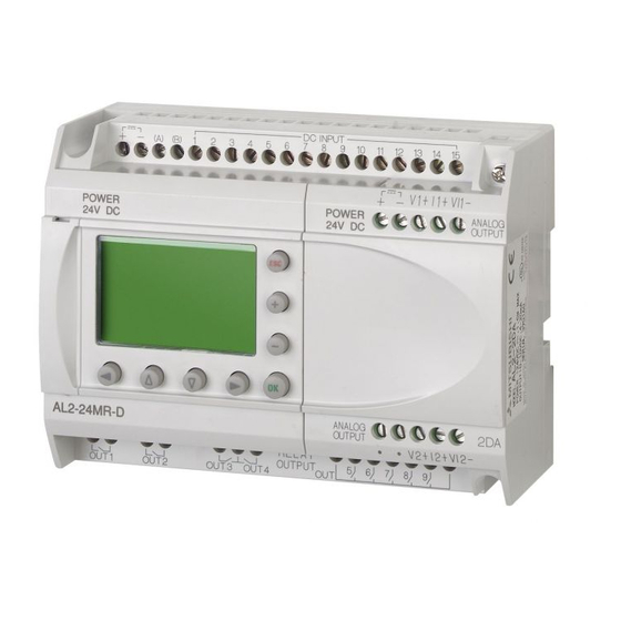
α Introduction 1 2 Simple Application Controllers Dimensions and Each Part Name Figure 1.1: Each Part Name ‚ „ ƒ 6 ( 0 . 2 4 " ) E 0 1 E 0 2 D C I N P U T ( A ) ( B ) †... -
Página 19: System Configuration
α Introduction 1 2 Simple Application Controllers System Configuration Figure 1.2: System Configuration Standard Connection to the Programming Softoware α Using Dedicated Protocol Series & Remote Maintenance (via Telephone Line) Normal Modem Normal Modem Personal computer - Programming Software (AL-PCS/WIN-E) - Dedicated protocol Remote Maintenance, e-Mail (via GSM) - e-Mail application... -
Página 20: Version Up List
α Introduction 1 2 Simple Application Controllers Version Up List α Table 1.6: History of 2 Series Version Description V1.00 First product Supports the following points. • AL2-2DA, AL2-2PT-ADP , AL2-2TC-ADP modules V2.00 • New function blocks AO [Analog output] and PID [PID control] •... -
Página 21: Specifications
α Specifications 2 2 Simple Application Controllers Specifications Note; • Refer to chapter 9 about specification of the AL2-ASI-BD. • Refer to chapter 11 about specification of the AL2-2DA. • Refer to chapter 12 about specification of the AL2-2PT-ADP . •... -
Página 22: Input Specification
α Specifications 2 2 Simple Application Controllers Input Specification Table 2.2: AC Input Specifications AC Input Specification Description main unit AL2-4EX-A2 I01 - I08 I09 - I15 EI1 - EI4 220 - 240V AC~, +10% -15%, Input Voltage 100 - 240V AC~, +10% -15%, 50/60 Hz 50/60 Hz 0.13mA / 120V AC~ 0.15mA / 120V AC~... - Página 23 α Specifications 2 2 Simple Application Controllers Table 2.4: Analog Input Specifications (Only AL2-***-D Type Unit) Description Analog Input Specification Number of Input Points 8 (I01 - I08) Analog Input Range 0 - 500 Resolution 9 bit, 20mV (10000/ 500mv) Conversion Speed Input Voltage 0 - 10V DC...
-
Página 24: Output Specification
α Specifications 2 2 Simple Application Controllers Output Specification Table 2.5: Relay Output Specifications Description Relay Specification Switched Voltage 250V AC~ or less, 30V DC or less AL2-14MR-* (O01 - O06) 8A/COM AL2-24MR-* (O01 - O04) Max. Resistive Load AL2-24MR-* (O05 - O09) 2A/point (4A/COM) AL2-4EYR (EO1 - EO4) 2A/point AL2-14MR-* (O01 - O06) -
Página 25: General Specification
α Specifications 2 2 Simple Application Controllers General Specification Table 2.7: Environmental and Electrical Specifications Description Specification Programming Method Function Block Program Capacity 200 Function Blocks or 5000 bytes Built in EEPROM (no battery backup required) or optional EEPROM Program Storage cassette (AL2-EEPROM-2) Device Backup 20 Days at 25°C / 77°F (by capacitor) - Página 26 α Specifications 2 2 Simple Application Controllers Table 2.7: Environmental and Electrical Specifications Description Specification Temperature for the Ball 75°C (167°F) Pressure Test EC Directive EMC, LVD Certifications UL/cUL Attestation of Conformity TÜV PRODUCT SERVICE UL 508 IEC 60730-1 EN 61010-1 Complies with EN 50081-1 EN 50082-1...
-
Página 27: Installation
α Installation 3 2 Simple Application Controllers Installation Installation Mounting Notes α 2 Series’ safe design means the user can install it almost anywhere but please take the following points into consideration. • Do not install in areas with excessive or conductive dust, corrosive or flammable gas, moisture or rain, excessive heat, regular impact shocks or excessive vibration. -
Página 28: Din Rail Mounting Of Main Unit
α Installation 3 2 Simple Application Controllers DIN RAIL Mounting of Main Unit Units can be snap mounted to 35mm DIN rail (DIN EN 50022). To release pull the spring loaded clips away from the rail and slide the unit off and up. 3.2.1 Installation Figure 3.2: Installation... -
Página 29: Direct Mounting Of Main Unit
α Installation 3 2 Simple Application Controllers Direct Mounting of Main Unit Figure 3.4: Direct Mounting 124.6 (4.91") 6 (0.24") 112.6 (4.43") 6 (0.24") Main Unit M4 Mounting Screw ENG-15... -
Página 30: Install Extension Module
α Installation 3 2 Simple Application Controllers Install Extension Module Caution; Disconnect all terminals from the power supply before removing the cover. Figure 3.5: Installation 1) Release screw ‘A’ and keep. D C I N P U T ( A ) ( B ) 2) Carefully remove the factory fitted expansion P O W E R... -
Página 31: Wiring
α Wiring 4 2 Simple Application Controllers Wiring Note; • Refer to chapter 9 when wiring the AL2-ASI-BD. • Refer to chapter 11 when wiring the AL2-2DA. • Refer to chapter 12 when wiring the AL2-2PT-ADP . • Refer to chapter 13 when wiring the AL2-2TC-ADP . Installation Wiring Notes α... -
Página 32: Wire Size
α Wiring 4 2 Simple Application Controllers Wire Size Wire of the Inputs and Outputs using the following wire. Strip the wire to the following length (See Table 4.1 and Figure 4.1). Please unscrew the terminal to its widest position before inserting a wire. -
Página 33: Power Supply
α Wiring 4 2 Simple Application Controllers Power Supply • When wiring AC supplies the “Live” cable should be connected to the “L” terminal and the “Neutral” cable should be connected to the “N” terminal. Do NOT connect the “Live” wire to the “N”... -
Página 34: Ac Power Supply And Input Wiring
α Wiring 4 2 Simple Application Controllers AC Power Supply and Input Wiring 4.4.1 AC Power Supply and Input Wiring Figure 4.3: AC Power Supply and Input Wiring Diagram "L" and "N" terminals are not reversible. & 1 2 3 4 5 6 INPUTS + Table 4.3: AC Power Supply and Input Wiring... -
Página 35: Dc Power Supply And Input Wiring
α Wiring 4 2 Simple Application Controllers DC Power Supply and Input Wiring 4.5.1 DC Power Supply and Source (“+” Common) Input Wiring Diagram Figure 4.5: DC Power Supply and Source (“+” Common) Input Wiring Diagram & 1 2 3 4 5 6 (A) (B) INPUTS , Table 4.5: DC Power Supply and Source (“+”... -
Página 36: Dc Power Supply And Sink ("-" Common) Input Wiring Diagram
α Wiring 4 2 Simple Application Controllers 4.5.3 DC Power Supply and Sink (“-” Common) Input Wiring Diagram Figure 4.7: DC Power Supply and Sink (”-” Common) Input Wiring Diagram & 1 2 3 4 5 6 (A) (B) INPUTS , Table 4.7: DC Power Supply and Sink (“-”... -
Página 37: Output Relay And Transistor Wiring
α Wiring 4 2 Simple Application Controllers Output Relay and Transistor Wiring 4.6.1 Relay Output Wiring Diagram main unit (AC and/or DC) Figure 4.9: Relay Output Wiring Diagram main unit (AC and/or DC) OUT1 OUT2 OUT3 OUT4 OUT5 OUT6 & &... -
Página 38: Relay Output Wiring Diagram Al2-4Eyr (Ac And/Or Dc)
α Wiring 4 2 Simple Application Controllers 4.6.2 Relay Output Wiring Diagram AL2-4EYR (AC and/or DC) Figure 4.10: Relay Output Wiring Diagram AL2-4EYR (AC and/or DC) & & & & Table 4.11: Relay Output Wiring AL2-4EYR (AC and/or DC) Ref. Item Description DC power supply Emergency stop... -
Página 39: Transistor Output (Source Or "+" Common Only) Wiring Diagram Al2-4Eyt
α Wiring 4 2 Simple Application Controllers 4.6.3 Transistor Output (Source or “+” Common Only) Wiring Diagram AL2-4EYT Figure 4.11: Transistor Output (Source/ “+” Common Only) Wiring Diagram AL2-4EYT EO1 EO2 EO3 EO4 & & & & Table 4.13: Transistor Output Wiring Ref. - Página 40 α Wiring 4 2 Simple Application Controllers MEMO ENG-26...
-
Página 41: Terminal Layout
α Terminal Layout 5 2 Simple Application Controllers Terminal Layout Note; • Refer to chapter 9 about terminal layout of the AL2-ASI-BD. • Refer to chapter 11 about terminal layout of the AL2-2DA. • Refer to chapter 12 about terminal layout of the AL2-2PT-ADP . •... - Página 42 α Terminal Layout 5 2 Simple Application Controllers Figure 5.4: AL2-24MR-D, DC Input, Relay Output (A) (B) 10 11 12 13 14 15 AL2-24MR-D OUT1 OUT2 OUT3 OUT4 Figure 5.5: AL2-4EX-A2, 220 - 240V AC Input COM(N) EI2 EI3 EI4 AL2-4EX-A2 Figure 5.6: AL2-4EX, DC Input AL2-4EX...
- Página 43 α Terminal Layout 5 2 Simple Application Controllers Figure 5.8: AL2-4EYT, Transistor Output AL2-4EYT EO3 EO4 ENG-29...
- Página 44 α Terminal Layout 5 2 Simple Application Controllers MEMO ENG-30...
-
Página 45: Al2-Eeprom-2
α AL2-EEPROM-2 6 2 Simple Application Controllers AL2-EEPROM-2 α The AL2-EEPROM-2 memory cassette is for use only with the 2 series controller (Model: AL2-**M*-*). Caution • Persons trained in the local and national electrical standards must replace the memory cassette. •... -
Página 46: Installation
α AL2-EEPROM-2 6 2 Simple Application Controllers Installation 1) Remove the cover or the memory cassette ‚ ƒ 2) Install on the cover or the memory cassette ‚ ENG-32... -
Página 47: Simple Application Controllers
α AL-232CAB 7 2 Simple Application Controllers AL-232CAB Introduction α α α The AL-232CAB is an RS-232C cable used to connect an series controller ( 2) and a personal computer that is running the programming software (AL-PCS/WIN-E). Note; • AL-232CAB cable cannot be used for any other applications. •... -
Página 48: Connected To Al-232Cab Cable
α AL-232CAB 7 2 Simple Application Controllers Connected to AL-232CAB cable Remove cover and memory cassette α • Be careful of personal safety when removing the 2 cover. Caution • Turn off the power supply when you install or detach the AL-232CAB cable. •... - Página 49 α AL-232CAB 7 2 Simple Application Controllers 2) Connecting the AL-232CAB cable 3) Removing the AL-232CAB cable 4) Installing on the cover or the memory cassette ‚ ENG-35...
- Página 50 α AL-232CAB 7 2 Simple Application Controllers MEMO ENG-36...
-
Página 51: Al2-Gsm-Cab
α AL2-GSM-CAB 8 2 Simple Application Controllers AL2-GSM-CAB Introduction α The AL2-GSM-CAB can be used to connect 2 Series Controllers to a normal or GSM modem. The AL2-GSM-CAB can transfer Short Message Service (SMS) data to a GSM modem for transmission to mobile phones and mail addresses or can facilitate remote monitoring functions and program transfers via normal modems. -
Página 52: System Configuration With Using Al2-Gsm-Cab
α AL2-GSM-CAB 8 2 Simple Application Controllers 8.1.2 System Configuration with using AL2-GSM-CAB Figure 8.2: System Configuration with AL2-GSM-CAB Using Dedicated Protocol α Series Remote Maintenance (Via Telephone Line) Normal Modem Normal Modem & Personal computer Remote Maintenance, E-Mail (Via GSM) - Programming Software (AL-PCS/WIN-E) Normal Modem... -
Página 53: Installation
• Put the cover back on after either installing or removing the AL2-GSM-CAB. • Under no circumstances will Mitsubishi Electric be liable or responsible for any consequential damage that may arise as a result of the installation or use of this equipment. - Página 54 α AL2-GSM-CAB 8 2 Simple Application Controllers Figure 8.4: Installation 1) Release screw ‘A’ and keep. D C I N P U T ( A ) ( B ) α P O W E R 2) Carefully remove the factory fitted 2 expansion 2 4 V D C E S C...
-
Página 55: Remote Maintenace With A Modem
α AL2-GSM-CAB 8 2 Simple Application Controllers Remote Maintenace with a Modem α Further information of the modem setup procedures can be found in the 2 Programming Manual. The programming software (AL-PCS/WIN-E) provides the easiest method to setup the modem. 8.3.1 Recommended Modems The following modems have been successfully tested. -
Página 56: Modem Setting
α AL2-GSM-CAB 8 2 Simple Application Controllers 8.3.3 Modem Setting 1) Setting of personal computer side Install the file for the setting of the attachment in the modem. α 2) Setting of 2 series side α The modem on the 2 series side is set by the ModemInit command of the main unit. - Página 57 α AL2-GSM-CAB 8 2 Simple Application Controllers Table 8.5: AT Command for GSM Modem Example Setting Setting Item Set content M20T Enable command echo Echo mode OFF Set number of ring before Enable automatic answering on the ring S0=2 automatically answering the call twice Set circuit data set ready (DSR) DSR always ON...
- Página 58 α AL2-GSM-CAB 8 2 Simple Application Controllers MEMO ENG-44...
-
Página 59: Al2-Asi-Bd
• Turn off the power supply when you install or remove the AL2-ASI-BD. • Replace the cover after removing the AL2-ASI-BD. • Under no circumstances will Mitsubishi Electric be liable or responsible for any consequential damage that may arise as a result of the installation or use of this equipment. -
Página 60: System Configuration
α AL2-ASI-BD 9 2 Simple Application Controllers 9.1.2 System Configuration Figure 9.2: System Configuration AS-interface Master AS-interface Slave Module (Sensor / Actuator) AS-interface Slave AS-interface AS-interface Slave AS-interface Slave α 2 Series Power Supply (Sensor / Actuator) (Sensor / Actuator) + AL2-ASI-BD) Specifications For general specifications please refer to the Chapter 2. -
Página 61: Wiring & Installation
α AL2-ASI-BD 9 2 Simple Application Controllers Wiring & Installation 9.3.1 Installation Caution Disconnect all terminals from the power supply before removing the cover. Figure 9.3: Installation 1) Release screw ‘A’ and keep. D C I N P U T ( A ) ( B ) 2) Carefully remove the factory fitted expansion... -
Página 62: Wiring
α AL2-ASI-BD 9 2 Simple Application Controllers 9.3.2 Wiring Use the AS-interface flat cable (yellow) for connecting the AL2-ASI-BD to the network. When connecting AS-interface cable to the module, tighten communication connector pin screws to a torque of 0.5 ~ 0.6N·m. Figure 9.4: Wiring AS-interface Flat cable (Yellow) ASI+... -
Página 63: Dcf77 Radio Clock
α DCF77 Radio Clock 10 2 Simple Application Controllers DCF77 Radio Clock α The DCF77 function for the 2 series provides automatic setup of the RTC (Real Time Clock) from receiving and decoding DCF77 time information that is broadcast over the radio signal 77.5kHz from Frankfurt/Germany. -
Página 64: System Configuration
α DCF77 Radio Clock 10 2 Simple Application Controllers 10.2 System Configuration Figure 10.1: DCF 77 Antenna* NT DCF 77 α α α 2 Series 2 Series 2 Series Power-pack* * Manufactured by Theben AG α 2 series must use a Theben DCF77 antenna and at least one Theben device to power α... -
Página 65: Wiring
α DCF77 Radio Clock 10 2 Simple Application Controllers Table 10.4: Applicable Version PLC Type Applicable version α 2 Series (DC Version only) V2.00 or later VLS Software V2.30 or later Caution α • The AC version of the 2 series cannot be used to receive DCF77 radio signals. α... -
Página 66: Dcf77 Setup From Alpha Display
α DCF77 Radio Clock 10 2 Simple Application Controllers 10.4.2 DCF77 Setup from Alpha display 1) From the TopMenu, scroll to “Clockset” and press the “OK” key. From the options that appear, scroll to “Radioclock” and press the “OK” key. Only one option appears if the Radioclock has not been activated. -
Página 67: Automatically Start
α DCF77 Radio Clock 10 2 Simple Application Controllers 8) Press the “OK” or “ESC” keys to preform an execute or cancel operation. M a n u a l S t o p A c t E S C Note α... - Página 68 α DCF77 Radio Clock 10 2 Simple Application Controllers MEMO ENG-54...
-
Página 69: Al2-2Da
(integral with sensors or actuators), these users should follow those manufacturers installation requirements. • Mitsubishi Electric recommends that shielded cables should be used. If NO other EMC protection is provided, then users may experience temporary errors not exceeding +10%/-10% in very heavy industrial areas. -
Página 70: Introduction
α AL2-2DA 11 2 Simple Application Controllers 11.1 Introduction α The AL2-2DA Analog Output Module (hereafter called "AL2-2DA") is to be installed onto an Series Controller and should be used to convert a digital value to a voltage (0~10V) or current (4~20mA) analog output signal. -
Página 71: Specification
α AL2-2DA 11 2 Simple Application Controllers 11.2 Specification Table 11.2: Power Specification Item Content Supplied from the α2 Main Unit Integrated Power Supply External Supply for Analog output 24V DC External Supply current consumption 70mA Table 11.3: Hardware Specification Specification Item Voltage... -
Página 72: Wiring & Installation
α AL2-2DA 11 2 Simple Application Controllers 11.3 Wiring & Installation 11.3.1 Installation Caution • Disconnect all terminals from the power supply before installing the AL2-2DA. • Do not install in areas with: excessive or conductive dust, corrosive or flammable gas, moisture or rain, excessive heat, regular impact shocks or excessive vibration. -
Página 73: Wiring
α AL2-2DA 11 2 Simple Application Controllers 11.3.2 Wiring Caution • Turn off the Power before performing any wiring operations. • The Output cables should not be run through the same multi core cable or share the same wire. • The wire should be used as a single cable or the multi core wires (can be used with a crimp terminal) should be carefully twisted together. -
Página 74: Applicable Error Checks
α AL2-2DA 11 2 Simple Application Controllers 11.3.3 Applicable Error checks 1) If an External power supply error (M16) occurs: Check the “+” and “-” connections to the AL2-2DA for correct wiring and installation procedures. Check the original Power Supply source for 24V DC operation. ENG-60... -
Página 75: Al2-2Pt-Adp
(integral with sensors or actuators), these users should follow those manufacturers installation requirements. • Mitsubishi Electric recommends that shielded cables should be used. If NO other EMC protection is provided, then users may experience temporary errors not exceeding +10%/-10% in very heavy industrial areas. -
Página 76: Introduction
α AL2-2PT-ADP 12 2 Simple Application Controllers 12.1 Introduction ° The AL2-2PT-ADP should be used convert PT100 Temperature input (-50 ~ 200 C) to a voltage equivalent (0 ~ 10V) for direct use in the main unit. 12.1.1 External Dimensions Figure 12.1:External Dimensions Unit:mm (inches) Table 12.1:... -
Página 77: Specification
α AL2-2PT-ADP 12 2 Simple Application Controllers 12.3 Specification Table 12.3: General Specification Item Content Operating Temperature (-25) ~ 55°C / (-13) ~ 131°F Storage Temperature (-30) ~70°C / (-22) ~ 158°F Humidity 35 ~ 85% Relative humidity, no condensation Conforms to IEC 68-2-6;... - Página 78 α AL2-2PT-ADP 12 2 Simple Application Controllers Table 12.6: Hardware Specifications Specification Item Centigrade (°C) Fahrenheit (°F) Digital D igital +2075 +4055 +2000 +207.5°C +3920 +405.5°F Input Characteristics -50°C -58°F Temperature T emperature +200°C +392°F -500 -580 -57.5°C -71.5°F (PT 100) (PT 100) -575 -715...
-
Página 79: Wiring And Installation
α AL2-2PT-ADP 12 2 Simple Application Controllers 12.4 Wiring and Installation 12.4.1 Installation Caution • Do not install in areas with: excessive or conductive dust, corrosive or flammable gas, moisture or rain, excessive heat, regular impact shocks or excessive vibration. •... -
Página 80: Wiring
α AL2-2PT-ADP 12 2 Simple Application Controllers 12.4.2 Wiring Caution • Please use an isolated Power supply and turn off the Power before any wiring operation is performed. • Input and Output cables should not be run through the same multi core cable or share the same wire. -
Página 81: Choosing A Temperature Scale
α AL2-2PT-ADP 12 2 Simple Application Controllers 12.4.3 Choosing a Temperature Scale 1) Turn on the power to the α2 controller and select “Others...” from the TopMenu. T o p M e n u C l o c k s e t L A N G U A G E O t h e r s . -
Página 82: Offset Adjustment
α AL2-2PT-ADP 12 2 Simple Application Controllers 12.4.4 Offset Adjustment Note If Gain adjustment is complete, then step 3 ~ 7 are not needed. 1) To begin the calibration for channel 1, turn off the power to the α2 controller and the AL2- 2PT-ADP, remove the temperature sensor. -
Página 83: Gain Adjustment
α AL2-2PT-ADP 12 2 Simple Application Controllers 4) Configure the input for temperature sensing with the AL2-2PT-ADP module by selecting “Mode” and choosing “PT100” from the following screen. I 0 1 I 0 1 M o d e N o r m a l P T 1 0 0 5) After setting the mode to “PT100”, select “Calibrate”... - Página 84 α AL2-2PT-ADP 12 2 Simple Application Controllers 2) Remove the top cover from the jumper area and move the jumper to the pins labeled 200°C as in “Hardware Setup” below. Figure 12.7: AL2-2PT-ADP Gain Adjustment Hardware Setup Controller Setup C a l i b r a t e - 5 0 °...
-
Página 85: Fine Offset Adjust
α AL2-2PT-ADP 12 2 Simple Application Controllers 12.4.6 Fine Offset Adjust The fine adjust should only be performed after both Gain and Offset Adjusts have been performed. 1) From the TopMenu, select “Others...” T o p M e n u C l o c k s e t L A N G U A G E O t h e r s . -
Página 86: Applicable Error Checks
α AL2-2PT-ADP 12 2 Simple Application Controllers 12.4.7 Applicable Error checks In the event that the input voltage is greater than 11 V or equal to 0V the following system flags will be set. Table 12.8: 0: Normal 1: Defect at I01 0: Normal 1: Defect at I02 0: Normal... -
Página 87: Al2-2Tc-Adp
(integral with sensors or actuators), these users should follow those manufacturers installation requirements. • Mitsubishi Electric recommends that shielded cables should be used. If NO other EMC protection is provided, then users may experience temporary errors not exceeding +3%/- 3% in very heavy industrial areas. -
Página 88: Introduction
α AL2-2TC-ADP 13 2 Simple Application Controllers 13.1 Introduction The AL2-2TC-ADP should be used convert thermocouple sensor (K type) temperature input to 0~10V voltage analog signal for use in the main unit. 13.1.1 External Dimensions Figure 13.1:External Dimensions Unit:mm (inches) Table 13.1: Item Description... -
Página 89: Specification
α AL2-2TC-ADP 13 2 Simple Application Controllers 13.3 Specification Table 13.3: General Specification Item Content Operating Temperature (-25) ~ 55°C / (-13) ~ 131°F Storage Temperature (-30) ~70°C / (-22) ~ 158°F Humidty 35 ~ 85% Relative humidity, no condensation Conforms to IEC 68-2-6;... - Página 90 α AL2-2TC-ADP 13 2 Simple Application Controllers Table 13.6: Hardware Specifications Specification Item Centigrade (°C) Fahrenheit (°F) Digital Digital +470 +878 +450 +470°C +842 +878°F Input Characteristics -50°C -58°F Temperature +450°C Temperature +842°F -70°C (TypeK) -94°F (K-Type) Table 13.7: Software Specification Item Content “ON”...
-
Página 91: Wiring And Installation
α AL2-2TC-ADP 13 2 Simple Application Controllers 13.4 Wiring and Installation 13.4.1 Installation Caution • Do not install in areas with: excessive or conductive dust, corrosive or flammable gas, moisture or rain, excessive heat, regular impact shocks or excessive vibration. •... -
Página 92: Wiring
α AL2-2TC-ADP 13 2 Simple Application Controllers 13.4.2 Wiring Caution • Please use an isolated Power supply and turn off the Power before any wiring operation is performed. • Input and Output cables should not be run through the same multi core cable or share the same wire. -
Página 93: Choosing A Temperature Scale
α AL2-2TC-ADP 13 2 Simple Application Controllers 13.4.3 Choosing a Temperature Scale 1) Turn on the power to the α2 controller and select “Others...” from the TopMenu. T o p M e n u C l o c k s e t L A N G U A G E O t h e r s . -
Página 94: Offset Adjustment
α AL2-2TC-ADP 13 2 Simple Application Controllers 13.4.4 Offset Adjustment Note If Gain adjustment is complete, then step 3 ~ 7 are not needed. 1) To begin the offset calibration for channel 1, turn off the power to the α2 controller and the AL2-2TC-ADP and remove the temperature sensor. -
Página 95: Gain Adjustment
α AL2-2TC-ADP 13 2 Simple Application Controllers 4) Configure the input for temperature sensing with the AL2-2TC-ADP module by selecting “Mode” and choosing “TC” from the following screen I 0 1 I 0 1 M o d e N o r m a l P T 1 0 0 5) After setting the mode to “TC”, select “Calibrate”... - Página 96 α AL2-2TC-ADP 13 2 Simple Application Controllers 2) Remove the top cover from the jumper area and move the jumper to the pins labeled 450°C as in “Hardware Setup” below. Figure 13.7: AL2-2TC-ADP Gain Adjustment Hardware Setup Controller Setup C a l i b r a t e - 5 0 °...
-
Página 97: Fine Offset Adjust
α AL2-2TC-ADP 13 2 Simple Application Controllers 13.4.6 Fine Offset Adjust The fine adjust should only be performed after both Gain and Offset Adjusts have been performed. 1) From the TopMenu, select “Others...” T o p M e n u C l o c k s e t L A N G U A G E O t h e r s . -
Página 98: Applicable Error Checks
α AL2-2TC-ADP 13 2 Simple Application Controllers 13.4.7 Applicable Error Checks 1) In the event that the input voltage is greater than 11 V or equal to 0V the following system flags will be set. Table 13.8: 0: Normal 1: Defect at I01 0: Normal 1: Defect at I02 0: Normal... -
Página 99: Key, System Bit And Function Block Lists
α Key, System Bit and Function Block Lists 14 2 Simple Application Controllers Key, System Bit and Function Block Lists 14.1 Key Lists The following table is the keys to use operation in the Menu and user program. Further α information can be found in 2 Programming Manual. -
Página 100: System Bit Lists
α Key, System Bit and Function Block Lists 14 2 Simple Application Controllers 14.2 System Bit Lists There is the system bit controlled by system and the control bit to control from user program. 14.2.1 System Bit Lists Table 14.2: System Bit Lists System Bit Description Always “ON”... -
Página 101: Control Bit Lists
α Key, System Bit and Function Block Lists 14 2 Simple Application Controllers 14.2.2 Control Bit Lists Table 14.3: Control Bits Control Bit Description Disconnected to AS-interface network OFF: Connect to AS-interface network The back light is “OFF” in LCD. OFF: The back light is controlled by the “Light Time”... -
Página 102: Function Block Lists
α Key, System Bit and Function Block Lists 14 2 Simple Application Controllers 14.3 Function Block Lists α Further information for function blocks can be found in the 2 Series Programming Manual. Table 14.4: Function Block Lists Function Block Memory Consumption Description Name... - Página 103 α Key, System Bit and Function Block Lists 14 2 Simple Application Controllers Table 14.4: Function Block Lists Function Block Memory Consumption Description Name Symbol (Byte) The signal input frequency (On/Off) is measured for a set length of time. The frequency is compared to a Speed Detect value range and the Output is turned ON/OFF according to the result.
- Página 104 α Key, System Bit and Function Block Lists 14 2 Simple Application Controllers Table 14.4: Function Block Lists Function Block Memory Consumption Description Name Symbol (Byte) Control which Display screen appears on the LCD. This function block can only be set in the AL-PCS/WIN- Control E software.
-
Página 105: Diagnostics
α Diagnostics 15 2 Simple Application Controllers Diagnostics Caution • Do not touch the terminal while energized. This might cause an equipment malfunction or an electric shock. Caution • Supply correctly rated power. When a power supply different from the ratings is supplied, this product might be damaged or cause a fire. -
Página 106: Input Status Error
α Diagnostics 15 2 Simple Application Controllers 15.1 Input Status Error α Place the 2 controller in the Stop mode. Cycle the power to the equipment connected to the input terminals and check if the input status is displayed correctly. If it is not correctly displayed, check the points below. -
Página 107: Top Menu Is Not Displayed
α Diagnostics 15 2 Simple Application Controllers 15.3 TOP MENU is not Displayed The menu key should be operated to access the Top Menu. Push the keys “OK” and “ESC” at the same time. If the menu call key is not set, use either the programming software to the Stop mode or do the forced stop operation. -
Página 108: Cannot Enter Run Mode
Switch from “TopMenu” to the Run mode after deleting the program. a) The program again and switch to Run mode. b) Consult a Mitsubishi Distributor when unable to switch to the RUN mode. 15.5 Incorrect Clock Data Confirm the following item. -
Página 109: Cannot Use An Operation Key
If the steps outlined in instructions (1) - (5) below can be performed, the keys are operating properly. Please check if the key(s) are used in the program. 1) Place the controller in the Stop mode. Consult a Mitsubishi Distributor when the Stop mode cannot be entered. -
Página 110: Incorrect Lcd Display
Check the following items. 1) The character is displayed in reverse and the entire screen is black. α Consult a Mitsubishi Distributor when the above error occurs. The 2 controller display has been damaged. 2) An Unexpected Display Configuration is Shown When the display does not appear as expected, please check the following points in the program. -
Página 111: 15.10 Cannot Communicate With The As-Interface Master Module
α Diagnostics 15 2 Simple Application Controllers 15.10 Cannot Communicate with the AS-interface Master Module Check the following items. Notes on use α • Use the expansion board or the connector cover while power is supplied to the 2 series controller. -
Página 112: 15.11 Cannot Communicate With Al-Pcs/Win-E
α Diagnostics 15 2 Simple Application Controllers 15.11 Cannot Communicate with AL-PCS/WIN-E. Check the following items. Notes on use Use the memory cassette and the communication cable or the connector cover while installed without fail. It causes the electric shock and the breakdown. 1) Check cable (AL-232CAB) connection. -
Página 113: Hardware-Handbuch
α 2-Steuerung HARDWARE-HANDBUCH... - Página 114 Wenn während der Installation Fragen auftreten, ziehen Sie auf jeden Fall eine Elektrofachkraft zu Rate, die mit den lokalen und nationalen elektrotechnischen Bestimmungen vertraut ist. Setzen Sie sich mit dem nächstliegenden Händler von MITSUBISHI ELECTRIC in Verbindung, wenn Sie Unterstützung bei der α...
- Página 115 α Steuerung α 2-Steuerung Hardware-Handbuch Nummer: JY992D97301 Revision: Datum: 10/2003 GER-i...
- Página 116 α Steuerung GER-ii...
- Página 117 Steuerung Bitte, nehmen Sie sich einen Augenblick Zeit... Mitsubishi Electric ist weltweit für sein Bestreben bekannt, die industrielle Automation weiter zu entwickeln und zu erleichtern. Dabei wird gerade vom Anwender der Aufwand für eine einwandfreie technische Dokumentation des öfteren unterschätzt. Deshalb sind wir ganz besonders auf Sie und Ihre Meinung angewiesen, damit alle Produkte und Dokumentationen von Mitsubishi auch in Zukunft dem schnell ansteigenden Fortschritt gerecht werden können.
- Página 118 α Steuerung GER-iv...
- Página 119 α Steuerung α Sicherheitsrichtlinien für den Anwender und Schutzmaßnahmen für die Steuerung α Dieses Handbuch beinhaltet Informationen für den Gebrauch der 2 Steuerung. Das Handbuch wurde für geschultes und kompetentes Personal erstellt. Hierbei wird für die Qualifizierung folgende Definition zugrunde gelegt: a) Jeder Techniker, der Anlagen der Automatisierungstechnik unter Einbeziehung des Produktes plant, projektiert und errichtet, sollte diesbezüglich ausreichende Kenntnisse besitzen.
- Página 120 Gewährleistung übernommen werden. MITSUBISHI ELECTRIC übernimmt keine Verantwortung für eine Produktanwendung, die sich auf die dargestellten Beispiele bezieht. • Bitte wenden Sie sich bei Anwendungen, bei denen lebensgefährliche Zustände auftreten können oder die eine hohe Verfügbarkeit erforder n, an Ihre Mitsubishi Electric Niederlassung. Liste weiterer Handbücher Bezeichnung Handbuch Nr..
- Página 121 α Steuerung Abkürzungen In diesem Handbuch werden die folgenden Abkürzungen verwendet: • Die AL-PCS/WIN-E-Programmier-Software wird entweder mit AL-PCS/WIN-E oder „Programmier-Software“ bezeichnet. α α α • Für die 2-Steuerung werden die Begriffe „ 2-Serie“, „ 2-Steuerung“ oder „Grundgerät“ verwendet. • Funktionsblöcke werden mit „FB“ abgekürzt. •...
- Página 122 α Steuerung GER-viii...
- Página 123 α 2-Steuerung Inhaltsverzeichnis Sicherheitsrichtlinien ..............GER-v 1. Einleitung..................GER-1 α 1.1 Besonderheiten der 2-Steuerung:............... GER-2 1.2 Verfügbare Modelle ..................GER-3 1.3 Abmessungen und Bedienungselemente ............GER-4 1.4 Systemkonfiguration ..................GER-5 1.5 Liste der Versionen..................GER-5 1.6 Programmier-Software .................. GER-6 2. Technische Daten ................GER-7 2.1 Spannungsversorgung ..................
- Página 124 α 2-Steuerung 5. Klemmenbelegung ...............GER-27 6. AL2-EEPROM-2 ................GER-31 6.1 Installation ....................GER-32 7. AL-232CAB ...................GER-33 7.1 Einleitung ..................... GER-33 7.1.1 Abmessungen ....................GER-33 7.2 Verbindung mit dem Kabel AL-232CAB ............GER-34 8. AL2-GSM-CAB ................GER-37 8.1 Einleitung ..................... GER-37 8.1.1 Abmessungen ....................GER-37 8.1.2 Systemkonfiguration bei Verwendung des AL2-GSM-CAB.......
- Página 125 α 2-Steuerung 11.AL2-2DA..................GER-55 11.1 Übersicht ..................... GER-56 11.1.1 Äußere Abmessungen..................GER-56 11.1.2 Systemkonfiguration ..................GER-56 11.2 Technische Daten..................GER-57 11.3 Installation und Verdrahtung................ GER-58 11.3.1 Installation ......................GER-58 11.3.2 Verdrahtung....................... GER-59 11.3.3 Fehlerdiagnose....................GER-60 12.AL2-2PT-ADP................GER-61 12.1 Übersicht ..................... GER-62 12.1.1 Äußere Abmessungen..................GER-62 12.2 Systemkonfiguration ..................
- Página 126 α 2-Steuerung 15.Fehleranalyse................GER-91 15.1 Eingangsstatusfehler ................... GER-92 15.2 Ausgangsstatusfehler .................. GER-92 15.3 Hauptmenü wird nicht angezeigt ..............GER-93 15.4 Umschaltung in den Run-Modus nicht möglich ........... GER-94 15.5 Falsche Uhrzeit.................... GER-94 15.6 Das “?” erscheint im Display................ GER-94 15.7 Die Funktionstasten können nicht verwendet werden ......... GER-95 15.8 Falsche LCD-Anzeige..................
-
Página 127: Einleitung
- Regulierung der Luftzirkulation in Viehställen und Treibhäusern α 2-Steuerung ist nicht für die folgenden Anwendungsmöglichkeiten entwickelt worden. Für weitere Informationen wenden Sie sich an einen Mitsubishi-Vertragspartner. - Anwendungen, die höchste Zuverlässigkeit erfordern. Dieses sind z.B. Nuklear- technologie, Schienenverkehr, Luftfahrt, Fahrzeuge mit Verbrennungsmotoren und medizinische Geräten. -
Página 128: Besonderheiten Der Α 2-Steuerung
α Einleitung 1 Steuerung α Besonderheiten der 2-Steuerung: 1) Informations- und Funktionsblockdaten-Anzeige α 2-Steuerung kann den Funktionszustand und die Alarmsignale visuell auf einer LCD- Anzeige darstellen. Die folgenden Informationen können über die Funktionsblockanzeige dargestellt werden. Die Werte angezeigter Timer und Counter können im RUN-Modus eingestellt werden. -
Página 129: Verfügbare Modelle
α Einleitung 1 Steuerung 10)Eingebauter EEPROM-Speicher Der eingebaute EEPROM-Speicher macht eine Batterie für die Datensicherung bei Stromausfall überflüssig. 11)Unterstützung von 6 Sprachen α 2-Steuerung unterstützt 6 Sprachen für die Bildschirmausgabe: Englisch, Deutsch, Französisch, Italienisch, Spanisch und Schwedisch. Die Sprache kann im Hauptmenü ausgewählt werden. -
Página 130: Abmessungen Und Bedienungselemente
α Einleitung 1 Steuerung Abmessungen und Bedienungselemente Abbildung 1.1: Bedienungselemente ‚ „ ƒ E 0 1 E 0 2 D C I N P U T ( A ) ( B ) † P O W E R 2 4 V D C E S C …... -
Página 131: Systemkonfiguration
α Einleitung 1 Steuerung Systemkonfiguration Abbildung 1.2: Systemkonfiguration S ta n d a rd ve rb in d u n g zu r P ro g ra m m ie r-S o ftw a re α V e rw e n d u n g d e s e rw e ite rte n P ro to k o lls S e rie &... -
Página 132: Programmier-Software
α Einleitung 1 Steuerung Programmier-Software Tabelle 1.7: Verwendbare Programmier-Software α Version der Version der Programm-Software (AL-PCS/WIN-E) Steuerung V1.00 V2.00 oder höher V2.00 V2.30 oder höher Anmerkung α • Frühere AL-PCS/WIN-E-Versionen als V2.00 werden von der 2-Steuerung nicht unterstützt. • Verwenden Sie die Erweiterungsmodule und Adapter AL-2DA, AL2-2PT-ADP und AL2- 2TC-ADP nicht zusammen mit AL-PCS/WIN-E Software mit einer niedrigeren Versionen als V2.30 GER-6... -
Página 133: Technische Daten
α Technische Daten 2 Steuerung Technische Daten Anmerkung • Die technischen Daten des AL2-ASI-BD finden Sie in Kapitel 9. • Die technischen Daten des AL2-2DA finden Sie in Kapitel 11. • Die technischen Daten des AL2-2PT-ADP finden Sie in Kapitel 12. •... -
Página 134: Eingänge
α Technische Daten 2 Steuerung Eingänge Tabelle 2.2: Technische Daten der AC-Eingänge Technische Daten Beschreibung Hauptmodul AL2-4EX-A2 I01–I08 I09–I15 EI1–EI4 220–240V AC, +10% -15%, Eingangsspannung 100–240V AC, +10% -15%, 50/60 Hz 50/60 Hz 0,13 mA/120V AC 0,15 mA/120V AC 7,5 mA / 240V AC 50Hz Eingangsstrom 9,0 mA / 240V AC 60Hz 0,25 mA/240V AC... - Página 135 α Technische Daten 2 Steuerung Tabelle 2.4: Technische Daten der analogen Eingänge (Nur Typ AL2-***-D) Beschreibung Technische Daten der analogen Eingänge Anzahl der analogen 8 (I01–I08) Eingänge Analogeingangsbereich 0–500 Auflösung 9 bit, 20 mV (10V / 500) Wandler- 8 ms geschwindigkeit Eingangsspannung 0–10 V DC...
-
Página 136: Ausgänge
α Technische Daten 2 Steuerung Ausgänge Tabelle 2.5: Technische Daten der Relais-Ausgänge Beschreibung Technische Daten Einschaltspannung 250V AC oder weniger, 30V DC oder weniger AL2-14MR-* (O01–O06) 8 A / Gesamt AL2-24MR-* (O01–O04) Max. ohmsche Last AL2-24MR-* (O05–O09) 2 A / Klemme (4 A / Gesamt) AL2-4EYR (EO1–EO4) 2 A / Klemme AL2-14MR-* (O01–O06) -
Página 137: Umgebungsbedingungen
α Technische Daten 2 Steuerung Umgebungsbedingungen Tabelle 2.7: Umgebungsbedingungen Beschreibung Technische Daten Programmiermethode Funktionsblock-Methode Programmkapazität 200 Funktionsblöcke oder 5000 Bytes EEPROM (keine Batterie erforderlich) oder optionale EEPROM-Kassette Programmspeicherung (AL2-EEPROM-2) Operandensicherung 20 Tage bei 25°C ( Kondensator ) Echtzeituhr-Backup ( Kondensator ) 20 Tage bei 25°C Genauigkeit Echtzeituhr 5 s/Tag... - Página 138 α Technische Daten 2 Steuerung Tabelle 2.7: Umgebungsbedingungen Beschreibung Technische Daten Temperatur für den 75°C Balldrucktest EC-Richtlinie EMC, LVD Zertifizierungen UL/cUL Konformitäts- TÜV PRODUCT SERVICE bescheinigung UL 508 IEC 60730-1 EN 61010-1 Tests EN 50081-1 EN 50082-1 EN 61000-6-2 4 Zeilen mit je 12 Zeichen, Run-Modus, Passwortschutz, Statustabelle und LCD-Anzeige Funktionsblock-Übersicht während der Programmierung *1 AL2-ASI-BD entspricht nicht diesen Standards.
-
Página 139: Installation
α Installation 3 Steuerung Installation Installationshinweise α 2-Steuerung wurde so konzipiert, dass sie unter Berücksichtigung folgender Einschränkungen nahezu überall eingesetzt werden kann: • Die Geräte dürfen den folgenden Umgebungsbedingungen nicht ausgesetzt werden: Umgebungen mit einem hohen Grad an leitfähigen Stäuben, Korrosion, entzündbaren Gasen, Feuchtigkeit, Regen, direkte Sonnenbestrahlung, große Hitze, starke Schockwellen und Vibrationen. -
Página 140: Montage Auf Einer Din Befestigungsschiene
α Installation 3 Steuerung Anmerkung • Wenn sie das AL2-EEPROM-2 installieren oder entfernen, beachten Sie bitte Kapitel 6. • Wenn sie das AL-232CAB installieren oder entfernen, beachten Sie bitte Kapitel 7. • Wenn sie das AL2-GSM-CAB installieren oder entfernen, beachten Sie bitte Kapitel 8. •... -
Página 141: Direktmontage
α Installation 3 Steuerung Direktmontage Abbildung 3.4: Direktmontage 124.6 112.6 S teuerung M 4 M ontag eschraube GER-15... -
Página 142: Installation Der Erweiterungsmodule
α Installation 3 Steuerung Installation der Erweiterungsmodule Achtung Trennen Sie alle Anschlüsse von der Spannungsversorgung, bevor Sie die Abdeckung entfernen. Abbildung 3.5: Installation 1) Lösen Sie die Schraube ‘A’. D C I N P U T ( A ) ( B ) P O W E R 2) Entfernen Sie vorsichtig die Abdeckung des 2 4 V D C... -
Página 143: Verdrahtung
α Verdrahtung 4 Steuerung Verdrahtung Anmerkung • Die Verdrahtung des AL2-ASI-BD ist im Kapitel 9 beschrieben. • Die Verdrahtung des AL2-2DA ist im Kapitel 11 beschrieben. • Die Verdrahtung des AL2-2PT-ADP ist im Kapitel 12 beschrieben.. • Die Verdrahtung des AL2-2TC-ADP ist im Kapitel 13 beschrieben. Hinweise zur Installationsverdrahtung α... -
Página 144: Kabelgröße Und Spezifikationen
α Verdrahtung 4 Steuerung Kabelgröße und Spezifikationen Für die Verdrahtung der Ein- und Ausgänge verwenden Sie bitte ausschließlich folgende Kabeltypen. Entfernen Sie die Isolierung der Kabelenden entsprechend der Angaben in der folgenden Tabelle (Siehe Tabelle 4.1 und Abbildung 4.1). Lösen Sie die Klemmschraube, bevor Sie ein Kabel anschliessen. -
Página 145: Spannungsversorgung
α Verdrahtung 4 Steuerung Spannungsversorgung • Beim Anschluss einer Wechselspannung (AC) muss der L-Leiter an die L-Klemme und der N-Leiter an die N-Klemme angeschlossen werden. Der L-Leiter darf niemals an die N-Klemme angeschlossen werden, weil dies für den Benutzer beim Einschalten des Gerätes zu einem lebensgefährlichen Stromschlag führen kann. -
Página 146: Ac-Spannungsversorgung Und Eingangsverdrahtung
α Verdrahtung 4 Steuerung AC-Spannungsversorgung und Eingangsverdrahtung 4.4.1 AC-Spannungsversorgung und Eingangsverdrahtung Abbildung 4.3: AC-Spannungsversorgungs und Eingangsschaltung Die Klemmen L und N duerfen nicht vertauscht werden. & 1 2 3 4 5 6 INPUTS Tabelle 4.3: AC-Spannungsversorgung und Eingangsverdrahtung Beschreibung AC-Spannungsversorgung: 100–240 V AC 50/60 Hz Schaltkreis-Schutzgerät Überlastschutz max. -
Página 147: Dc-Spannungsversorgung Und Eingangsverdrahtung
α Verdrahtung 4 Steuerung DC-Spannungsversorgung und Eingangsverdrahtung 4.5.1 DC-Spannungsversorgung und Source Eingangsverdrahtung (gemeinsamer “+” Pol) Abbildung 4.5: DC-Spannungsversorgung und Source Eingangsverdrahtung (gemeinsamer “+” Pol) & 1 2 3 4 5 6 (A) (B) INPUTS , Tabelle 4.5: DC-Spannungsversorgung und Source Eingangsverdrahtung (gemeinsamer “+”... -
Página 148: Dc-Spannungsversorgung Und Sink Eingangsverdrahtung (Gemeinsame Masse)
α Verdrahtung 4 Steuerung 4.5.3 DC-Spannungsversorgung und Sink Eingangsverdrahtung (gemeinsame Masse) Abbildung 4.7: DC-Spannungsversorgung und Sink Eingangsverdrahtung (gemeinsame Masse) & 1 2 3 4 5 6 (A) (B) INPUTS , Tabelle 4.7: DC-Spannungsversorgung und Sink Eingangsverdrahtung (gemeinsame Masse) Beschreibung DC-Spannungsversorgung: 24 V DC Schaltkreis-Schutzgerät Überlastschutz max. -
Página 149: Relais-/Transistor-Ausgangsverdrahtung
α Verdrahtung 4 Steuerung Relais-/Transistor-Ausgangsverdrahtung 4.6.1 Relaisausgangsverdrahtung Hauptmodul (AC und/oder DC) Abbildung 4.9: Relaisausgangs-Schaltdiagramm Hauptmodul (AC und/oder DC) OUT1 OUT2 OUT3 OUT4 OUT5 OUT6 & & & & & & Tabelle 4.9: Relaisausgangsverdrahtung Hauptmodul (AC und/oder DC) Beschreibung α 2-Steuerung Voneinander isolierte Ausgänge Ausgangsgeräte Sicherung (siehe Tabelle 4.10) -
Página 150: Relaisausgangsverdrahtung Al2-4Eyr (Ac Und/Oder Dc)
α Verdrahtung 4 Steuerung 4.6.2 Relaisausgangsverdrahtung AL2-4EYR (AC und/oder DC) Abbildung 4.10: Relaisausgangsverdrahtung AL2-4EYR (AC und/oder DC) & & & & Tabelle 4.11: Relaisausgangsverdrahtung AL2-4EYR (AC und/oder DC) Beschreibung DC-Spannung NOT-AUS-Schalter Sicherung (≤ 3 A) Voneinander isolierte Ausgänge Ausgangsgeräte AC-Spannung Tabelle 4.12: Relaisausgang Schutzschaltung Anzahl der Schaltkreis-Schutz... -
Página 151: Al2-4Eyt Transistor-Ausgangsverdrahtung (Nur Source )
α Verdrahtung 4 Steuerung 4.6.3 AL2-4EYT Transistor-Ausgangsverdrahtung (nur Source <gemeinsamer “+” Pol>) Abbildung 4.11: AL2-4EYT Transistor-Ausgangsverdrahtung (nur Source <gemeinsamer “+” Pol>) EO1 EO2 EO3 EO4 & & & & Tabelle 4.13: Transistor-Ausgangsverdrahtung Beschreibung DC-Spannungsversorgung für Ausgänge, 24 V DC NOT-AUS-Schalter Schaltkreis-Schutzgerät (siehe Table 4.14) Ausgangsklemmen Ausgangsgeräte... - Página 152 α Verdrahtung 4 Steuerung MEMO GER-26...
-
Página 153: Klemmenbelegung
α Klemmenbelegung 5 Steuerung Klemmenbelegung Anmerkung • Die Klemmenbelegung des AL2-ASI-BD ist in Kapitel 9 beschrieben. • Die Klemmenbelegung des AL2-2DA ist in Kapitel 11 beschrieben. • Die Klemmenbelegung des AL2-2PT-ADP ist in Kapitel 12 beschrieben. • Die Klemmenbelegung des AL2-2TC-ADP ist in Kapitel 13 beschrieben. Abbildung 5.1: AL2-14MR-A, AC-Eingang, Relais-Ausgang AL2-14MR-A... - Página 154 α Klemmenbelegung 5 Steuerung Abbildung 5.4: AL2-24MR-D, DC-Eingang, Relais-Ausgang (A) (B) 10 11 12 13 14 15 AL2-24MR-D OUT1 OUT2 OUT3 OUT4 Abbildung 5.5: AL2-4EX-A2, 220-240V AC-Eingang COM(N) EI2 EI3 EI4 AL2-4EX-A2 Abbildung 5.6: AL2-4EX, DC-Eingang AL2-4EX Abbildung 5.7: AL2-4EYR, Relais-Ausgang AL2-4EYR GER-28...
- Página 155 α Klemmenbelegung 5 Steuerung Abbildung 5.8: AL2-4EYT, Transistor-Ausgang AL2-4EYT EO3 EO4 GER-29...
- Página 156 α Klemmenbelegung 5 Steuerung MEMO GER-30...
-
Página 157: Al2-Eeprom-2
α AL2-EEPROM-2 6 Steuerung AL2-EEPROM-2 α Die Speicherkassette AL2-EEPROM-2 darf nur in den 2-Steuerungen (Modell: AL2-**M*-* ) verwendet werden. Achtung • Nur speziell ausgebildetes Personal, das mit den lokalen und nationalen Standards vertraut ist, darf die Speicherkassette auswechseln. • Schalten Sie die Spannung aus, bevor Sie die Speicherkassette installieren oder herausnehmen. -
Página 158: Installation
α AL2-EEPROM-2 6 Steuerung Installation 1) Entfernen der Abdeckung oder Herausnehmen der Speicherkassette ‚ ƒ 2) Anbringen der Abdeckung oder Einsetzen der Speicherkassette ‚ GER-32... -
Página 159: Al-232Cab
α AL-232CAB 7 Steuerung AL-232CAB Einleitung α α α Das Kabel AL-232CAB ist ein RS-232C-Kabel. Es verbindet die -Steuerung ( 2) mit dem Personal Computer, auf dem sich die Programmiersoftware befindet. Anmerkung • Das Kabel AL-232CAB kann für keine andere Verbindung verwendet werden. α... -
Página 160: Verbindung Mit Dem Kabel Al-232Cab
α AL-232CAB 7 Steuerung Verbindung mit dem Kabel AL-232CAB Entfernen Sie die Abdeckung Oder nehmen Sie die Speicherkassette heraus. • Achten Sie darauf, dass Sie sich beim Entfernen der Abdeckung oder der Speicherkassette mit dem Werkzeug sich nicht die Hand verletzen. Achtung •... - Página 161 α AL-232CAB 7 Steuerung 2) Verbinden des Kabels AL-232CAB 3) Entfernen des Kabels AL-232CAB 4) Anbringen der Abdeckung oder Einsetzen der Speicherkassette ‚ GER-35...
- Página 162 α AL-232CAB 7 Steuerung MEMO GER-36...
-
Página 163: Al2-Gsm-Cab
α AL2-GSM-CAB 8 Steuerung AL2-GSM-CAB Einleitung α Das AL2-GSM-CAB wird verwendet, um die 2-Steuerung mit einem normalen oder einem GSM-Modem zu verbinden. Es kann SMS-Data an ein GSM-Modem zur Weiterleitung an Mobiltelefone oder E-Mail-Adressen übertragen. Es ermöglicht weiterhin Remote-Überwachungs-Funktionen und mit normalen Modems Programm-Übertragungen. -
Página 164: Systemkonfiguration Bei Verwendung Des Al2-Gsm-Cab
α AL2-GSM-CAB 8 Steuerung 8.1.2 Systemkonfiguration bei Verwendung des AL2-GSM-CAB Abbildung 8.2: Systemkonfiguration mit AL2-GSM-CAB Using Dedicated Protocol α Serie Fernwartung (über Telefonleitung) Normales Modem Normales Modem & Personal-computer Fernwartung (über Telefonleitung), Senden von - Programmier Software E-Mail (AL-PCS/WIN-E) Normales Modem - Erweitertes Protokol - E-Mail-Applikation Modem... -
Página 165: Installation
• Bringen Sie nach der Installation oder der Deinstallation des AL2-GSM-CAB die Abdeckung wieder an. • MITSUBISHI ELECTRIC übernimmt unter keinen Umständen die Haftung oder Verantwortung für einen Schaden, der aus einer unsachgemäßen Installation oder Anwendung der Geräte oder des Zubehörs entstanden ist. - Página 166 α AL2-GSM-CAB 8 Steuerung Abbildung 8.4: Installation 1) Lösen Sie Schraube ‘A’ und bewahren Sie sie D C I N P U T ( A ) ( B ) für spätere Verwendung auf. P O W E R 2 4 V D C E S C 2) Entfernen Sie vorsichtig die Abdeckung oder A L 2 - 2 4 M R - D...
-
Página 167: Fernwartung Über Ein Modem
α AL2-GSM-CAB 8 Steuerung Fernwartung über ein Modem Weitere Informationen zur Modeminstallation entnehmen Sie bitte dem Programmier- α handbuch der 2-Steuerung. Die Programmier-Software (AL-PCS/WIN-E) bietet die leichteste Modeminstallation. 8.3.1 Empfohlene Modems Die folgenden Modems wurden erfolgreich getestet:. Tabelle 8.2: Getestete Modems Hersteller Modelltyp Modembefehl (AT-Befehl) -
Página 168: Modemeinstellungen
α AL2-GSM-CAB 8 Steuerung 8.3.3 Modemeinstellungen 1) PC-Einstellungen Installieren Sie den korrekten Modemtreiber. α 2) Modemeinstellungen an der 2-Steuerung α Das Modem der 2-Steuerung wird durch den Modem-Initialisierungsbefehl der Steuerung aktiviert. a) Zu den Modembefehlen (AT-Befehl) Verwenden Sie den AT-Befehl zur Initialisierung des Modems. Details zu dem AT-Befehl entnehmen Sie bitte dem Handbuch zu dem verwendeten Modem. - Página 169 α AL2-GSM-CAB 8 Steuerung Tabelle 8.5: AT-Befehle für GSM-Modems Beispiel- einstellung Einstellvoraussetzung Einstellung M20T Befehlsecho ermöglichen Echomodus AUS Einstellung der Anzahl Rufe vor Automatisches Antworten nach S0=2 dem automatischen Antworten zweimaligem Läuten Einstellung des (DSR) Funktions- DSR immer EIN &S0 modus •...
- Página 170 α AL2-GSM-CAB 8 Steuerung MEMO GER-44...
-
Página 171: Al2-Asi-Bd
• Schalten Sie die Spannung aus, bevor Sie die AL2-ASI-BD installieren oder herausnehmen. • Bringen Sie nach dem Herausnehmen der AL2-ASI-BD die Abdeckung wieder an. • MITSUBISHI ELECTRIC EUROPE B.V. schließt jegliche Haftung für Schäden aus, die durch die Installation oder Verwendung der beschriebenen Produkte zustande kommen. Einführung α... -
Página 172: Systemkonfiguration
α AL2-ASI-BD 9 Steuerung 9.1.2 Systemkonfiguration Abbildung 9.2: Systemkonfiguration AS-Interface AS-Interface Slave Master- Modul (Sensor / Aktor) AS-Interface Slave AS-Interface AS-Interface Slave AS-Interface Slave α Spannungs- 2 Serie (Sensor / Aktor) (Sensor / Aktor) versorgung + AL2-ASI-BD) Technische Daten Die allgemeinen Daten entnehmen Sie bitte dem Kapitel 2. . Tabelle 9.1: Leistungsmerkmale Hardware-Kommunikation Merkmal... -
Página 173: Anschluss Und Installation
α AL2-ASI-BD 9 Steuerung Anschluss und Installation 9.3.1 Installation Achtung Trennen Sie alle Anschlüsse von der Spannungsversorgung, bevor Sie die Abdeckung entfernen. Abbildung 9.3: Installation 1) Entfernen Sie die Schraube ‘A’. D C I N P U T ( A ) ( B ) 2) Entfernen Sie die Abdeckung vorsichtig. -
Página 174: Verdrahtung
α AL2-ASI-BD 9 Steuerung 9.3.2 Verdrahtung Verwenden Sie das AS-Interface-Flachkabel (gelb) zur Verbindung des AL-ASI-BD mit dem Netzwerk. Bei Anschluss des AS-Interface-Kabels ziehen Sie die Anschlussklemmen mit einem Anzugmoment von 0.5 ~ 0.6 Nm an. Abbildung 9.4: Verdrahtung AS-Interface Flachkabel (Gelb) ASI+ ASI- ASI+... -
Página 175: Dcf77-Funkuhr
α DCF77-Funkuhr 10 Steuerung DCF77-Funkuhr α Mit der DCF77-Funktion kann die integrierte Uhr der 2-Steuerung automatisch gestellt werden. Dazu werden Signale empfangen und decodiert, die von einem Sender in der Nähe von Frankfurt am Main auf der Frequenz 77,5 kHz ausgestrahlt werden. Das Kürzel „DCF77“ steht für: DCF77 Deutschland... -
Página 176: Systemkonfiguration
α DCF77-Funkuhr 10 Steuerung 10.2 Systemkonfiguration Abbildung 10.1: DCF 77 Antenne* NT DCF 77 α α α 2-Steuerung 2-Steuerung 2-Steuerung Netzgerät* * Hersteller: Theben AG α In Verbindung mit der 2-Steuerung muss eine DCF77-Antenne der Firma Theben und mindestens ein Theben-Netzteil zur Spannungsversorgung der Antenne verwendet werden. α... -
Página 177: Anschluss
α DCF77-Funkuhr 10 Steuerung Tabelle 10.3: Theben Netzteil Merkmal Beschreibung Schutzklasse II entsprechend EN 60335 Schutzart IP20 entsprechend EN 60529 Tabelle 10.4: Verwendbare Versionen SPS und Programmier-Software Verwendbare Version α Steuerung (nur Gleichstromversion) V2.00 oder höher VLS-Software V2.30 oder höher Achtung α... -
Página 178: Dcf77 Setup Vom Alpha-Display
α DCF77-Funkuhr 10 Steuerung Anschluss werden die DCF77-Signale an den analogen Eingängen nicht erfasst und dekodiert. Tabelle 10.6: Bedingungen für den Anschluss Merkmal Beschreibung α Verwendbare Eingänge der 2-Steuerung für die Antennensignale I01 ~ I08 α Anzahl der 2-Steuerungen pro DCF77-Antenne Max. -
Página 179: Automatischer Start
α DCF77-Funkuhr 10 Steuerung 8) Drücken Sie die „OK“- oder „ESC“-Taste, um eine Ausführungs- H a n d b e t r i e b bzw. eine Abbruchoperation auszuführen. S t o p A k t E S C Hinweis α... - Página 180 α DCF77-Funkuhr 10 Steuerung MEMO GER-54...
-
Página 181: Al2-2Da
Sensoren und Stellantrieben) sollten die Installierungsanforderungen der Hersteller beachten. • Mitsubishi Electric empfiehlt die Verwendung von abgeschirmten Kabeln. Falls KEIN anderer EMC-Schutz vorhanden ist, dann können die Anwender in Gebieten der Schwerindustrie temporäre Fehler von nicht mehr als +10%/-10% erleiden. Die Mitsubishi Electr ic weist jedoch darauf hin, dass bei entsprechenden EMC- Vorsichtsmaßregeln mit allgemein guter EMC-Praxis für das gesamte Steuersystems der... -
Página 182: Übersicht
α AL2-2DA 11 Steuerung 11.1 Übersicht Das Analog-Ausgabemodul AL2-2DA (nachfolgend „AL2-2DA“ genannt) ist in einem Controller α der Serie 2 zu installieren und sollte für die Umwandlung eines Digitalwertes in ein Analog- Ausgangssignal mit einer Spannung (0 bis 10 V) oder einer Stromstärke (4 bis 20 mA) verwendet werden. -
Página 183: Technische Daten
α AL2-2DA 11 Steuerung 11.2 Technische Daten Tabelle 11.2: Spannungsversorgung Merkmal Beschreibung α Interne Spannungsversorgung Durch das 2-Grundgerät Versorgung der Analogausgänge 24 V DC, extern Externe Stromaufnahme 70 mA Tabelle 11.3: Technische Daten der Hardware Techn. Daten Merkmal Spannung Strom Analoger 0 -10 V DC 4 - 20 mA... -
Página 184: Installation Und Verdrahtung
α AL2-2DA 11 Steuerung 11.3 Installation und Verdrahtung 11.3.1 Installation Achtung • Schalten Sie vor der Installation des AL2-DA die Versorgungsspannung der Steuerung aus. • Installieren Steuerung nicht Bereichen, sie den folgenden Umwelteinflüssen ausgesetzt ist: Übermaßiger Staubanfall, Leitende Stäube, ätzende oder entzündliche Gase, Feuchtigkeit oder Regen, übermäßige Hitze, andauernde Erschütterungen oder übermäßige Vibrationen. -
Página 185: Verdrahtung
α AL2-2DA 11 Steuerung 11.3.2 Verdrahtung Achtung • Schalten Sie vor allen Verdrahtungsarbeiten die Versorgungsspannung aus. • Die Signale der einzelnen Ausgänge sollten in getrennten Kabeln geführt werden. • Verwenden Sie zum Anschluss Leitungen mit starren oder flexiblen Drähten (für Crimp- Anschluss), die sorgfältig verdrillt sind. -
Página 186: Fehlerdiagnose
α AL2-2DA 11 Steuerung 11.3.3 Fehlerdiagnose Falls ein Fehler bei der externen Spannungsversorgung (M16) auftritt: • Prüfen Sie, ob die Versorgungsspannung korrekt an den „+“- und „-“-Klemmen des AL2- 2DA angeschlossen ist. • Messen Sie die Spannung der angeschlossenen Spannungsquelle. Das AL2-DA muss mit einer Gleichspannung von 24 V versorgt werden. -
Página 187: Al2-2Pt-Adp
Sensoren und Stellantrieben) sollten die Installierungsanforderungen der Hersteller beachten. • Mitsubishi Electric empfiehlt die Verwendung von abgeschirmten Kabeln. Falls KEIN anderer EMC-Schutz vorhanden ist, dann können die Anwender in Gebieten der Schwerindustrie temporäre Fehler von nicht mehr als +10%/-10% erleiden. Die Mitsubishi Electr ic weist jedoch darauf hin, dass bei entsprechenden EMC- Vorsichtsmaßregeln mit allgemein guter EMC-Praxis für das gesamte Steuersystems der... -
Página 188: Übersicht
α AL2-2PT-ADP 12 Steuerung 12.1 Übersicht Das Adapter-Modul AL2-2PT-ADP wandelt das Signal eines Pt100-Temperatursensors in eine Spannung von 0 bis 10 V um, die im Grundgerät weiter verarbeitet wird. 12.1.1 Äußere Abmessungen Abbildung 12.1: Äußere Abmessungen Einheit: mm Tabelle 12.1: Item Description +24 V DC Eingangsklemme... -
Página 189: Technische Daten
α AL2-2PT-ADP 12 Steuerung 12.3 Technische Daten Tabelle 12.3: Allgemeine technische Daten Merkmal Techn. Daten (-25) ~ 55 °C Temperatur beim Betrieb (-30) ~70 °C Lagertemperatur Luftfeuchtigkeit 35 bis 85 % relative Luftfeuchtigkeit, keine Kondensation Entspricht IEC 68-2-6; 10 – 57 Hz: 0,075 mm konstante Vibrationsfestigkeit bei Amplitude, DIN-Schienen-Montage... - Página 190 α AL2-2PT-ADP 12 Steuerung Tabelle 12.6: Technische Daten der Hardware Techn. Daten Merkmal Grad Celsius (°C) Grad Fahrenheit (°F) Digital Digital +2075 +4055 +2000 +207.5°C +3920 +405.5°F Wandlungs- charakteristik -50°C -58°F Temperatur Temperatur +200°C +392°F -500 -580 -57.5°C -71.5°F (PT100) (PT100) -575 -715...
-
Página 191: Installation Und Verdrahtung
α AL2-2PT-ADP 12 Steuerung 12.4 Installation und Verdrahtung 12.4.1 Installation Achtung • Die Geräte dürfen den folgenden Umgebungsbedingungen nicht ausgesetzt werden: Umgebungen mit einem hohen Grad an leitfähigen Stäuben, Korrosion, entzündbaren Gasen, Hoher Luftfeuchtigkeit, Regen, direkte Sonnenbestrahlung, große Hitze, starke Schockwellen und Vibrationen. -
Página 192: Verdrahtung
α AL2-2PT-ADP 12 Steuerung 12.4.2 Verdrahtung Achtung • Verwenden Sie ein isoliertes Netzgerät, und schalten Sie vor allen Verdrahtungsarbeiten die Spannung ab • Die Ein- und Ausgangssignale dürfen nicht durch das gleiche Kabel oder den gleichen Kabelbaum geführt werden. • Die Länge der Leitungen für Eingangssignale (vom Sensor zum AL2-2PT-ADP) darf 10 m und die der Leitungen für Ausgangssignale darf 3 m nicht überschreiten •... -
Página 193: Wahl Der Maßeinheit Für Die Temperatur
α AL2-2PT-ADP 12 Steuerung 12.4.3 Wahl der Maßeinheit für die Temperatur α 1) Schalten Sie die Versorgungsspannung der 2-Steuerung ein und wählen Sie im Hauptmenü „Weitere“. H a u p t m e n ü U h r s l l e n L A N G U A G E We i t e r e 2) Im Menü... -
Página 194: Abgleich Des Offset
α AL2-2PT-ADP 12 Steuerung 12.4.4 Abgleich des Offset Hinweis Falls die Verstärkungseinstellung beendet ist, dann müssen die Schritte 3 bis 7 nicht ausgeführt werden. α 1) Schalten Sie vor der Kalibrierung von Kanal 1 die Versorgungsspannung der 2-Steuerung und des AL2-2PT-ADP aus, klemmen Sie den Temperaturfühler ab und verbinden Sie L1- mit I1-. -
Página 195: Abgleich Der Verstärkung
α AL2-2PT-ADP 12 Steuerung 4) Konfigurieren Sie den Eingang für die Tempraturmessung mit dem AL2-2PT-ADP , indem Sie „Modus“ und anschließend „PT100“ wählen. I 0 1 I 0 1 M o d u N o r m a l P T 1 0 0 5) Nach der Einstellung von „PT100“, wählen Sie „Kalibrier.”... - Página 196 α AL2-2PT-ADP 12 Steuerung 2) Entfernen Sie die Abdeckung der Steckbrücken und stecken Sie die Brücken wie in der folgenden Abbildung dargestellt auf die Kontakte, die mit „200 °C“ markiert sind. Abbildung 12.7:Abgleich der Verstärkung beim AL2-2PT-ADP Hardware-Setup Steuerungsgerät-Setup K a l i b r i e r - 5 0 °...
-
Página 197: Feinabgleich Des Offset
α AL2-2PT-ADP 12 Steuerung 12.4.6 Feinabgleich des Offset Der Feinabgleich sollte nur ausgeführ t werden, nachdem der Offset und die Verstärkung abgeglichen wurden. 1) Wählen Sie im Hauptmenü das Menü „Weitere“. H a u p t m e n ü U h r s l l e n L A N G U A G E... -
Página 198: Fehlerdiagnose
α AL2-2PT-ADP 12 Steuerung 12.4.7 Fehlerdiagnose Falls die Eingangsspannung größer als 11 V oder gleich 0 V ist, werden die folgenden System- Bits gesetzt: Tabelle 12.8: System-Bit Beschreibung 0: Kein Fehler 1: Fehler bei Eingang I01 0: Kein Fehler 1: Fehler bei Eingang I02 0: Kein Fehler 1: Fehler bei Eingang I03 0: Kein Fehler... -
Página 199: Al2-2Tc-Adp
Sensoren und Stellantrieben) sollten die Installierungsanforderungen der Hersteller beachten. • Mitsubishi Electric empfiehlt die Verwendung von abgeschirmten Kabeln. Falls KEIN anderer EMC-Schutz vorhanden ist, dann können die Anwender in Gebieten der Schwerindustrie temporäre Fehler von nicht mehr als +10%/-10% erleiden. Die Mitsubishi Electr ic weist jedoch darauf hin, dass bei entsprechenden EMC- Vorsichtsmaßregeln mit allgemein guter EMC-Praxis für das gesamte Steuersystems der... -
Página 200: Übersicht
α AL2-2TC-ADP 13 Steuerung 13.1 Übersicht Das Thermoelement-Adapter-Modul AL2-2TC-ADP wird zur Wandlung von Temperaturen in eine Spannung von 0 bis 10 V eingesetzt Zur Temperaturmessung dient ein Thermoelement vom Typ K. Der Spannungswert kann im Grundgerät weiter verarbeitet werden. 13.1.1 Äußere Abmessungen Abbildung 13.1: Äußere Abmessungen Einheit: mm... -
Página 201: Technische Daten
α AL2-2TC-ADP 13 Steuerung 13.3 Technische Daten Tabelle 13.3: Allgemeine techn. Daten Merkmal Techn. Daten (-25) ~ 55 °C Temperatur beim Betrieb (-30) ~70 °C Lagertemperatur Luftfeuchtigkeit 35 bis 85 % relative Luftfeuchtigkeit, keine Kondensation Entspricht IEC 68-2-6; 10 – 57 Hz: 0,075 mm konstante Vibrationsfestigkeit bei Amplitude, DIN-Schienen-Montage... - Página 202 α AL2-2TC-ADP 13 Steuerung Tabelle 13.6: Technische Daten der Hardware Techn. Daten Merkmal Grad Celsius (°C) Grad Fahrenheit (°F) Digital Digital +878 +470 +450 +470°C +842 +878°F Wandlungs- charakteristik -50°C -58°F Temperatur Temperatur +450°C +842°F -70°C -94°F (Typ K) (Typ K) Tabelle 13.7: Verwendete System-Bits Merkmal Beschreibung...
-
Página 203: Installation Und Verdrahtung
α AL2-2TC-ADP 13 Steuerung 13.4 Installation und Verdrahtung 13.4.1 Installation Achtung • Die Geräte dürfen den folgenden Umgebungsbedingungen nicht ausgesetzt werden: Umgebungen mit einem hohen Grad an leitfähigen Stäuben, Korrosion, entzündbaren Gasen, Hoher Luftfeuchtigkeit, Regen, direkte Sonnenbestrahlung, große Hitze, starke Schockwellen und Vibrationen. -
Página 204: Verdrahtung
α AL2-2TC-ADP 13 Steuerung 13.4.2 Verdrahtung Achtung • Bitte verwenden Sie eine isolierte Stromversorgung, und schalten Sie die Stromversorgung aus, bevor Verdrahtungsarbeiten ausgeführt werden. • Die Ein- und Ausgangssignale dürfen nicht durch das gleiche Kabel oder den gleichen Kabelbaum geführt werden. •... -
Página 205: Wahl Der Maßeinheit Für Die Temperatur
α AL2-2TC-ADP 13 Steuerung 13.4.3 Wahl der Maßeinheit für die Temperatur α 1) Schalten Sie die Versorgungsspannung der 2-Steuerung ein und wählen Sie im Hauptmenü „Weitere“. H a u p t m e n ü U h r s l l e n L A N G U A G E We i t e r e 2) Im Menü... -
Página 206: Abgleich Des Offset
α AL2-2TC-ADP 13 Steuerung 13.4.4 Abgleich des Offset Hinweis Falls die Verstärkungseinstellung beendet ist, dann müssen die Schritte 3 bis 7 nicht ausgeführt werden. α 1) Schalten Sie vor der Kalibrierung von Kanal 1 die Versorgungsspannung der 2-Steuerung und des AL2-2TC-ADP aus und klemmen Sie das Thermoelement ab. Die Anschlüsse L1-, L1+ und SLD bleiben frei. -
Página 207: Abgleich Der Verstärkung
α AL2-2TC-ADP 13 Steuerung 4) Konfigurieren Sie den Eingang für den Temperatursensor mit dem Modul AL2-2TC-ADP , indem Sie „Modus“ und danach „TC“ von der folgenden Anzeige wählen I 0 1 I 0 1 M o d u N o r m a l P T 1 0 0 5) Nach der Einstellung von „TC“, wählen Sie „Kalibrier.”... - Página 208 α AL2-2TC-ADP 13 Steuerung 2) Entfernen Sie die Abdeckung der Steckbrücken und stecken Sie die Brücken wie in der folgenden Abbildung dargestellt auf die Kontakte, die mit „450 °C“ markiert sind. Abbildung 13.7:Abgleich der Verstärkung beim AL2-2TC-ADP Hardware-Setup Steuerungsgerät-Setup K a l i b r i e r - 5 0 °...
-
Página 209: Feinabgleich Des Offset
α AL2-2TC-ADP 13 Steuerung 13.4.6 Feinabgleich des Offset Der Feinabgleich sollte nur ausgeführ t werden, nachdem der Offset und die Verstärkung abgeglichen wurden. 1) Wählen Sie im Hauptmenü das Menü „Weitere“. H a u p t m e n ü U h r s l l e n L A N G U A G E... -
Página 210: Fehlerdiagnose
α AL2-2TC-ADP 13 Steuerung 13.4.7 Fehlerdiagnose Falls die Eingangsspannung größer als 11 V oder gleich 0 V ist, werden die folgenden System- Bits gesetzt: Tabelle 13.8: System-Bit Beschreibung 0: Kein Fehler 1: Fehler bei Eingang I01 0: Kein Fehler 1: Fehler bei Eingang I02 0: Kein Fehler 1: Fehler bei Eingang I03 0: Kein Fehler... -
Página 211: Tasten, System-Bit Und Funktionsblock-Listen
α Tasten, System-Bit und Funktionsblock-Listen 14 Steuerung Tasten, System-Bit und Funktionsblock-Listen 14.1 Übersicht der Tastaturbelegung Die folgende Liste beinhaltet die Tasten und ihre jeweilige Anwendung im Menu und im Benutzerprogramm. Weitere Informationen entnehmen Sie bitte dem Programmierhandbuch α 2-Steuerung. Tabelle 14.1: Funktionstastenliste Tasten- Taste Tasten-Hauptfunktion... -
Página 212: System- Und Kontroll-Bit-Liste
α Tasten, System-Bit und Funktionsblock-Listen 14 Steuerung 14.2 System- und Kontroll-Bit-Liste System-Bits werden vom System gesetzt, Kontroll-Bits werden vom Anwenderprogramm gesetzt. 14.2.1 System-Bit-Liste Tabelle 14.2: System-Bit-Liste System-Bit Beschreibung Immer “EIN” Immer “AUS” Wechselnd – 0,5 Sekunden “EIN”, 0,5 Sekunden “AUS” “EIN”, wenn ein Datenfehler der Echtzeituhr auftritt “EIN”, wenn die Sommerzeitfunktion aktiviert ist “EIN”, wenn Kommunikationsfehler des AS-Interface auftritt... -
Página 213: Kontroll-Bit-Liste
α Tasten, System-Bit und Funktionsblock-Listen 14 Steuerung 14.2.2 Kontroll-Bit-Liste Tabelle 14.3: Kontroll-Bits Kontroll-Bit Beschreibung Nicht mit dem AS-Interface Netwerk verbunden OFF: Mit dem AS-Interface Netwerk verbunden Die Hintergrundbeleuchtung des LCDs ist aus. OFF: Die Hintergrundbeleuchtung wird über die Einstellung “Leuchtdauer” im Menü... -
Página 214: Liste Der Funktionsblöcke
α Tasten, System-Bit und Funktionsblock-Listen 14 Steuerung 14.3 Liste der Funktionsblöcke Weitere Informationen zu den Funktionsblöcken entnehmen Sie bitte dem Programmier- α handbuch der 2-Steuerung. Tabelle 14.4: Liste der Funktionsblöcke Funktionsblock Speicher- belegung Beschreibung Bezeichnung Symbol (Byte) Aus gang “E IN“ , wenn alle Eingänge “ EIN“, Nic ht verwendete Eingänge werden als “EIN“... - Página 215 α Tasten, System-Bit und Funktionsblock-Listen 14 Steuerung Tabelle 14.4: Liste der Funktionsblöcke Funktionsblock Speicher- belegung Beschreibung Bezeichnung Symbol (Byte) Bereichs- Vergleicht einen Wert mit einem Wertebereich (Analog, Direkt gesetzt oder FB-Werte) vergleich Schaltet einen Eingang bei oberem Grenzwert “EIN“ und Schmitt-Trigger bei unterem Grenzwert “AUS“...
- Página 216 α Tasten, System-Bit und Funktionsblock-Listen 14 Steuerung Tabelle 14.4: Liste der Funktionsblöcke Funktionsblock Speicher- belegung Beschreibung Bezeichnung Symbol (Byte) α Beim PID-Funktionsblock handelt es sich um die Anwendung von PID, einem Steuerungsverfahren, das dazu verwendet wird, eine stabile Steuerung einer PID-Regelung Systemvariablen zu erzielen.
-
Página 217: Fehleranalyse
α Fehleranalyse 15 Steuerung Fehleranalyse Achtung • Berühren Sie nie die Anschlüsse, wenn die Spannung eingeschaltet ist. Dies kann zu Fehlfunktionen des Geräts oder zu elektrischen Schlägen führen. Achtung • Korrekte Spannungsversorgung. Du rch die Ve rwen dung ein er von der ang egeb ene n Wer te n a bwe ic hend en Spannungsversorgung kann das Gerät beschädigt oder ein Brand verursacht werden. -
Página 218: Eingangsstatusfehler
α Fehleranalyse 15 Steuerung 15.1 Eingangsstatusfehler α Wechseln Sie die 2-Steuerung in den Stop-Modus. Schalten Sie die Spannungsversorgung der an die Eingangsklemmen angeschlossen Schalter und Sensoren und prüfen Sie, ob der α Eingangsstatus im Display der 2-Steuerung korrekt angezeigt wird. Falls dieser nicht korrekt angezeigt wird, überprüfen Sie die unten angeführten Punkte. -
Página 219: Hauptmenü Wird Nicht Angezeigt
α Fehleranalyse 15 Steuerung 15.3 Hauptmenü wird nicht angezeigt Das Hauptmenü sollte aufgerufen werden, wenn Sie gleichzeifig die Tasten “OK” und “ESC” betätigen. Geschieht dies nicht, sind diese Tasten für den Aufsuf des Hauptmenüs nicht konfiguriert. Verwenden Sie dann die Programmier-Software oder die erzwungene Stop- Operation, um in den Stop-Modus zu gelangen. -
Página 220: Umschaltung In Den Run-Modus Nicht Möglich
Programmdateien beschädigt. Wechseln Sie aus dem Hauptmenü in den Run-Modus, nachdem Sie das Programm gelöscht haben. a) Schreiben Sie das Programm erneut und wechseln Sie in den RUN-Modus. b) Benachrichtigen sie Ihren Mitsubishi-Vertragspartner, wenn die Steuerung weiterhin nicht in den RUN-Modus wechselt. 15.5 Falsche Uhrzeit Überprüfen Sie die folgenden Punkte. -
Página 221: Die Funktionstasten Können Nicht Verwendet Werden
Schritte (1)–(5) problemlos ausführen, arbeiten die Funktionstasten problemlos. Überprüfen Sie, ob die Taste(n) in dem Programm verwendet werden. 1) Schalten Sie die Steuerung in den Stop-Modus. Wenden Sie sich an Ihren Mitsubishi- Vertragspartner, wenn die Steuerung nicht in den Stop-Modus schaltet. -
Página 222: Falsche Lcd-Anzeige
4) Ändern Sie die Einstellungen für den Monat und das Jahr, indem Sie die Tasten “ ”, “ ”, “+” und “-” verwenden. Wenden SIe sich an Ihren Mitsubishi-Vertragshändler, falls die Einstellungen nicht möglich sind. 5) Betätigen Sie die “ESC” Taste. S t e l l Das rechts abgebildete Menü... -
Página 223: Die Speicher-Kassette Arbeitet Fehlerhaft
α Fehleranalyse 15 Steuerung 15.9 Die Speicher-Kassette arbeitet fehlerhaft Überprüfen Sie folgende Punkte, wenn die Speicher-Kassette nicht erkannt oder die Übertragungsfunktionen der Kassette nicht arbeiten. Hinweise zur Durchführung • Verwenden Sie die Speicherkassette, das Telekommunikationskabel oder die α Anschlussabdeckung, während die Spannungsversorgung der 2-Steuerung einge- schaltet ist. -
Página 224: 15.10 Die Kommunikation Mit Dem As-Interface-Master-Modul Ist Gestört
α Fehleranalyse 15 Steuerung 15.10 Die Kommunikation mit dem AS-Interface-Master-Modul ist gestört Überprüfen Sie die folgenden Punkte: Hinweis zur Durchführung • Verwenden Sie die Erweiterungskarte oder die Anschlussabdeckung, während die α Spannungsversorgung der 2-Steuerung eingeschaltet ist. Fehlerhafte Installation des Zubehörs kann zu Schäden an der Steuerung oder zu elektrischen Schlägen führen. -
Página 225: 15.11 Die Kommunikation Mit Dem Al-Pcs/Win-E Ist Gestört
α Fehleranalyse 15 Steuerung 15.11 Die Kommunikation mit dem AL-PCS/WIN-E ist gestört Überprüfen Sie die folgenden Punkte: Hinweise zur Durchführung • Verwenden Sie die Speicherkassette, das Telekommunikationskabel oder die α Anschlussabdeckung, während die Spannungsversorgung der 2-Steuerung einge- schaltet ist. Fehlerhafte Installation des Zubehörs kann zu Schäden an der Steuerung oder zu elektrischen Schlägen führen. - Página 226 α Fehleranalyse 15 Steuerung MEMO GER-100...
- Página 227 α Contrôleur MANUEL DU MATÉRIEL...
- Página 228 Si lors de l’installation des incertitudes persistent, n’hesitez pas à consulter un électricien compétent, qualifié et formé à l’utilisation des normes électriques locales et nationales. Contactez le représentant le α plus proche de MITSUBISHI ELECTRIC si la manipulation ou l’utilisation des blocs logiques 2 vous pose des problèmes.
- Página 229 α Contrôleur α Contrôleur Manuel du matériel No. du manuel: JY992D97301 Version: Date 10/2003 FRE-i...
- Página 230 α Contrôleur FRE-ii...
- Página 231 Mitsubishi soient également à l‘avenir à la pointe du progrès. Cette page a été conçue pour vous, le lecteur, pour indiquer vos commentaires et nous les faxer. Dans l'attente de vous lire.
- Página 232 α Contrôleur FRE-iv...
- Página 233 α Contrôleur Directives de sécurité pour l’utilisateur et mesures de protection pour le α contrôleur α Ce manuel fournit des informations pour l‘utilisation du contrôleur Ce manuel a été établi à l’intention d’un personnel formé et compétent. La notion de qualification est basée sur la définition suivante: a) Tout technicien qui étudie, conçoit et construit des installations d’automatisation incorporant le présent produit, devrait posséder des connaissances suffisantes à...
- Página 234 MITSUBISHI ELECTRIC décline toute responsabilité pour une utilisation du produit se réclamant des exemples présentés. • Veuillez vous adresser à votre distributeur Mitsubishi Electric pour les applications pour lesquelles des situations présentant des risques vitaux peuvent apparaître ou qui nécessitent un fonctionnement sûr élevé.
- Página 235 α Contrôleur Abréviations Les abréviations suivantes sont utilisées dans ce manuel : • Le logiciel de programmation AL-PCS/WIN-E est nommé PCS/WIN-E ou „Logiciel de programmation“. α α α • Pour le contrôleur 2 sont utilisés les termes „série 2“, „contrôleur 2“...
- Página 236 α Contrôleur FRE-viii...
- Página 237 α Contrôleur Sommarire Directives de sécurité..............FRE-v 1. Introduction..................FRE-1 α 1.1 Les particularités du contrôleur 2 :...............FRE-1 1.2 Modèles disponiblesl ..................FRE-3 1.3 Dimensions et éléments de commande ............FRE-4 1.4 Configuration du système ................FRE-5 1.5 Liste des versions ...................FRE-5 1.6 Logiciel de programmation ................FRE-6 2.
- Página 238 α Contrôleur 7. AL-232CAB ................... FRE-31 7.1 Installation ....................FRE-31 7.1.1 Dimensions......................FRE-31 7.2 Connexion avec le câble AL-232CAB ............FRE-31 8. AL2-GSM-CAB ................FRE-35 8.1 Introduction ....................FRE-35 8.1.1 Dimensions......................FRE-35 8.1.2 Configuration du système en utilisant AL2-GSM-CAB ........FRE-36 8.2 Installation ....................FRE-37 8.3 Installation du modem ..................FRE-39 8.3.1 Modems recommandés ..................FRE-39 8.3.2 Câble RS-232C entre le modem et AL2-GSM-CAB ...........FRE-39 8.3.3 Réglages du modem ..................FRE-40...
- Página 239 α Contrôleur 12.AL2-2PT-ADP................FRE-59 12.1 Vue d‘ensemble ....................FRE-60 12.1.1 Dimensions extérieures ..................FRE-60 12.2 Configuration du système ................FRE-60 12.3 Données techniques ..................FRE-61 12.4 Installation et câblage ...................FRE-63 12.4.1 Installation ......................FRE-63 12.4.2 Câblage ......................FRE-64 12.4.3 Choix de l‘unité de mesure pour la température ..........FRE-65 12.4.4 Réglage de l‘offset....................FRE-66 12.4.5 Réglage du gain ....................FRE-67 12.4.6 Réglage précis de l‘offset ...................FRE-69...
- Página 240 α Contrôleur FRE-xii...
-
Página 241: Introduction
Toutefois, le contrôleur 2 n'est pas conçu pour être utilisé dans les applications suivantes. Veuillez contacter un distributeur Mitsubishi pour de plus amples informations. - Applications où une fiabilité élevée est exigée comme le contrôle de centrales nucléaires, le trafic ferroviaire, les installations aériennes, les véhicules avec équipement de combustion, et l'équipement médical. - Página 242 α Introduction 1 Contrôleur 4) Support de liaison ordinateur en utilisant un protocole étendu α Le contrôleur 2 suppor te une liaison ordinateur (protocole étendu). Un logiciel d'application spécifique à l'utilisateur en utilisant la liaison ordinateur peut être utilisé pour modifier les données, les paramètres dans les blocs de fonctions et pour la surveillance de l'application.
-
Página 243: Fre
α Introduction 1 Contrôleur Modèles disponiblesl Tableau 1.2: Unité principale Alimenta- Entrées Sorties Dimensions Poids Modèle tion en (kg) Type Nombre Type Nombre courant 100 - 240V 100 - 240V AL2-14MR-A RELAIS CA ~ 0,30 24V CC AL2-14MR-D 24V CC RELAIS Sink/Source 124,6 x 90 x 52... -
Página 244: Dimensions Et Éléments De Commande
α Introduction 1 Contrôleur Dimensions et éléments de commande Figure 1.1: Éléments de commande ‚ „ ƒ E 0 1 E 0 2 D C I N P U T ( A ) ( B ) † P O W E R 2 4 V D C E S C …... -
Página 245: Configuration Du Système
α Introduction 1 Contrôleur Configuration du système Figure 1.2: Configuration du système Connexion standard avec le logiciel de programmation Série Utilisation du protocole étendu α & Maintenance á distance (via ligne téléphone) Modem normal Modem normal Ordinateur - Logical programmation (AL-PCS/WIN-E) - Protocole étendu Maintenance á... -
Página 246: Logiciel De Programmation
α Introduction 1 Contrôleur Logiciel de programmation Tableau 1.7: Logiciels de programmation utilisables α Version du logiciel de programmation (AL-PCS/WIN-E) Version du contrôleur V1.00 V2.00 ou supérieure V2.00 V2.30 ou supérieure Remarque • Les versions AL-PCS/WIN-E anférieures à V2.00 ne sont pas supportées par la série α... -
Página 247: Spécifications
α Spécifications 2 Contrôleur Spécifications Remarque • Vous trouverez les données techniques du AL2-ASI-BD dans le chapitre 9. • Vous trouverez les données techniques du AL2-2DA dans le chapitre 11. • Vous trouverez les données techniques du AL2-2PT-ADP dans le chapitre 12. •... -
Página 248: Entrées
α Spécifications 2 Contrôleur Entrées Tableau 2.2: Données techniques des entrées CA Données techniques Description Unité principale AL2-4EX-A2 I01 - I08 I09 - I15 EI1 - EI4 220 - 240V CA~, +10% -15%, Tension d’entrée 100 - 240V CA~, +10% -15%, 50/60 Hz 50/60 Hz 0,13mA / 120V CA~ 0,15mA / 120V CA~... - Página 249 α Spécifications 2 Contrôleur Tableau 2.4: Données techniques des entrées analogiques (Seulement unité de type AL2-***-D) Description Données techniques des entrées analogiques Nombre d'entrées 8 (I01 - I08) analogiques Gamme d’entrées 0 - 500 analogiques Résolution 9 bits, 20mV (10000/ 500mv) Vitesse de conversion Tension d’entrée 0 - 10V CC...
-
Página 250: Sorties
α Spécifications 2 Contrôleur Sorties Tableau 2.5: Données techniques des sorties relais Description Données techniques Tensions de démarrage 250V CA~ ou moins, 30V CC ou moins AL2-14MR-* (O01 - O06) 8A/commun AL2-24MR-* (O01 - O04) Charge résistive maxi. AL2-24MR-* (O05 - O09) 2A/point (4A/commun) AL2-4EYR (EO1 - EO4) 2A/point AL2-14MR-* (O01 - O06) -
Página 251: Caractéristiques Générales
α Spécifications 2 Contrôleur Caractéristiques générales Tableau 2.7: Conditions ambiantes Description Données techniques Méthode de Bloc de fonction programmation Capacité du programme 200 blocs de fonction ou 5000 Bytes Sauvegarde du EEPROM incorporé (pas de pile nécessaire) ou programme cassette EEPROM facultative (AL2-EEPROM-2) Sauvegarde des 20 jours à... - Página 252 α Spécifications 2 Contrôleur Tableau 2.7: Conditions ambiantes Description Données techniques Classe de sécurité Degré de pollution Prise de terre Isolation électrique Isolation primaire et secondaire renforcée Conditions Éviter les atmosphères chargées en gaz corrosifs, d’environnement montage à l’abri de la poussière Protection IP 20 Température pour le test...
-
Página 253: Installation
α Installation 3 Contrôleur Installation Conseils pour l'installation α La conception de sécurité du contrôleur 2 signifie que l'utilisateur peut l'installer presque partout, mais toutefois en prenant en considération les points suivants. • Ne pas installer le système dans des endroits où l'atmosphère est riche en poussières conductrices, en gaz corrosifs ou inflammables. -
Página 254: Montage De L'uNité Principale Sur Rail Din
α Installation 3 Contrôleur Remarque • Se référer au chapitre 6 lors de l'installation ou de l'enlèvement du AL2-EEPROM-2. • Se référer au chapitre 7 lors de l'installation ou de l'enlèvement de l'AL-232CAB. • Se référer au chapitre 8 lors de l'installation ou de l'enlèvement de l‘AL2-GSM-CAB. •... -
Página 255: Montage Direct De L'uNité Principale
α Installation 3 Contrôleur Montage direct de l'unité principale Figure 3.4: Montage direct 124.6 112.6 Unité principale Vis de montage M4 Installation du module d'extension Attention! Déconnecter toutes les bornes d'alimentation avant d'enlever le couvercle. Figure 3.5: Installation FRE-15... - Página 256 α Installation 3 Contrôleur 1) Dévissez la vis « A ». D C I N P U T ( A ) ( B ) 2) Retirez avec précaution le couvercle du port P O W E R 2 4 V D C E S C d’extension.
-
Página 257: Câblage
α Câblage 4 Contrôleur Câblage Remarque • Le câblage de l‘AL2-ASI-BD est décrit dans le chapitre 9. • Le câblage de l‘AL2-2DA est décrit dans le chapitre 11. • Le câblage de l‘AL2-2PT-ADP est décrit dans le chapitre 12. • Le câblage de l‘AL2-2TC-ADP est décrit dans le chapitre 13. Remarques sur le câblage de l’installation α... -
Página 258: Alimentation
α Câblage 4 Contrôleur Remarque: • Afin d'éviter un endommagement du câble, serrer avec un couple de 0,5~0,6 N⋅m. • Veuillez ne pas utiliser d'étain, de soudure ou toute autre substance sur le câble dénudé, ce qui pourrait provoquer une rupture du toron. - Câble torsadé: Enlevez la gaine. -
Página 259: Câblage De L'aLimentation Ca Et De L'eNtrée
α Câblage 4 Contrôleur Câblage de l'alimentation CA et de l'entrée 4.4.1 Câblage de l'alimentation CA et de l'entrée Figure 4.3: Plan de câblage de l‘alimentation CA et de l‘entrée Les bornes L et N ne sont pas interchangeables. & 1 2 3 4 5 6 INPUTS... -
Página 260: Câblage De L'aLimentation Cc Et De L'eNtrée
α Câblage 4 Contrôleur Câblage de l'alimentation CC et de l'entrée 4.5.1 Plan de câblage de l'alimentation CC et de l'entrée source ("+" commun) Figure 4.5: Plan de câblage de l'alimentation CC et de l'entrée source ("+" commun) & 1 2 3 4 5 6 (A) (B) INPUTS , Tableau 4.5: Câblage de l'alimentation CC et de l'entrée source ("+"... -
Página 261: Plan De Câblage De L'aLimentation Cc Et De L'eNtrée ("-")
α Câblage 4 Contrôleur 4.5.3 Plan de câblage de l'alimentation CC et de l'entrée ("-") Figure 4.7: Plan de câblage de l'alimentation CC et de l'entrée ("-") & 1 2 3 4 5 6 (A) (B) INPUTS , Tableau 4.7: Plan de câblage de l'alimentation CC et de l'entrée ("-") Description Alimentation CC: 24V CC Dispositif d'isolement des circuits... -
Página 262: Câblage Des Sorties Relais Et Transistors
α Câblage 4 Contrôleur Câblage des sorties relais et transistors 4.6.1 Plan de câblage de la sortie relais de l'unité principale (CA et/ou CC) Figure 4.9: Plan de câblage de la sortie relais de l'unité principale (CA et/ou CC) OUT1 OUT2 OUT3 OUT4 OUT5 OUT6... -
Página 263: Plan De Câblage De La Sortie Transistor (Source Ou Seulement "+" Commun)
α Câblage 4 Contrôleur Tableau 4.12: Tableau de la protection contre les courts-circuits des sorties relais Nombre de Protection du Modèle Charge résistive maxi. sorties circuit (fusible) ≤ 10A / Circuit AL2-4EYR EO1~EO4 2A / borne 4.6.3 Plan de câblage de la sortie transistor (source ou seulement “+” commun) AL2-4EYT Figure 4.11: Plan de câblage de la sortie transistor (source/ “+”... - Página 264 α Câblage 4 Contrôleur MEMO FRE-24...
-
Página 265: Affectation Des Bornes
α Affectation des bornes 5 Contrôleur Affectation des bornes Remarque • L‘affectation des bornes de l‘AL2-ASI-BD est décrite dans le chapitre 9. • L‘affectation des bornes de l‘AL2-2DA est décrite dans le chapitre 11. • L‘affectation des bornes de l‘AL2-2PT-ADP est décrite dans le chapitre 12. •... - Página 266 α Affectation des bornes 5 Contrôleur Figure 5.4: AL2-24MR-D, Entrée CC, Sortie relais (A) (B) 10 11 12 13 14 15 AL2-24MR-D OUT1 OUT2 OUT3 OUT4 Figure 5.5: AL2-4EX-A2, 220-240V Entrée CA COM(N) EI2 EI3 EI4 AL2-4EX-A2 Figure 5.6: AL2-4EX, Entrée CC AL2-4EX Figure 5.7: AL2-4EYR, Sortie relais AL2-4EYR...
- Página 267 α Affectation des bornes 5 Contrôleur Figure 5.8: AL2-4EYT, Sortie transistor AL2-4EYT EO3 EO4 FRE-27...
- Página 268 α Affectation des bornes 5 Contrôleur MEMO FRE-28...
-
Página 269: Al2-Eeprom-2
α AL2-EEPROM-2 6 Contrôleur AL2-EEPROM-2 La cassette mémoire AL2-EEPROM-2 doit être utilisée exclusivement en association avec les α contrôleurs 2 (Modèle: AL2-**M*-* ). Attention • Seules les personnes formées conformément aux standards locaux et nationaux sont habilitées à remplacer la cassette mémoire. •... -
Página 270: Contrôleur Α
α AL2-EEPROM-2 6 Contrôleur 2) Marche à suivre pour remettre le couvercle et la cassette mémoire ‚ FRE-30... -
Página 271: Al-232Cab
α AL-232CAB 7 Contrôleur AL-232CAB Installation α α α Le câble AL-232CAB est un câble RS-232C connecté entre le contrôleur 2) et un ordinateur personnel sur lequel se trouve le logiciel de programmation. Remarque • Le câble AL-232CAB ne peut pas être utilisé pour une autre application. •... - Página 272 α AL-232CAB 7 Contrôleur 1) Marche à suivre pour retirer le couvercle et la cassette mémoire ‚ ƒ 2) Marche à suivre pour raccorder le câble AL-232CAB 3) Marche à suivre pour débrancher le câble AL-232CAB FRE-32...
- Página 273 α AL-232CAB 7 Contrôleur 4) Marche à suivre pour remettre le couvercle et la cassette mémoire ‚ FRE-33...
- Página 274 α AL-232CAB 7 Contrôleur MEMO FRE-34...
-
Página 275: Al2-Gsm-Cab
α AL2-GSM-CAB 8 Contrôleur AL2-GSM-CAB Introduction α Le AL2-GSM-CAB peut être utilisé pour connecter le contrôleur 2 à un modem normal ou à un modem GSM. Le AL2-GSM-CAB peut transférer des données SMS (Short Message Service) à un modem GSM pour la transmission à des téléphones portables ou à des adresses de courrier électronique ou pour faciliter les fonctions de surveillance à... -
Página 276: Configuration Du Système En Utilisant Al2-Gsm-Cab
α AL2-GSM-CAB 8 Contrôleur 8.1.2 Configuration du système en utilisant AL2-GSM-CAB Figure 8.2: Configuration du système avec AL2-GSM-CAB Utilisation du protocle étendu Série α Maintenance á distance (via ligne téléphone) Modem normal Modem normal & Personal computer Maintenance á distance (via réseau de télép - Programming Software honie mobile), envoi d'e-mail (AL-PCS/WIN-E) -
Página 277: Installation
• Couper l'alimentation électrique avant d'installer ou de remplacer le AL2-GSM-CAB. • Replacer le couvercle après avoir installé ou enlevé le AL2-GSM-CAB. • Mitsubishi Electric ne répondra ou ne sera rendu responsable en aucun cas des dommages consécutifs à l'installation ou à l'utilisation de cet équipement. - Página 278 α AL2-GSM-CAB 8 Contrôleur Figure 8.4: Installation 1) Dévissez la vis ‘A’ et conservez-la. D C I N P U T ( A ) ( B ) 2) Retirez avec précaution le couvercle du port P O W E R 2 4 V D C E S C α...
-
Página 279: Installation Du Modem
α AL2-GSM-CAB 8 Contrôleur Installation du modem Vous trouverez de plus amples informations sur les procédures d'installation du modem dans α le manuel de programmation 2. Le logiciel de programmation (AL-PCS/WIN-E) fournit la méthode d'installation du modem la plus facile. 8.3.1 Modems recommandés Les modems suivants ont été... -
Página 280: Réglages Du Modem
α AL2-GSM-CAB 8 Contrôleur 8.3.3 Réglages du modem 1) Réglage sur l'ordinateur Installez le pilote du modem. α 2) Réglages du modem sur le contrôleur α Le modem sur le contrôleur 2 est activé par l‘instruction d‘initialisation du modem de l'unité... - Página 281 α AL2-GSM-CAB 8 Contrôleur Tableau 8.5: Instruction AT pour modems Exemple de réglage Élément de réglage Contenu du réglage M20T Autorisation instruction écho Mode écho OFF Réglage du nombre d'appels avant Autorisation de réponse automatique après S0=2 la réponse automatique deux coups Réglage du mode de DSR toujours ON...
- Página 282 α AL2-GSM-CAB 8 Contrôleur MEMO FRE-42...
-
Página 283: Al2-Asi-Bd
• Coupez l’alimentation électrique avant d’installer ou de remplacer la AL2-ASI-BD. • Replacez le couvercle après avoir retiré le AL2-ASI-BD. • MITSUBISHI ELECTRIC ne répondra ou ne sera rendu responsable en aucun cas, des dommages consécutifs à l'installation ou de l'utilisation de cet équipement. -
Página 284: Configuration Du Système
α AL2-ASI-BD 9 Contrôleur 9.1.2 Configuration du système Figure 9.2: Configuration du système AS-Interface Module Esclave AS Interface Maître (Sensor / Aktor) Esclave AS Interface AS-Interface Esclave AS Interface Esclave AS Interface α (Series Alimentation (Sensor / Aktor) (Sensor / Aktor) + AL2-ASI-BD) Spécifications Pour des spécifications générales, veuillez vous référer au chapitre 2. -
Página 285: Câblage Et Installation
α AL2-ASI-BD 9 Contrôleur Câblage et Installation 9.3.1 Installation Attention! Déconnectez toutes les bornes d'alimentation avec d'enlever le couvercle. Figure 9.3: Installation 1) Dévissez la vis « A » et conservez-la. D C I N P U T ( A ) ( B ) P O W E R 2) Retirez avec précaution le couvercle du port... -
Página 286: Câblage
α AL2-ASI-BD 9 Contrôleur 9.3.2 Câblage Utiliser le câble plat (jaune) d’ASI pour connecter l'AL-ASI-BD au réseau. En connectant le câble de l'interface ASI au module, vissez les vis des broches du connecteur de communication en exerçant un couple de serrage compris entre 0,5 et 0,6 N·m. Figure 9.4: Câblage Câble plat AS Interface (janue) ASI+... -
Página 287: Horloge Radiopilotée Dcf77
α Horloge radiopilotée DCF77 10 Contrôleur Horloge radiopilotée DCF77 α Ave c la fo n c t i o n D C F 7 7 , l ‘ h o r l o g e i n t é gr é e d u c o n t r ô le u r 2 p e u t ê... -
Página 288: Configuration Du Système
α Horloge radiopilotée DCF77 10 Contrôleur 10.2 Configuration du système Figure 10.1: DCF 77 antenne* NT DCF 77 α α α module contrôleur contrôleur contrôleur d'alimentation* * constructeur: Theben AG α En association avec le contrôleur 2, une antenne DCF77 de la société Theben et au moins un module d‘alimentation Theben pour l‘alimentation en courant de l‘antenne doivent être α... - Página 289 α Horloge radiopilotée DCF77 10 Contrôleur Attention • Afin d‘éviter des perturbations d‘appareils externes, n‘installez pas l‘antenne DCF77 Theben à proximité de téléviseurs, ordinateurs ou centraux téléphoniques. Tableau 10.3: Module d‘alimentation Theben Spécification Description Désignation Module d‘alimentation NT DCF 77 907 0 182 Tension de service 230 V CA +/-10 % Fréquence...
-
Página 290: Raccordement
α Horloge radiopilotée DCF77 10 Contrôleur 10.4 Raccordement 10.4.1 Câblage Figure 10.2: Raccordement de l‘antenne DCF77 et du module d‘alimentation NT DCF 77 DCF 77 module d'alimentation* antenne* 24V+ 24V- I01~I08 I01~I08 α α * constructeur: Theben AG α Le contrôleur 2 doit être câblé... -
Página 291: Configuration Du Dcf77 À Partir De L'aFfichage Alpha
α Horloge radiopilotée DCF77 10 Contrôleur 10.4.2 Configuration du DCF77 à partir de l’affichage Alpha 1) A partir du menu supérieur, faire défiler jusqu’à “Rél. Horl” et H o r l R a d i o . appuyer sur le bouton “OUI”. Parmi les options qui apparaissent, H o r l R a d i o . -
Página 292: Démarrage Automatique
α Horloge radiopilotée DCF77 10 Contrôleur 10.4.3 Démarrage automatique La phase de décodage de DCF77 Radioclock démarrera automatiquement si les conditions suivantes sont remplies: α 1) Horloge de temps réel 2 (RTC) atteint 1.00am. α 2) Horloge de temps réel 2 (RTC) produira une erreur après la mise sous tension du contrôleur. -
Página 293: Al2-2Da
• Le contrôleur α2 n‘a pas été développé pour des applications de survie ou autocontrôlées. • MITSUBISHI ELECTRIC ne répondra ou ne sera rendu responsable en aucun cas des dommages consécutifs à une installation ou une application non conforme de l‘appareil ou de ses accessoires. -
Página 294: Vue D'eNsemble
α AL2-2DA 11 Contrôleur 11.1 Vue d‘ensemble Le module de sortie analogique AL2-2DA (ci-après désigné “AL2-2DA) doit être installé sur un α contrôleur de série 2 et utilisé pour convertir une valeur numérique en tension (0-10 V) ou signal de sortie analogique (4-20 mA). L‘AL2-2DA peut être utilisé... -
Página 295: Données Techniques
α AL2-2DA 11 Contrôleur 11.2 Données techniques Tableau 11.2: Alimentation en courant Spécification Description Par l‘appareil de base α2 Alimentation en courant interne Alimentation des sorties analogiques 24 V CC, externe Consommation de courant externe 70mA Tableau 11.3: Données techniques du matériel Données techniques Spécification Tension... -
Página 296: Installation Et Câblage
α AL2-2DA 11 Contrôleur 11.3 Installation et câblage 11.3.1 Installation Attention • Déconnectez avant l‘installation de l‘AL2-DA la tension d‘alimentation du contrôleur. • N‘installez pas le contrôleur dans des zones où il serait exposé aux influences de l‘environnement suivantes : propor tion de poussières excessive, poussières conductrices, gaz corrosifs ou inflammables, humidité... -
Página 297: Câblage
α AL2-2DA 11 Contrôleur 11.3.2 Câblage Attention • Déconnnectez la tension d‘alimentation avant tout travail de câblage. • Les signaux des différentes sorties doivent être guidés dans des câbles séparés. • Utilisez pour le raccordement des lignes avec des fils rigides ou flexibles (pour raccord à sertir) qui sont soigneusement torsadés. -
Página 298: Diagnostic
α AL2-2DA 11 Contrôleur 11.3.3 Diagnostic Si une erreur apparaît sur l‘alimentation en courant externe (M16) : • Vérifiez si la tension d‘alimentation est raccordée correctement sur les bornes „+“ et „-“ de l‘AL2-2DA. • Mesurez la tension de la source de tension raccordée. L‘AL2-DA doit être alimenté avec une tension continue de 24 V. -
Página 299: Contrôleur Α
• Le contrôleur α2 n‘a pas été développé pour des applications de survie ou autocontrôlées. • MITSUBISHI ELECTRIC ne répondra ou ne sera rendu responsable en aucun cas des dommages consécutifs à une installation ou une application non conforme de l‘appareil ou de ses accessoires. -
Página 300: Vue D'eNsemble
α AL2-2PT-ADP 12 Contrôleur 12.1 Vue d‘ensemble Le module adaptateur de PT100 AL2-2PT-ADP convertit le signal d‘un capteur de température PT100 en une tension comprise entre 0 et 10 V qui est ensuite traitée dans l‘appareil de base. 12.1.1 Dimensions extérieures Figure 12.1: Dimensions extérieuresUnité... -
Página 301: Données Techniques
α AL2-2PT-ADP 12 Contrôleur 12.3 Données techniques Tableau 12.3: Données techniques générales Spécification Données techniques (-25) ~ 55 °C Teméprature de fonctionnement (-30) ~70 °C Température de stockage Humidité Humidité relative 35 à 85 %, sans condensation Selon IEC 68-2-6; 10 – 57 Hz: 0,075 mm amplitude constante, Résistance aux vibrations lors 57 –... - Página 302 α AL2-2PT-ADP 12 Contrôleur Tableau 12.6: Données techniques du matériel Données techniques Spécification Grad Celsius (°C) Grad Fahrenheit (°F) Thermomètre à résistance électrique en platine PT100 (100 Ω), raccordement à 3 Capteur de température fils, coefficient de température : 3,850 ppm/°C (IEC 751) Plage -50 °C ~ 200 °C -58 °F ~ 392 °F...
-
Página 303: Installation Et Câblage
α AL2-2PT-ADP 12 Contrôleur 12.4 Installation et câblage 12.4.1 Installation Attention • Les appareils ne doivent pas être exposés aux conditions ambiantes suivantes : environnements avec un degré élevé de poussières conductrices, corrosion, gaz inflammables, humidité élevée, pluie, ensoleillement direct, chaleur importante, fortes ondes de choc et vibrations. -
Página 304: Câblage
α AL2-2PT-ADP 12 Contrôleur 12.4.2 Câblage Attention • Utilisez une alimentation isolée et déconnectez la tension avant tout travail de câblage. • Les signaux d‘entrée et de sortie ne doivent pas être guidés à travers le même câble ou le même faisceau de câbles. •... -
Página 305: Choix De L'uNité De Mesure Pour La Température
α AL2-2PT-ADP 12 Contrôleur 12.4.3 Choix de l‘unité de mesure pour la température α 1) Mettez l‘alimentation en courant du contrôleur 2 en marche et sélectionnez dans le menu principal „Autres“. M e n u P r i R é g l . H o r L A N G U A G E A u t r e s 2) Dans le menu „Autres“, sélectionnez „Anal. -
Página 306: Réglage De L'oFfset
α AL2-2PT-ADP 12 Contrôleur 12.4.4 Réglage de l‘offset Remarque Si l’ajustement du gain est achevé, les étapes 3 à 7 sont inutiles. α 1) Déconnectez la tension d‘alimentation du contrôleur 2 et de l‘AL2-2PT-ADP avant l‘étalonnage du canal 1, débranchez la sonde de température et reliez L1- avec I1-. L1+ reste non connecté. -
Página 307: Réglage Du Gain
α AL2-2PT-ADP 12 Contrôleur 4) Configurez l‘entrée pour la mesure de température avec l‘AL2-2PT-ADP en sélectionnant „Mode“ puis „PT100“. I 0 1 I 0 1 M o d e N o r m a l P T 1 0 0 5) Après la saisie de „PT100“, sélectionnez „Calibration”... - Página 308 α AL2-2PT-ADP 12 Contrôleur 2) Retirez le couvercle des straps enfichables et enfichez les ponts comme indiqué sur la figure suivante sur les contacts qui sont marqués avec „200 °C“. Figure 12.7: Réglage du gain pour l‘AL2-2PT-ADP Configuration matérielle Configuration du contrôleur C a l i b r a t i o n - 5 0 °...
-
Página 309: Réglage Précis De L'oFfset
α AL2-2PT-ADP 12 Contrôleur 12.4.6 Réglage précis de l‘offset Le réglage précis doit être réalisé uniquement lorsque l‘offset et le gain ont déjà été ajustés. 1) Sélectionnez dans le menu principal le menu „Autres“. M e n u P r i R é... -
Página 310: Diagnostic
α AL2-2PT-ADP 12 Contrôleur 12.4.7 Diagnostic Si la tension d‘entrée est supérieure à 11 V ou égale à 0 V, les bits système suivants sont activés : Tableau 12.8: Bit système Description 0: Aucun erreur 1: Erreur sur l‘entrée I01 0: Aucun erreur 1: Erreur sur l‘entrée I02 0: Aucun erreur... -
Página 311: Al2-2Tc-Adp
2 n‘a pas été développé pour des applications de survie ou autocontrôlées. • MITSUBISHI ELECTRIC ne répondra ou ne sera rendu responsable en aucun cas des dommages consécutifs à une installation ou une application non conforme de l‘appareil ou de ses accessoires. -
Página 312: Vue D'eNsemble
α AL2-2TC-ADP 13 Contrôleur 13.1 Vue d‘ensemble Le module adaptateur de thermocouple AL2-2TC-ADP est implanté pour convertir les températures en une tension comprise entre 0 et 10 V. Un thermocouple de type K est destiné à la mesure de température. La valeur de la tension est ensuite traitée dans l‘appareil de base. -
Página 313: Données Techniques
α AL2-2TC-ADP 13 Contrôleur 13.3 Données techniques Tableau 13.3: Données techniques générales Spécification Données techniques (-25) ~ 55 °C Teméprature de fonctionnement (-30) ~70 °C Température de stockage Humidité Humidité relative 35 à 85 %, sans condensation Selon IEC 68-2-6; 10 – 57 Hz: 0,075 mm amplitude constante, Résistance aux vibrations lors 57 –... - Página 314 α AL2-2TC-ADP 13 Contrôleur Tabelle 13.6: Données techniques du matériel Techn. Daten Spécification Grad Celsius (°C) Grad Fahrenheit (°F) Capteur de Thermocouple isolé de type K (IEC 584-1 1977, IEC 584-2 1982) température Plage -50 °C ~ 450 °C -58 °F ~ 842 °F compensée ±2,0 % (pour toutes les températures) ±2,0 % (pour toutes les températures)
-
Página 315: Installation Et Câblage
α AL2-2TC-ADP 13 Contrôleur 13.4 Installation et câblage 13.4.1 Installation Attention • Les appareils ne doivent pas être exposés aux conditions ambiantes suivantes : environnements avec un degré élevé de poussières conductrices, corrosion, gaz inflammables, humidité élevée, pluie, ensoleillement direct, chaleur importante, fortes ondes de choc et vibrations. -
Página 316: Câblage
α AL2-2TC-ADP 13 Contrôleur 13.4.2 Câblage Attention • Utiliser une alimentation isolée et mettre hors tension avant d’effectuer le câblage. • Les signaux d‘entrée et de sortie ne doivent pas être guidés à travers le même câble ou le même faisceau de câbles. •... -
Página 317: Choix De L'uNité De Mesure Pour La Température
α AL2-2TC-ADP 13 Contrôleur 13.4.3 Choix de l‘unité de mesure pour la température α 1) Mettez l‘alimentation en courant du contrôleur 2 en marche et sélectionnez dans le menu principal „Autres“. M e n u P r i R é g l . H o r L A N G U A G E A u t r e s 2) Dans le menu „Autres“, sélectionnez „Anal. -
Página 318: Réglage De L'oFfset
α AL2-2TC-ADP 13 Contrôleur 13.4.4 Réglage de l‘offset Remarque Si l’ajustement du gain est achevé, les étapes 3 à 7 sont inutiles. α 1) Déconnectez la tension d‘alimentation du contrôleur 2 et de l‘AL2-2TC-ADP avant l‘étalonnage du canal 1, débranchez le thermocouple. Les raccordements L1-, L1+ et SLD restent libres. -
Página 319: Réglage Du Gain
α AL2-2TC-ADP 13 Contrôleur 4) Configurer l’entrée pour la détection de la température avec le module AL2-2TC-ADP en sélectionnant “Mode” et en choisissant “TC” sur l’écran suivant. I 0 1 I 0 1 M o d e N o r m a l P T 1 0 0 5) Après la saisie de „TC“, sélectionnez „Calibration”... - Página 320 α AL2-2TC-ADP 13 Contrôleur 2) Retirez le couvercle des straps enfichables et enfichez les ponts comme indiqué sur la figure suivante sur les contacts qui sont marqués avec „450 °C“. Figure 13.7: Réglage du gain pour l‘AL2-2TC-ADP Configuration matérielle Configuration du contrôleur C a l i b r a t i o n - 5 0 °...
-
Página 321: Réglage Précis De L'oFfset
α AL2-2TC-ADP 13 Contrôleur 13.4.6 Réglage précis de l‘offset Le réglage précis doit être réalisé uniquement lorsque l‘offset et le gain ont déjà été ajustés. 1) Sélectionnez dans le menu principal le menu „Autres“. M e n u P r i R é... -
Página 322: Diagnostic
α AL2-2TC-ADP 13 Contrôleur 13.4.7 Diagnostic Si la tension d‘entrée est supérieure à 11 V ou égale à 0 V, les bits système suivants sont activés : Tabelle 13.8: Bit système Description 0: Aucun erreur 1: Erreur sur l‘entrée I01 0: Aucun erreur 1: Erreur sur l‘entrée I02 0: Aucun erreur... -
Página 323: Listes Des Touches, Bits Du Système Et Blocs De Fonctions
α Listes des touches, bits du système et blocs de fonctions Contrôleur Listes des touches, bits du système et blocs de fonctions 14.1 Listes des touches Le tableau suivant indique les touches à utiliser et leur fonctionnement dans le menu et le programme utilisateur. -
Página 324: Listes Des Bits De Contrôle
α Listes des touches, bits du système et blocs de fonctions Contrôleur 14.2.1 Listes des bits du système Tableau 14.2: Listes des bits du système Bit du Description système Toujours “ON” Toujours “OFF” Alterner - 0.5 secondes “ON”, 0.5 secondes “OFF” “ON”... -
Página 325: Listes Des Blocs Fonctions
α Listes des touches, bits du système et blocs de fonctions Contrôleur 14.3 Listes des blocs fonctions Vous trouverez de plus amples informations dans le manuel de programmation du contrôleur α Tableau 14.4: Listes des blocs fonctions Bloc fonction Besoins en mémoire Description Symbole... - Página 326 α Listes des touches, bits du système et blocs de fonctions Contrôleur Tableau 14.4: Listes des blocs fonctions Bloc fonction Besoins en mémoire Description Symbole (octet) Comparaison Compare une valeur avec une plage de valeurs (Valeurs analogiques, fixées directement ou FB) plage Trigger de Met une entrée sur ON à...
- Página 327 α Listes des touches, bits du système et blocs de fonctions Contrôleur Tableau 14.4: Listes des blocs fonctions Bloc fonction Besoins en mémoire Description Symbole (octet) α Le bloc de fonction PID est la mise en application de PID, une méthode de contrôle utilisée pour obtenir Régulation un contrôle stable sur un système variable.
- Página 328 α Listes des touches, bits du système et blocs de fonctions Contrôleur MEMO FRE-88...
-
Página 329: Diagnostics
α Diagnostics 15 Contrôleur Diagnostics Attention • Ne pas toucher aux connexions tant que l‘appareil est sous tension. Cela pourrait provoquer une défaillance de l'équipement ou une décharge électrique. Attention • Puissance nominale correcte de l'alimentation. Si une alimentation avec des valeurs différentes de celles indiquées est utilisée, l‘appareil peut être endommagé... -
Página 330: Erreur De L'éTat De La Sortie
α Diagnostics 15 Contrôleur 2) Vérifiez si l'équipement utilisé pour les entrées correspond aux spécifications indiquées dans le paragraphe 2.3 de ce manuel. 15.2 Erreur de l'état de la sortie α Mettez le contrôleur 2 dans le mode Stop. Déconnectez les sorties ON/OFF vérifiez leur fonctionnement. -
Página 331: Passage Dans Le Mode Run Impossible
Commutez du menu principal dans le mode Run après avoir effacé le programme. a) Réécrivez le programme et commutez en mode Run. b) Consultez un distributeur Mitsubishi s'il n'est toujours pas possible de commuter en mode Run. FRE-91... -
Página 332: Donnée D'hOrloge Incorrecte
étapes représentées dans les instructions (1) - (5) ci-dessous peuvent être réalisées, les touches fonctionnent correctement. Veuillez vérifier si la(les) touche(s) sont utilisées dans le programme. 1) Mettez le contrôleur dans le mode Stop. Consultez un distributeur Mitsubishi s'il n'est pas possible d'entrer dans le mode Stop. Attention Réaliser l'opération d'arrêt forcé... - Página 333 2) Faites défiler le menu principal avec la touche “ ” ou la touche “ ”. Consultez un distributeur Mitsubishi si vous ne pouvez pas réaliser un défilement à l'écran. 3) Déplacez le curseur sur "Régl.Horl" avec la touche “ ”...
-
Página 334: Affichage À Cristaux Liquides Incorrect
Affichage à cristaux liquides incorrect Vérifiez les points suivants. 1) Le caractère est affiché inversé et l'écran complet est noir. Consultez un distributeur Mitsubishi si l'erreur du dessus apparaît. L'affichage du contrôleur α 2 a été endommagé. 2) L‘affichage apparaît erroné. -
Página 335: 15.10 La Communication Avec Le Module Maître De L'iNterface As Est Perturbée
α Diagnostics 15 Contrôleur 15.10 La communication avec le module maître de l'interface AS est perturbée Vérifiez les points suivants. Remarques sur l'utilisation • Utiliser la carte d'extension ou le couvercle du port tant que l'alimentation est amenée au α contrôleur Une installation impropre de l'équipement peut provoquer un endommagement du contrôleur ou une décharge électrique. -
Página 336: 15.11 La Communication Avec Al-Pcs/Win-E Est Perturbée
α Diagnostics 15 Contrôleur 15.11 La communication avec AL-PCS/WIN-E est perturbée Vérifiez les points suivants. Remarques sur l'utilisation Utilisez la cassette mémoire, la câble de communication ou le couvercle du port lorsque l'installation est sans erreur. Cela provoque une décharge électrique et l'arrêt de marche. 1) Vérifiez la connexion du câble (AL-232CAB). -
Página 337: Manuale Hardware
α Sistema MANUALE HARDWARE... - Página 338 Se durante l’installazione qualcosa non fosse chiaro, dovreste consultare in ogni caso uno specialista elettrico, qualificato e istruito sull’applicazione delle norme elttriche locali e nazionali. Contattate il α concessionario più vicino della MITSUBISHI ELECTRIC se durante le operazioni o l’impiego del sistema dovessero insorgere dei dubbi. •...
- Página 339 α Sistema α Sistema Manuale Hardware Numero: JY992D97301 Revisione: Data 10/2003 ITL-i...
- Página 340 α Sistema ITL-ii...
- Página 341 Sistema FAX BACK La Mitsubishi ha una reputazione mondiale per quanto riguarda i suoi sforzi tesi ad uno sviluppo continuo e ridurre sempre più le frontiere dell´automazione industriale. Quello che talvolta non viene osservato dall´utente è la cura e l´attenzione per i dettagli , impiegata per la documentazione.
- Página 342 α Sistema ITL-iv...
- Página 343 α Sistema α Direttive di sicurezza per l’utente e misure di sicurezza per il sistema α Questo manuale fornisce informazioni per l´uso dei 2 Series Controllers. Il manuale è destinato a personale addestrato e competente. Per la qualifica del personale viene considerata la seguente definizione: a) Ogni tecnico responsabile della pianificazione, progettazione e costruzione di impianti di automazione che impiega il prodotto descritto nel presente manuale dovrebbe avere conoscenze adeguate in merito.
- Página 344 α Sistema • La MITSUBISHI ELECTRIC non si assume alcuna responsabilità per danni causati da un’installazione o un funzionamento inadeguato degli apparecchi o degli accessori. • Tutti gli esempi e le figure riportati nel presente manuale intendono solo aiutare a comprenderne il contenuto.
- Página 345 α Sistema Abbreviazioni In questo manuale si usano le seguenti abbreviazioni: • Il software di programmazione AL-PCS/WIN-E viene definito o con AL-PCS/WIN-E o con "software di programmazione". α α α • Per il comando 2 di usano i termini " 2-serie", "...
- Página 346 α Sistema ITL-viii...
- Página 347 α Sistema Indice Direttive di sicurezza ..............ITL-v 1. Introduzione..................ITL-1 α 1.1 Le speciali caratteristiche del sistema 2 sono:..........ITL-2 1.2 Modelli disponibili .....................ITL-3 1.3 Misure e nome delle singole parti ..............ITL-4 1.4 Configurazione del sistema ................ITL-5 1.5 Elenco delle versioni..................ITL-5 1.6 Software di programmazione utilizzabile ............ITL-6 2.
- Página 348 α Sistema 7. AL-232CAB ..................ITL-33 7.1 Introduzione ....................ITL-33 7.1.1 Misure d’ingombro ....................ITL-33 7.2 Collegare al cavo AL-232CAB ................ITL-34 8. AL2-GSM-CAB ................ITL-37 8.1 Introduzione ....................ITL-37 8.1.1 Misure d’ingombro ....................ITL-37 8.1.2 Configurazione del sistema con l´uso di AL2-GSM-CAB ........ITL-38 8.2 Installazione....................ITL-39 8.3 Manutenzione remota con un modem ............ITL-41 8.3.1 Modem consigliati....................ITL-41...
- Página 349 α Sistema 12.AL2-2PT-ADP................. ITL-61 12.1 Sommario .......................ITL-62 12.1.1 Dimensioni esterne....................ITL-62 12.2 Configurazione del sistema ................ITL-62 12.3 Dati tecnici ......................ITL-63 12.4 Installazione e cablaggio ................ITL-65 12.4.1 Installazione ......................ITL-65 12.4.2 Cablaggio ......................ITL-66 12.4.3 Scelta dell´unità di misura per la temperatura ............ITL-67 12.4.4 Calibrare l´offset ....................
- Página 350 α Sistema ITL-xii...
-
Página 351: Introduzione
In ogni caso, il 2 series non è previsto per essere usato nelle seguenti applicazioni. Per maggiori informazioni, mettersi in contatto con un rivenditore Mitsubishi. - Applicazioni che richiedono elevata sicurezza, come controllo di energia nucleare, impianti ferroviari, aerei, veicoli, impianti di combustione e impianti medici. -
Página 352: Le Speciali Caratteristiche Del Sistema 2 Sono
α Introduzione 1 Sistema α α α α Le speciali caratteristiche del sistema 2 sono: 1) Visualizzazione in forma di messaggio su display e dati blocco di funzioni α 2 series può visualizzare lo stato del funzionamento e l´allarme sul display LCD, in forma di messaggio. -
Página 353: Modelli Disponibili
α Introduzione 1 Sistema 10)Integrato -in EEPROM L´integrato in EEPROM elimina la necessità di dati supportati da batteria. 11)Supporta 6 lingue: α 2 series supporta 6 lingue (inglese, tedesco, francese, italiano, spagnolo e svedese). La lingua che deve comparire sul display può essere scelta nel TOP MENU. Modelli disponibili Tabella 1.2: Unità... -
Página 354: Misure E Nome Delle Singole Parti
α Introduzione 1 Sistema Misure e nome delle singole parti Illustrazione 1.1: Nome delle singole parti ‚ „ ƒ E 0 1 E 0 2 D C I N P U T ( A ) ( B ) † P O W E R 2 4 V D C E S C... -
Página 355: Configurazione Del Sistema
α Introduzione 1 Sistema Configurazione del sistema Illustrazione 1.2: Configurazione del sistema Standard collegamento a software di programmazione α Protocollo per l'utente Serie & Telemanutenzione/linea telefonica utente Modem normale Modem normale - Software di programmazione Telemanutenzione, spedizione di E-mail (AL-PCS/WIN-E) (via GSM) - Protocollo destinato Modem normale... -
Página 356: Software Di Programmazione Utilizzabile
α Introduzione 1 Sistema Software di programmazione utilizzabile Tabella 1.7: Software di programmazione utilizzabile Versione del Versione del software del programma comando (AL-PCS/WIN-E) V1.00 V2.00 o superiore V2.00 V2.30 o superiore Osservazione α • Versioni AL-PCS/WIN-E inferiori al V2.00, non comunicano con il 2 series. -
Página 357: Specifiche
α Specifiche 2 Sistema Specifiche Nota • I dati tecnici dello AL2-ASI-BD si trovano nel capitolo 9. • I dati tecnici dello AL2-2DA si trovano nel capitolo 11. • I dati tecnici dello AL2-2PT-ADP si trovano nel capitolo 12. • I dati tecnici dello AL2-2TC-ADP si trovano nel capitolo 13. Alimentazione di potenza Tabella 2.1: Dati dell’alimentazione di potenza... -
Página 358: Ingress
α Specifiche 2 Sistema Ingress Tabella 2.2: Dati tecnici degli ingressi CA Dati tecnici Descrizione Unità di base AL2-4EX-A2 I01 - I08 I09 - I15 EI1 - EI4 220 - 240V CA~, +10% -15%, Tensione di ingresso 100 - 240V CA~, +10% -15%, 50/60 Hz 50/60 Hz 0,13mA / 120V CA~ 0,15mA / 120V CA~... - Página 359 α Specifiche 2 Sistema Tabella 2.4: Dati tecnici degli ingressi analogici (Solo AL2-***unità del tipo –D) Descrizione Dati tecnici Numero di ingresso 8 (I01 - I08) analogico Gamma ingresso analogico 0 - 500 Risoluzione 9 bit, 20mV (10000/ 500mv) Velocita di conversione Tensione di ingresso 0 - 10V CC Impedenza d’ingresso...
-
Página 360: Uscite
α Specifiche 2 Sistema Uscite Tabella 2.5: Dati tecnici delle uscite a rele Descrizione Dati tecnici Tensioni di accensione 250V CA~ o inferiore, 30V CC o inferiore AL2-14MR-* (O01 - O06) 8A / comune AL2-24MR-* (O01 - O04) Carico resistive max. AL2-24MR-* (O05 - O09) 2A / punto (4A / comune) AL2-4EYR (EO1 - EO4) 2A / punto... -
Página 361: Specifica Generale
α Specifiche 2 Sistema Specifica generale Tabella 2.7: Specifiche per lo sviluppo e l´impianto elettrico Descrizione Dati tecnicis Metodo di Blocco di funzione programmazione Capacita programmi 200 Blocco di funzione or 5000 Bytes Metodo di salvataggio EEPROM incorporata ( non necessita di batteria di riserva ) o cassetta programmi EEPROM opzionale Backup del dispositivo... - Página 362 α Specifiche 2 Sistema Tabella 2.7: Specifiche per lo sviluppo e l´impianto elettrico Descrizione Dati tecnicis Isolamento elettrico Isolamento rinforzato primario/secondario Deve essere privo di gas corrosivi. Limitare al minimo la presenza di Condizioni ambeintali polvere. Protezione IP 20 Temperatura di pressione delle valvoline di 75°C (167°F) comando...
-
Página 363: Installazione
α Installazione 3 Sistema Installazione Osservazioni sull'installazione α 2 Series è un prodotto sicuro che può essere installato praticamente ovunque; ciò nonostante considerare quanto segue. • Non installate in aree soggette a: polvere eccessiva o conduttiva, gas corrosivo o infiammabile, umidità o pioggia, calore eccessivo, urti regolari o vibrazione eccessiva. Non immergete in acqua ed evitate che possa penetrare acqua nel controllore. -
Página 364: Barra Din Montaggio Dell´uNità Principale
α Installazione 3 Sistema Nota • Riferirsi al capitolo 6 se si installa o deinstalla il AL2-EEPROM-2. • Riferirsi al capitolo 7 se si installa o deinstalla il AL-232CAB. • Riferirsi al capitolo 8 se si installa o deinstalla il AL2-GSM-CAB. •... -
Página 365: Montaggio Diretto Dell´uNità Principale
α Installazione 3 Sistema Montaggio diretto dell´unità principale Illustrazione 3.4: Montaggio diretto 124.6 112.6 Unidad principal Tornillo de fijactión M4 ITL-15... -
Página 366: Installare Il Modulo Di Estensione
α Installazione 3 Sistema Installare il modulo di estensione Attenzione Prima di rimuovere il coperchio, disinserire tutti i terminali dall’alimentazione. Illustrazione 3.5: Installazione 1) Rimuovere la vite ‘A’ e conservarla. D C I N P U T ( A ) ( B ) 2) Rimuovere con cautela la mascherina della P O W E R... -
Página 367: Allacciamento Elettrico
α Allacciamento elettrico 4 Sistema Allacciamento elettrico Nota • Il cablaggio dello AL2-ASI-BD è descritto nel capitolo 9. • Il cablaggio dello AL2-2DA è descritto nel capitolo 11. • Il cablaggio dello AL2-2PT-ADP è descritto nel capitolo Kapitel 12. • Il cablaggio dello AL2-2TC-ADP è descritto nel capitolo 13. Note sul cablaggio di installazione Il cablaggio di a Series e stato progettato in modo che sia sicuro e semplice. -
Página 368: Dimensione Del Filo
α Allacciamento elettrico 4 Sistema Dimensione del filo Per gli input e gli output usare il seguente filo. Spelare il filo per la lunghezza che segue. (Vedi tabella 4.1 e illustrazione 4.1). Svitare il morsetto sino alla sua posizione massima prima di inserire un filo. -
Página 369: Tensione Di Alimentazione
α Allacciamento elettrico 4 Sistema Tensione di alimentazione • Per l'allacciamento della tensione alternata (CA) si deve collegare il conduttore L al morsetto L e il conduttore N al morsetto N. to della tensione alternata (CA) si deve collegare il conduttore L al morsetto L e il conduttore N al morsetto N. NON collegare il filo ”Live”... -
Página 370: Ac Circuito Di Alimentazione Di Corrente Ed Input
α Allacciamento elettrico 4 Sistema AC Circuito di alimentazione di corrente ed input 4.4.1 AC Circuito di alimentazione di corrente ed input Illustrazione 4.3: Diagramma del circuito di alimentazione di corrente e inpu I morsetti L ed N non sono intercambiabili. -
Página 371: Circuito Di Alimentazione Di Corrente Dc Ed Input
α Allacciamento elettrico 4 Sistema Circuito di alimentazione di corrente DC ed input 4.5.1 Diagramma circuito di alimentazione di corrente DC e fonte ("+" comune) di input Illustrazione 4.5: Diagramma circuito di alimentazione di corrente DC e fonte ("+" comune) di input &... -
Página 372: Diagramma Alimentazione Corrente Dc E Abbassamento ("-" Comune) Di Input
α Allacciamento elettrico 4 Sistema 4.5.3 Diagramma alimentazione corrente DC e abbassamento ("-" comune) di input Illustrazione 4.7: Diagramma alimentazione corrente DC e abbassamento ("-" comune) di input & 1 2 3 4 5 6 (A) (B) INPUTS , Tabella 4.7: Diagramma alimentazione corrente DC e abbassamento ("-"... -
Página 373: Circuito Di Uscita Transistore E Relè
α Allacciamento elettrico 4 Sistema Circuito di uscita transistore e relè 4.6.1 Diagramma circuito di output del relé , unità principale (AC e/o DC) Illustrazione 4.9: Diagramma circuito di output del relé , unità principale (AC e/o DC) ) OUT1 OUT2 OUT3 OUT4 OUT5 OUT6... -
Página 374: Diagramma Circuito Di Output Del Relé , Al2-4Eyr (Ac E/O Dc)
α Allacciamento elettrico 4 Sistema 4.6.2 Diagramma circuito di output del relé , AL2-4EYR (AC e/o DC) Illustrazione 4.10: Diagramma circuito di output del relé , AL2-4EYR (AC e/o DC) & & & & Tabella 4.11: Diagramma circuito di output del relé , AL2-4EYR (AC e/o DC) Descrizione Tensione CC Interruttore di emergenza... -
Página 375: Diagramma Circuito Output Del Transistore (Fonte/ "+" Solo Comune) Al2-4Eyt
α Allacciamento elettrico 4 Sistema 4.6.3 Diagramma circuito output del transistore (fonte/ "+" solo comune) AL2-4EYT Illustrazione 4.11: Diagramma circuito output del transistore (fonte/ "+" solo comune) AL2-4EYT EO1 EO2 EO3 EO4 & & & & Tabella 4.13: Uscita transistore Descrizione Alimentazione CC per le uscite, 24V CC Interruttore di emergenza... - Página 376 α Allacciamento elettrico 4 Sistema MEMO ITL-26...
-
Página 377: Assegnazione Dei Morsetti
α Assegnazione dei morsetti 5 Sistema Assegnazione dei morsetti Nota • L´assegnazione dei morsetti dello AL2-ASI-BD è descritta nel capitolo 9. • L´assegnazione dei morsetti dello AL2-2DA è descritta nel capitolo 11. • L´assegnazione dei morsetti dello AL2-2PT-ADP è descritta nel capitolo 12. •... - Página 378 α Assegnazione dei morsetti 5 Sistema Illustrazione 5.4: AL2-24MR-D, Ingresso CC, Uscita relè (A) (B) 10 11 12 13 14 15 AL2-24MR-D OUT1 OUT2 OUT3 OUT4 Illustrazione 5.5: AL2-4EX-A2, 220-240V Ingresso CA COM(N) EI2 EI3 EI4 AL2-4EX-A2 Illustrazione 5.6: AL2-4EX, Ingresso CC AL2-4EX Illustrazione 5.7: AL2-4EYR, Uscita relè...
- Página 379 α Assegnazione dei morsetti 5 Sistema Illustrazione 5.8: AL2-4EYT, Uscita transistore AL2-4EYT EO3 EO4 ITL-29...
- Página 380 α Assegnazione dei morsetti 5 Sistema MEMO ITL-30...
-
Página 381: Al2-Eeprom-2
α AL2-EEPROM-2 6 Sistema AL2-EEPROM-2 La CASSETTA MEMORIA AL2-EEPROM-2 è stata concepita per essere usata solo insieme al α controller della serie 2 (modello: AL2-**M*-* ). Avvertenza • Le sole persone autorizzate a cambiare la cassetta di memoria sono quelle che conoscono a perfezione le norme locali e nazionali per i lavori elettrotecnici. -
Página 382: Installazione
α AL2-EEPROM-2 6 Sistema Installazione 1) Modo di togliere il coperchio o la cassetta di memoria ‚ ƒ 2) Modo di montare il coperchio o la cassetta di memoria ‚ ITL-32... -
Página 383: Al-232Cab
α AL-232CAB 7 Sistema AL-232CAB Introduzione α α α L’AL-232CAB è un cavo RS-232C collegato tra un controller della serie 2) ed un personal computer utilizzato come mezzo di programmazione. Nota • Il cavo AL-232CAB non può essere utilizzato per scopi non conformi alla sua destinazione. -
Página 384: Collegare Al Cavo Al-232Cab
α AL-232CAB 7 Sistema Collegare al cavo AL-232CAB Togliere coperchio e cassetta di memoria α • Agire con cautela, per la sicurezza personale, quando si toglie il coperchio Avvertenza • Staccare l´alimentazione di corrente quando si installa o si stacca il cavo AL-232CAB. •... - Página 385 α AL-232CAB 7 Sistema 2) Come collegare il cavo AL-232CAB 3) Come rimuovere il cavo AL-232CAB 4) Come applicare il coperchio oppure la cassetta di memoria ‚ ITL-35...
- Página 386 α AL-232CAB 7 Sistema MEMO ITL-36...
-
Página 387: Introduzione
α AL2-GSM-CAB 8 Sistema AL2-GSM-CAB Introduzione α Lo AL2-GSM-CAB può essere usato per collegare controllori serie 2 ad un modem normale o GSM. Il AL2-GSM-CAB può trasmettere dati "Short Message Service" (SMS) a modem GSM, per la trasmissione a cellulari e indirizzi E-mail o può facilitare funzioni di monitoraggio remote e transfer di programmi tramite modem normale. -
Página 388: Configurazione Del Sistema Con L´uSo Di Al2-Gsm-Cab
α AL2-GSM-CAB 8 Sistema 8.1.2 Configurazione del sistema con l´uso di AL2-GSM-CAB Illustrazione 8.2: Configurazione del sistema con l´uso di AL2-GSM-CAB Protocollo per I'utente α Serie Telemanutenzione/linea telefonica utente Modem normale Modem normale & Telemanutenzione (onda radio utente), - Software de spedizione di e-mail programación Modem normale... -
Página 389: Installazione
• Rimontare il coperchio dopo ciascun intervento di installazione o rimossione del AL2- GSM-CAB. • In nessun caso la Mitsubishi Electric si assumerà responsabilità per danni dovuti all´installazione o all´uso di questo equipaggiamento. • Non tirare lo spago. Se lo spago è tirato, il cavo si può danneggiare. - Página 390 α AL2-GSM-CAB 8 Sistema Illustrazione 8.4: Installation 1) Togliere la vite ‘A’ e conservarla per uso successivo. D C I N P U T ( A ) ( B ) P O W E R 2 4 V D C E S C 2) Togliere con cautela Rimuovere con cautela la A L 2 - 2 4 M R - D...
-
Página 391: Manutenzione Remota Con Un Modem
α AL2-GSM-CAB 8 Sistema Manutenzione remota con un modem Ulteriori informazioni sul modo di procedere per il setup del modem si trovano nel manuale di α programmazione 2. Il software di programmazione (AL-PCS/WIN-E) garantisce il metodo più facile per il setup del modem. 8.3.1 Modem consigliati I seguenti modem sono stati testati con successo. -
Página 392: Regolazione Del Modem
α AL2-GSM-CAB 8 Sistema 8.3.3 Regolazione del modem 1) Regolazione del lato PC Installare il file per la regolazione del collegamento nel modem. α 2) Regolazioen del modem 2 series α Il modem sul lato 2 series è regolato dal comando ModemInit dell´unità principale. a) Riguardo al comando del modem (comando AT ) Usare il comando AT per inizializzare il. - Página 393 α AL2-GSM-CAB 8 Sistema Tabella 8.5: Comando AT per modem GSM Esempio di regolazione Setting di regolazione Contenuto della regolazione M20T attivare eco di comando modo eco OFF regolare il numero di squilli prima attivare risposta automatica allo squillo che segua la risposta automatica S0=2 doppiamente alla chiamata...
- Página 394 α AL2-GSM-CAB 8 Sistema MEMO ITL-44...
-
Página 395: Al2-Asi-Bd
• Per installare o rimuovere la cassetta di memoria occorre dapprima disinserire l’alimentazione principale. • Sostituire il coperchio dopo aver rimosso la cassetta di memoria. • La Mitsubishi Electric non si assume in alcun caso la responsabilità di danni consequenziali derivanti dall'installazione o dall'impiego dell'equipaggiamento. Introduzione La scheda AL2-ASI-BD si collega all'unità... -
Página 396: Configurazione Del Sistema
α AL2-ASI-BD 9 Sistema 9.1.2 Configurazione del sistema Illustrazione 9.2: Configurazione del sistema AS-Interface AS-Interface Slave Master-Modul (Sensor / Aktor) AS-Interface Slave AS-Interface AS-Interface Slave AS-Interface Slave α Spannungs- 2 Serie (Sensor / Aktor) (Sensor / Aktor) versorgung + AL2-ASI-BD) Specifiche Tecniche Per specifiche in generale, riferirsi per favore al capitolo 2. -
Página 397: Cablaggio E Installazione
α AL2-ASI-BD 9 Sistema Cablaggio e Installazione 9.3.1 Installazione Attenzione Prima di rimuovere il coperchio, disinserire tutti i terminali dall’alimentazione. Illustrazione 9.3: Installazione 1) Rimuovere la vite 'A' e conservarla. D C I N P U T ( A ) ( B ) 2) Rimuovere con cautela la mascherina della P O W E R... -
Página 398: Allacciamento Elettrico
α AL2-ASI-BD 9 Sistema 9.3.2 Allacciamento elettrico Usare il cavo piatto per interfaccia AS (giallo) per collegare AL2-ASI-BD alla rete. Quando si collega il cavo dell'interfaccia AS al modulo, serrare le viti del pin di comunicazione con una coppia pari a 0,5 - 0,6 N·m. Illustrazione 9.4: Allacciamento elettrico Cavo piatto interfaccia AS (giallo) ASI+... -
Página 399: Orologio Radio Dcf77
α Orologio radio DCF77 10 Sistema Orologio radio DCF77 α Con la funzione DCF77 l´orologio integrato del comando 2 è regolato automaticamente. Allo scopo vengono icevuti e decodificati segnali che vengono emessi da una stazione vicino a Francoforte sul Meno, sulla requenza 77,5 kHz . La sigla breve "DCF77" sta per: DCF77 Germania Banda di frequenza C (onda lunga) -
Página 400: Configurazione Del Sistema
α Orologio radio DCF77 10 Sistema 10.2 Configurazione del sistema Illustrazione 10.1: DCF 77 Antenna* NT DCF 77 α α α 2-comando 2-comando 2-comando alimentatore* * fabbricante: Theben AG α Unitamente al comando 2 un´antenna DCF77 della ditta Theben ed almeno un alimentatore α... - Página 401 α Orologio radio DCF77 10 Sistema Attenzione • Per evitare interfenze dovute ad apparecchi esterni, non installare l´antenna Theben DCF77 vicino a televisori, PC o centraline telefoniche. Tabella 10.3: Alimentatore Theben Caratteristiche Descrizione Definizione alimentatore di rete NT DCF 77 907 0 182 Tensione di funzionamento 230 V AC +/-10 % Frequenza...
-
Página 402: Collegamento
α Orologio radio DCF77 10 Sistema 10.4 Collegamento 10.4.1 Cablaggio Illustrazione 10.2: Collegamento dell´antenna DCF77 e dell´alimentatore di rete NT DCF 77 DCF 77 alimentatore* Antenna* 24V+ 24V- I01~I08 I01~I08 α α * fabbricante: Theben AG α Il comando 2 deve essere cablato nella configurazione "Source" (sorgente). Per un altro collegamento i segnali DCF77 sugli ingressi analogici non vengono rilevati e decodificati. -
Página 403: Impostazione Di Dcf77 Dal Display Alpha
α Orologio radio DCF77 10 Sistema 10.4.2 Impostazione di DCF77 dal display Alpha 1) Dal menu principale, selezionate “Set ora” e premete il tasto “OK”. O r o l . a d i o Tra le opzioni che appaiono, selezionate “Orol.radio” e premete il O r o l . -
Página 404: Avviamento Automatico
α Orologio radio DCF77 10 Sistema 10.4.3 Avviamento automatico La fase di decodifica della radiosveglia DCF77 si avvierà automaticamente se sono soddisfatte le seguenti condizioni: α 1) L’orologio in tempo reale (RTC) di 2 raggiunge l’1.00. α 2) L’orologio in tempo reale (RTC) di 2 fornisce un errore all’avviamento del controller. -
Página 405: Al2-2Da
Gli utenti che dispongono di cavi propri (integrati con sensori o attuatori) devono seguire attentamente i requisiti di installazione indicati dai rispettivi produttori. • La Mitsubishi Electric raccomanda l’uso di cavi schermati. Se NON vi sono altre forme di protezione EMC, gli utenti possono riscontrare errori temporanei inferiori al 10% nelle aree industriali. -
Página 406: Sommario
α AL2-2DA 11 Sistema 11.1 Sommario Il modulo analogico di uscita AL2-2DA (di seguito denominato “AL2-2DA”) deve essere α installato su un controller serie 2 ed utilizzato per convertire un valore digitale in un segnale analogico di uscita di tensione (0~10 V) oppure corrente (4~20 mA). Lo AL2-2DA può... -
Página 407: Dati Tecnici
α AL2-2DA 11 Sistema 11.2 Dati tecnici Tabella 11.2: Alimentazione di tensione Caratteristiche Descrizione α Alimentazione interna di tensione mediante l´apparecchio base Alimentazione delle uscite analogiche 24 V DC estena Corrente assorbita esterne 70 mA Tabella 11.3: Dati tecnici dello hardware Dati tecnici Caratteristiche Tensione... -
Página 408: Installazione E Cablaggio
α AL2-2DA 11 Sistema 11.3 Installazione e cablaggio 11.3.1 Installazione Attenzione • Prima di installare lo AL2-DA, disinserire la tensione di alimentazione del comando. • Non installare il comando in zone dove è esposto ai seguenti influssi ambientali: eccessiva polvere, polveri conduttive, gas corrosivi o infiammanti, umidità o pioggia, calore eccessivo, scosse continue o vibrazioni eccessive. -
Página 409: Cablaggio
α AL2-2DA 11 Sistema 11.3.2 Cablaggio Attenzione • Prima di eseguire ogni lavoro di cablaggio, disinserire la tensione di alimentazione. • I segnali delle singole uscite dovrebbero essere fatti passare in cavi separati. • Per il collegamento utilizzare linee con fili rigidi o flessibili (per collegamento Crimp), che siano accuratamente intrecciati. -
Página 410: Diagnosi Degli Errori
α AL2-2DA 11 Sistema 11.3.3 Diagnosi degli errori Se si verifica un errore nella alimentazione esterna di tensione (M16): • Verificare se la tensione di alimentazione è collegata correttamente ai morsetti "+"- e "-" dello AL2-2DA. • Misurare la tensione della sorgente di tensione collegata. Lo AL2-DA deve essere alimentato con una tensione uniforme di 24 V. -
Página 411: Al2-2Pt-Adp
Gli utenti che dispongono di cavi propri (integrati con sensori o attuatori) devono seguire attentamente i requisiti di installazione indicati dai rispettivi produttori. • La Mitsubishi Electric raccomanda l’uso di cavi schermati. Se NON vi sono altre forme di protezione EMC, gli utenti possono riscontrare errori temporanei inferiori al 10% nelle aree industriali. -
Página 412: Sommario
α AL2-2PT-ADP 12 Sistema 12.1 Sommario Il modulo dell ´adattatore PT100 AL2-2PT-ADP trasforma il segnale di un sensore della temperatura PT100 in una tensione di 0 fino 10 V per l´ulteriore lavorazione nell´apparecchio di base. 12.1.1 Dimensioni esterne Illustrazione 12.1: Dimensioni esterne unità:mm Tabella 12.1: Item... -
Página 413: Dati Tecnici
α AL2-2PT-ADP 12 Sistema 12.3 Dati tecnici Tabella 12.3: Dati tecnici generali Caratteristiche Dati tecnici (-25) ~ 55 °C Temperatura di funzionamento (-30) ~70 °C Temperatura di magazzinaggio 35 fino 85 % umiditá relativa dell´aria relative Umidità dell´aria Niente condensazione Conforme a IEC 68-2-6;... - Página 414 α AL2-2PT-ADP 12 Sistema Tabella 12.6: Dati tecnici dello hardware Dati tecnici Caratteristiche Gradi Celsius (°C) Gradi Fahrenheit (°F) Termometro a resistenza al platino PT100 (100 Ω), collegamento a 3 fili, Sensore della temperatura Coefficente di temperatura: 3,850 ppm/°C (IEC 751) Zona -50 °C ~ 200 °C -58 °F ~ 392 °F...
-
Página 415: Installazione E Cablaggio
α AL2-2PT-ADP 12 Sistema 12.4 Installazione e cablaggio 12.4.1 Installazione Attenzione • Gli apparecchi non non devono essere esposti ai seguenti influssi ambientali: ambienti con un grado elevato di polveri conduttive, corrosione, gas infiammabili, elevata umidità dell´aria, pioggia, raggi diretti del sole, calore eccessivo, forti onde d´urto e vibrazioni. •... -
Página 416: Cablaggio
α AL2-2PT-ADP 12 Sistema 12.4.2 Cablaggio Attenzione • Usare un alimentatore isolato e prima di ogni lavoro di cablaggio disinserire la tensione. • I segnali di ingresso ed uscita non devono essere fatti passare attraverso lo stesso cavo o attraverso lo stesso fascio di cavi. •... -
Página 417: Scelta Dell´uNità Di Misura Per La Temperatura
α AL2-2PT-ADP 12 Sistema 12.4.3 Scelta dell´unità di misura per la temperatura α 1) Inserire la tensione di alimentazione del comando 2 e nel menu principale scegliere "Altri". M e n u p r i S e t o r a L A N G U A G E A l t r i 2) Nel menu "Altri"... -
Página 418: Calibrare L´oFfset
α AL2-2PT-ADP 12 Sistema 12.4.4 Calibrare l´offset Nota Se la regolazione del guadagno è stata completata, i punti 3-7 non sono necessari. 1) Prima di calibrare il canale 1 , disinserire la tensione di alimentazione del comando á2 e dello AL2-2PT-ADP, scollegare il sensore della temperatura e collegare L1- con I1-. L1+ rimane scollegato. -
Página 419: Calibratura Dell´aMplificazione
α AL2-2PT-ADP 12 Sistema 4) Configurare l´ingresso per la misurazione della temperatura con lo AL2-2PT-ADP , scegliendo "Modo" e poi "PT100". I 0 1 I 0 1 m o d o n o r m a l P T 1 0 0 5) Dopo la regolazione di "PT100", scegliere "Calibratura"... - Página 420 α AL2-2PT-ADP 12 Sistema 2) Rimuovere il rivestimento dei cavallotti e innestare i ponticelli come raffigurato nella illustrazione seguente sui contatti contrasegnati con "200 °C". Illustrazzione 12.7:Calibratura dell´amplificazione nello AL2-2PT-ADP Impostazione hardware Impostazione controllore C a l i b r a t u r a - 5 0 °...
-
Página 421: Calibratura Di Precisione Dell´oFfset
α AL2-2PT-ADP 12 Sistema 12.4.6 Calibratura di precisione dell´offset La calibratura di precisione dovrebbe essere fatta solo dopo aver calibrato offset e amplificazione. 1) Nel menu principale scegliere "Altri". M e n u p r i S e t o r a L A N G U A G E A l t r i 2) Nel menu "Altri"... -
Página 422: Diagnosi Degli Errori
α AL2-2PT-ADP 12 Sistema 12.4.7 Diagnosi degli errori Se la tensione d´ingresso è superiore a 11 V o uguale a 0 V, vengono settati i seguenti bits di sistema: Tabella 12.8: Bit di Descrizione sistema 0: nessun errore 1: errore per l´ingresso I01 0: nessun errore 1: errore per l´ingresso I02 0: nessun errore... -
Página 423: Al2-2Tc-Adp
Gli utenti che dispongono di cavi propri (integrati con sensori o attuatori) devono seguire attentamente i requisiti di installazione indicati dai rispettivi produttori. • La Mitsubishi Electric raccomanda l’uso di cavi schermati. Se NON vi sono altre forme di protezione EMC, gli utenti possono riscontrare errori temporanei inferiori al 10% nelle aree industriali. -
Página 424: Sommario
α AL2-2TC-ADP 13 Sistema 13.1 Sommario Il modulo dell´adattatore ad elemento termico AL2-2TC-ADP trasforma le temperaturerilevate con una tensione fra 0 e 10 V. Per la misurazione della temperatura serve un termoelemento del tipo K. Il valore della tensione può essere ulteriormente elaborato nell´apparecchio base. 13.1.1 Dimensionei esterne Illustrazione 13.1: Unità... -
Página 425: Dati Tecnici
α AL2-2TC-ADP 13 Sistema 13.3 Dati tecnici Tabella 13.3: Dati tecnici generali Caratteristiche Dati tecnici (-25) ~ 55 °C Temperatura di funzionamento (-30) ~70 °C Temperatura di magazzinaggio 35 fino 85 % umiditá relativa dell´aria relative Umidità dell´aria Niente condensazione Conforme a IEC 68-2-6;... - Página 426 α AL2-2TC-ADP 13 Sistema Tabella 13.6: Dati tecnici dell´hardware Dati tecnici Caratteristiche Gradi Celsius (°C) Gradi Fahrenheit (°F) Tempo di 20,5 ms trasformazione Isolamento Nessun isolamento tra canali (ingresso/uscita) ed alimentazione Digital Digital +470 +878 +450 +470°C +842 +878°F Caratteristica di trasformazione -50°C -58°F...
-
Página 427: Installazione E Cablaggio
α AL2-2TC-ADP 13 Sistema 13.4 Installazione e cablaggio 13.4.1 Installazione Attenzione • Gli apparecchi non non devono essere esposti ai seguenti influssi ambientali: ambienti con un grado elevato di polveri conduttive, corrosione, gas infiammabili, elevata umidità dell´aria, pioggia, raggi diretti del sole, calore eccessivo, forti onde d´urto e vibrazioni. •... -
Página 428: Cablaggio
α AL2-2TC-ADP 13 Sistema 13.4.2 Cablaggio Attenzione • Utilizzate un alimentatore isolato e spegnetelo prima di effettuare qualsiasi collegamento elettrico. • I segnali di ingresso ed uscita non devono essere fatti passare attraverso lo stesso cavo o attraverso lo stesso fascio di cavi. •... -
Página 429: Scelta Dell´uNità Di Misura Per La Temperatura
α AL2-2TC-ADP 13 Sistema 13.4.3 Scelta dell´unità di misura per la temperatura α 1) Inserire la tensione di alimentazione del comando 2 e nel menu principale scegliere "Altri". M e n u p r i S e t o r a L A N G U A G E A l t r i 2) Nel menu "Altri"... -
Página 430: Calibrare L´oFfset
α AL2-2TC-ADP 13 Sistema 13.4.4 Calibrare l´offset Nota Se la regolazione del guadagno è stata completata, i punti 3-7 non sono necessari. α 1) Prima di calibrare il canale 1 disinserire la tensione di alimentazione del comando dello AL2-2TC-ADP e staccare il morsetto del termoelemento. I collegamenti L1-,L1+ e SLD rimangono liberi. -
Página 431: Calibratura Dell´aMplificazione
α AL2-2TC-ADP 13 Sistema 4) Configurate l’ingresso per il rilevamento della temperatura con il modulo AL2-2TP-ADP selezionando “modo”, quindi “TC” dalla seguente videata. I 0 1 I 0 1 m o d o n o r m a l P T 1 0 0 5) Dopo la regolazione di "PT100", scegliere "Calibratura"... - Página 432 α AL2-2TC-ADP 13 Sistema 2) Rimuovere il rivestimento dei cavallotti e innestare i ponticelli sui contatti, contrassegnati con "450 °C" come nell´ illustrazione che segue. Illustrazione 13.7:Calibratura dell´amplificazione nello AL2-2TC-ADP Impostazione hardware Impostazione controllore C a l i b r a t u r a - 5 0 °...
-
Página 433: Calibratura Di Precisione Dell´oFfset
α AL2-2TC-ADP 13 Sistema 13.4.6 Calibratura di precisione dell´offset La calibratura di precisione dovrebbe essere fatta solo dopo aver calibrato offset e amplificazione. 1) Nel menu principale scegliere " Altri". M e n u p r i S e t o r a L A N G U A G E A l t r i... -
Página 434: Diagnosi Degli Errori
α AL2-2TC-ADP 13 Sistema 13.4.7 Diagnosi degli errori Se la tensione d´ingresso è superiore a 11 V o uguale a 0 V, vengono settati i seguenti bits di sistema: Tabella 13.8: Bit di Descrizione sistema 0: nessun errore 1: errore per l´ingresso I01 0: nessun errore 1: errore per l´ingresso I02 0: nessun errore... -
Página 435: Elenchi Dei Tasti, Dei Bit Del Sistema E Del Blocco Di Funzione
α Elenchi dei tasti, dei bit del sistema e del blocco di funzione Sistema Elenchi dei tasti, dei bit del sistema e del blocco di funzione 14.1 Elenchi dei tasti La tabella che segue contiene i tasti usati per lavorare nel menu e nel programma dell´utente. α... -
Página 436: Elenco Bit Del Sistema
α Elenchi dei tasti, dei bit del sistema e del blocco di funzione Sistema 14.2 Elenco bit del sistema Questo è il bit di sistema controllato dal sistema ed il bit di controllo per controllare dal programma dell´utente. 14.2.1 Elenchi bit di sistema Tabella 14.2: Elenchi bit di sistema Bit di Descrizione... -
Página 437: Elenco Bit Di Controllo
α Elenchi dei tasti, dei bit del sistema e del blocco di funzione Sistema 14.2.2 Elenco bit di controllo Tabella 14.3: Bit di controllo Bit di controllo Descrizione scollegare dalla rete dell´interfaccia AS OFF: collegare alla rete dell´interfaccia AS la luce posteriore è "OFF" sul LCD. OFF: la luce posteriore è... -
Página 438: Elenchi Blocchi Di Funzione
α Elenchi dei tasti, dei bit del sistema e del blocco di funzione Sistema 14.3 Elenchi blocchi di funzione Ulteriori informazioni per i blocchi di funzionamento si possono trovare nel manuale di programmazione (Series). Tabella 14.4: Elenchi blocchi di funzione Blocco di funzione Spazio di memoria... - Página 439 α Elenchi dei tasti, dei bit del sistema e del blocco di funzione Sistema Tabella 14.4: Elenchi blocchi di funzione Blocco di funzione Spazio di memoria Descrizione necessario nome simbolo (byte) Leva a scatto regola un input su ON sul valore alto e OFF sul valore basso (o viceversa) Schmitt registra il tempo accumulato fino a che un segnale è...
- Página 440 α Elenchi dei tasti, dei bit del sistema e del blocco di funzione Sistema Tabella 14.4: Elenchi blocchi di funzione Blocco di funzione Spazio di memoria Descrizione necessario nome simbolo (byte) α La funzione blocco PID è l’implementazione 2 di PID, un metodo di controllo utilizzato per ottenere un controllo stabile su di una variabile di sistema.
-
Página 441: Diagnostica
α Diagnostica 15 Sistema Diagnostica Avvertenza • Non toccare il terminal perché è sotto tensione. Ciò può provocare un malfunzionamento dell´apparecchiatura o una scossa elettrica. Avvertenza • Alimentare corrente caratteristica. Se viene alimentata una corrente diversa da quella caratteristica (appropriata), il prodotto può... -
Página 442: Errore Stato Di Input
α Diagnostica 15 Sistema 15.1 Errore stato di input α Mettere il controller 2 nel modo stop. Ciclizzare la corrente all´apparecchiatura collegata ai terminal di input e controllare se lo stato di input è visualizzato correttamente. Se così non fosse, controllare i punti in basso. α... -
Página 443: Top Menu Non È Visualizzato
α Diagnostica 15 Sistema 15.3 TOP MENU non è visualizzato Si deve azionare il tasto menu per accedere al Top Menu. Premere contemporaneamente i tasti "OK" e "ESC". Se il tasto per la chiamata del menu non è impostato, usare o il software di programmazione per il modo stop o eseguire il funzionamento di stop forzato. -
Página 444: Non Si Può Attivare Il Modo "Run
Commutare da "Men princc" al modo "Run" dopo aver cancellato il programma. a) Di nuovo il programma e commutare su modo "Run". b) Rivolgersi ad un rivenditore Mitsubishi se è impossibile commutare sul modo RUN . 15.5 Dati orologio errati Confermare il seguente item. -
Página 445: Non Si Può Usare Un Tasto Operativo
(1) - (5), i tasti funzionano correttamente. Per favore controllare se i tasti sono usati nel programma. 1) Mettere il controller nel modo stop. Consultare un rivenditore Mitsubishi se non si può attivare il modo stop. -
Página 446: Display Lcd Errato
Display LCD errato Controllare i seguenti item. 1) Il carattere é visualizzato al contrario e l´intero schermo è nero. Consultare un rivenditore Mitsubishi se si verifica l´errore suddetto. Il display del controller α 2 è stato danneggiato. 2) Viene visualizzata una configurazione di display inattesa Se il display non appare come lo si aspetta, controllare per favore i seguenti punti nel programma. -
Página 447: La Cassetta Di Memoria Funziona Male
α Diagnostica 15 Sistema 15.9 La cassetta di memoria funziona male Controllare i seguenti punti se la cassetta di memoria non è ricognizzata o se le funzioni di trasferimento della cassetta non sono funzionanti. Osservazioni sull´uso • Usare la cassetta di memoria, il cavo di telecomunicazione o il coperchio del connettore α... -
Página 448: 15.10 Non Si Puó Comunicare Con Il Modulo Master Dell´iNterfaccia As
α Diagnostica 15 Sistema 15.10 Non si puó comunicare con il modulo master dell´interfaccia AS Controllare i seguenti punti. Osservazioni sull´uso α • Usare il board di espansione o il coperchio del connettore mentre il controller 2 series è alimentato con corrente. Un´installazione scorretta dell´apparecchiatura può... -
Página 449: 15.11 Non Si Può Comunicare Con Al-Pcs/Win-E
α Diagnostica 15 Sistema 15.11 Non si può comunicare con AL-PCS/WIN-E. Controllare i seguenti punti. Osservazioni sull´uso Usare la cassetta di memoria ed il cavo di comunicazione o il coperchio del connettore se installati senza errore. Ciò provoca scossa elettrica e guasto. 1) Controllare collegamento del cavo (AL-232CAB). - Página 450 α Diagnostica 15 Sistema MEMO ITL-100...
- Página 451 α Sistema Manual de Hardware...
- Página 452 En caso de duda durante la instalación, deberá consultar a un electricista cualificado que conozca las normas electrotécnicas locales y nacionales. Si se presenta algún problema durante el manejo o uso del α 2, póngase en contacto con el concesionario de MITSUBISHI ELECTRIC más cercano. sistema •...
-
Página 453: Manual De Hardware
α Sistema α Sistema Manual de hardware Número: JY992D97301 Revisión: Fecha 10/2003 ESP-i... - Página 454 α Sistema ESP-ii...
- Página 455 Sistema CONTÉSTENOS POR FAX Mitsubishi tiene una reputación en todo el mundo por sus esfuerzos en el desarrollo continuo y el alejamiento de los límites en la automatización industrial. Muchas veces, el usuario no se da cuenta del cuidado y la atención al detalle que se le da en la documentación. No obstante, los comentarios de los usuarios de equipos Mitsubishi siempre son bienvenidos.
- Página 456 α Sistema ESP-iv...
- Página 457 α Sistema Instrucciones de seguridad para el usuario y medidas de protección para las unidades α Este manual proporciona informaciones para el uso de los controladores de la serie 2. El manual ha sido elaborado para un empleo por personal competente y capacitado. Al respecto, se establece la siguiente definición en cuanto a la calificación de los operadores: a) Todo técnico, encargado de la planificación, proyección y construcción de instala-cio-nes de la técnica de automatización en función del producto deberá...
- Página 458 α Sistema • La MITSUBISHI ELECTRIC no asumirá responsabilidad alguna por los daños que se produzcan a causa de una instalación inadecuada o de un servicio inapropiado de las unidades o de los accesorios. • Todos los ejemplos e ilustraciones incluidos en este manual sirven exclusivamente para facilitar el entendimiento del texto.
- Página 459 α Sistema Otros listados de manuales de información N° del Nombre del manual Descripción manual. Este manual contiene explicaciones sobre el α hardware para el cableado, la instalación y las Manual de Hardware " JY992D97301 especificaciones para los controladores de la (Este manual) α...
-
Página 460: Abreviaciones
α Sistema Abreviaciones En este manual se aplican las siguientes abreviaciones: • El software de programación AL-PCS/WIN-E se denomina con AL-PCS/WIN-E o bien como „Software de programación“. α α α • Para el control 2 se utilizan las denominaciones „Serie 2“, „Control 2“... - Página 461 α Sistema Contenido Instrucciones de Seguridad ............ESP-v 1. Introducción ..................ESP-1 α 1.1 Las características especiales del sistema 2 son; ........ESP-2 1.2 Modelos disponibles ..................ESP-3 1.3 Dimensiones y denominación de las partes ...........ESP-4 1.4 Configuración del sistema ................ESP-5 1.5 Listado de las versiones .................ESP-5 1.6 Software de programación aplicable ..............ESP-6 2.
- Página 462 α Sistema 7. AL-232CAB ................... ESP-33 7.1 Introducción ....................ESP-33 7.1.1 Dimensiones externas ..................ESP-33 7.2 Conectado con un cable AL-232CAB ............ESP-34 8. AL2-GSM-CAB ................ESP-37 8.1 Introducción ....................ESP-37 8.1.1 Dimensiones externas ..................ESP-37 8.1.2 Configuración del sistema usando AL2-GSM-CAB ..........ESP-38 8.2 Instalación ....................ESP-39 8.3 Mantenimiento a distancia mediante un módem ..........ESP-41 8.3.1 Módems recomendados ..................ESP-41 8.3.2 Cable directo RS-232C entre el módem y AL2-GSM-CAB ........ESP-41...
- Página 463 α Sistema 12.AL2-2PT-ADP................ESP-61 12.1 Vista sinóptica ....................ESP-62 12.1.1 Dimensiones exteriores ..................ESP-62 12.2 Configuración del sistema ................ESP-62 12.3 Datos técnicos ....................ESP-63 12.4 Instalación y cableado ..................ESP-65 12.4.1 Instalación ......................ESP-65 12.4.2 Cableado ......................ESP-66 12.4.3 Selección de una unidad de medida para la temperatura ........ESP-67 12.4.4 Compensación de la desviación.................ESP-68 12.4.5 Compensación de la amplificación ..............ESP-69 12.4.6 Compensación de precisión de la desviación ............ESP-71...
- Página 464 α Sistema ESP-xii...
-
Página 465: Introducción 1
No obstante, la serie 2 no fue diseñada para su uso en las siguientes aplicaciones. Le rogamos ponerse en contacto con un distribuidor de Mitsubishi para obtener más informaciones. - Aplicaciones donde se requiere una alta confiabilidad, tales como control de energía nuclear, servicios de ferrocarriles, servicios de líneas aéreas, vehículos, equipamiento... -
Página 466: Las Características Especiales Del Sistema Α 2 Son
α Introducción 1 Sistema α Las características especiales del sistema 2 son; 1) Visualización de los datos de mensaje y del bloque de función α La serie 2 puede visualizar el estado de operación y alarma como un mensaje en el visualizador de cristal líquido. -
Página 467: Modelos Disponibles
α Introducción 1 Sistema Tabla 1.1: Capacidad de salida de corriente alta Capacidad Output Type TRANSISTOR AL2-4EYT: EO1 - EO4 1A/punto 10)EEPROM integrada La EEPROM integrada elimina la necesidad de datos respaldados por batería. 11)Soporte en 6 idiomas: α La serie 2 soporta 6 idiomas (inglés, alemán, francés, italiano, español y sueco). -
Página 468: Dimensiones Y Denominación De Las Partes
α Introducción 1 Sistema Dimensiones y denominación de las partes Figura 1.1: Denominación de las partes ‚ „ ƒ E 0 1 E 0 2 D C I N P U T ( A ) ( B ) † P O W E R 2 4 V D C E S C... -
Página 469: Configuración Del Sistema
α Introducción 1 Sistema Configuración del sistema Figura 1.2: Configuración del sistema Conexión de estándar pasar la software de programación α Usando protocolo dedicado Series & Mantenimiento remoto (usando línea telefónica) Módem normal Módem normal Computador personal - Software de programación Mantenimiento remoto, enviando e-mail (via GSM). -
Página 470: Software De Programación Aplicable
α Introducción 1 Sistema Software de programación aplicable Tabla 1.7: Software de programación utilizable Versión del control Versión del software de programa (AL-PCS/WIN-E) α V1.00 V2.00 o superior V2.00 V2.30 o superior Observación • Las versiones AL-PCS/WIN-E anteriores a V2.00 no pueden comunicarse con la serie α... -
Página 471: Especificaciones
α Especificaciones 2 Sistema Especificaciones Observación • Los datos técnicos del AL2-ASI-BD se encuentran en el capítulo 9. • Los datos técnicos del AL2-SDA se encuentran en el capítulo 11. • Los datos técnicos del AL2-2PT-ADP se encuentran en el capítulo 12. •... -
Página 472: Entradas
α Especificaciones 2 Sistema Entradas Tabla 2.2: Datos téecnicos de las entradas para CA Especificación Descripción Unidad Principal AL2-4EX-A2 I01 - I08 I09 - I15 EI1 - EI4 220 - 240 V CA ~, +10% -15%, Tensión de entrada 100 - 240 V CA ~, +10% -15%, 50/60 Hz 50/60 Hz 0,13mA / 120 V CA ~ 0,15mA / 120 V CA ~... - Página 473 α Especificaciones 2 Sistema Tabla 2.4: Datos téecnicos de las entradas para anáalogo (Sólo la unidad del tipo AL2-***-D) Descripcióon Especificacióon Número de entrada 8 (I01 - I08) analógica Promedio de entrada 0 - 500 analógico Resolución 9 bit, 20mV (10000/ 500mv) Velocidad de conversión Tensión de entrada...
-
Página 474: Salidas
α Especificaciones 2 Sistema Salidas Tabla 2.5: Datos téecnico de las salidas de relée Descripcióon Relé Especificacióon Tensiones de conexión 250V CA~ o menos, 30V CC o menos AL2-14MR-* (O01 - O06) 8A/común AL2-24MR-* (O01 - O04) Carga resistiva máxima AL2-24MR-* (O05 - O09) 2A/punto (4A/común) AL2-4EYR (EO1 - EO4) 1A/punto... -
Página 475: Especificación General
α Especificaciones 2 Sistema Especificación general Tabla 2.7: Especificaciones de entorno y eléctricas Descripcióon Especificacióon Método de Bloque de función programación Capacidad del 200 Bloques de función o 5000 bytes programa Método de EEPROM integrado ( no se requiere substituto de batería ) o casete almacenamiento en el opcional EEPROM programa... - Página 476 α Especificaciones 2 Sistema Tabla 2.7: Especificaciones de entorno y eléctricas Descripcióon Especificacióon Conexión a tierra Aislamiento eléctrico Aislamiento reforzado primario /seccundario Entorno operacional Libre de gases corrosivos. Mínima cantidad de polvo. Protección IP 20 Temperatura para la prueba de presión de 75°C (167°F) bola Directriz CE...
-
Página 477: Instalación 3
α Instalación 3 Sistema Instalación Observaciones sobre el emplazamiento α El diseño seguro de la serie 2 significa que el usuario puede instalar el equipo casi en cualquier parte, pero es necesario que tome los siguientes puntos en consideración. • No lo instale en zonas con polvo excesivo o conductor, corrosivos o gas inflamable, humedad o lluvia, calor excesivo, impactos usuales o vibración excesiva. -
Página 478: Carril Din Montaje De La Unidad Principal
α Instalación 3 Sistema Nota • Refiérase al capítulo 6 al instalar o retirar el AL2-EEPROM-2. • Refiérase al capítulo 7 al instalar o retirar el AL-232CAB. • Refiérase al capítulo 8 al instalar o retirar el AL2-GSM-CAB. • Refiérase al capítulo 9 al instalar o retirar el AL2-ASI-BD. •... -
Página 479: Montaje Directo De La Unidad Principal
α Instalación 3 Sistema Montaje directo de la unidad principal Montaje directo Figura 3.4: 124.6 112.6 Unidad principal Tornillo de fijactión M4 ESP-15... -
Página 480: Instalación Del Módulo De Extensión
α Instalación 3 Sistema Instalación del módulo de extensión Atención Desconectar todos los terminales de la fuente de alimentación de energía antes de retirar la cubierta. Figure 3.5: Instalación 1) Retire el tornillo ‘A’ y guárdelo. D C I N P U T ( A ) ( B ) P O W E R... -
Página 481: Alambrado
α Alambrado 4 Sistema Alambrado Observación • El cableado del AL2-ASI-BD se describe en el capítulo 9. • El cableado del AL2-2DA se describe en el capítulo 11. • El cableado del AL2-2PT-ADP se describe en el capítulo 12. • El cableado del AL2-2TC-ADP se describe en el capítulo 13. Notas sobre los alambres de instalación α... -
Página 482: Tamaño De Cable
α Alambrado 4 Sistema Tamaño de cable Conecte los cables de entradas y salidas utilizando el siguiente cable. Retire el revestimiento Por favor desenrosque el del cable al siguiente largo (véase la tabla 4.1 y la Figura 4.1). terminal hasta su posición más abierta antes de insertar un alambre. Introduzca el alambre por completo en el terminal para asegurar un conexión adecuada. -
Página 483: Alimentación De Tensión
α Alambrado 4 Sistema Alimentación de tensión • Al conectar una tensión alterna (CA), el conductor L se tiene que conectar al borne L y el conductor N al borne N. NO conecte el alambre ”vivo” al terminal ”N” , pues el usuario podría sufrir una peligrosa descarga eléctrica en el momento de la conexión. -
Página 484: Cableado De La Alimentación Ca Y La Entrada
α Alambrado 4 Sistema Cableado de la alimentación CA y la entrada 4.4.1 Cableado de la alimentación CA y la entrada Figura 4.3: Esquema de cableado de la alimentación CA y de la entrada Los bornes L y N no son intercambiables. -
Página 485: Cableado De La Alimentación Cc Y La Entrada
α Alambrado 4 Sistema Cableado de la alimentación CC y la entrada 4.5.1 Esquema de cableado de la alimentación CC y fuente de poder (terminal "+") Figura 4.5: Esquema de conexión de la alimentación CC y entrada de la fuente de poder (terminal "+") &... -
Página 486: Esquema De Conexión De Entrada De Alimentación Cc Y Drenaje (Terminal "-").ESp
α Alambrado 4 Sistema 4.5.3 Esquema de conexión de entrada de alimentación CC y drenaje (terminal "-") Figura 4.7: Esquema de conexión de entrada de alimentación CC y drenaje (terminal "-") & 1 2 3 4 5 6 (A) (B) INPUTS , Tabla 4.7: Cableado de la entrada de alimentación CC y drenaje (terminal "-") -
Página 487: Cableando Las Salidas De Relé Y De Transistor
α Alambrado 4 Sistema Cableando las salidas de relé y de transistor 4.6.1 Esquema de conexión de salida de relé de la unidad principal (CA y/o CC) Figura 4.9: Esquema de conexión de salida de relé de la unidad principal (CA y/o CC) OUT1 OUT2 OUT3 OUT4... -
Página 488: Esquema De Conexión De Salida De Relé Al2-4Eyr (Ca Y/O Cc)
α Alambrado 4 Sistema 4.6.2 Esquema de conexión de salida de relé AL2-4EYR (CA y/o CC) Figura 4.10: Esquema de conexión de salida de relé AL2-4EYR (AC y/o CC)) & & & & Tabla 4.11: Cableado de la salida de relé AL2-4EYR (AC y/o CC) Descripción Tensión CC Interruptor de parada de emergencia... -
Página 489: Salida De Transistor (Fuente De Poder O Sólo Terminal "+") Al2-4Eyt
α Alambrado 4 Sistema 4.6.3 Salida de transistor (Fuente de poder o sólo terminal "+") AL2-4EYT Figura 4.11: Esquema de conexión de salida de transistor (fuente de poder / sólo terminal "+") AL2-4EYT EO1 EO2 EO3 EO4 & & & &... - Página 490 α Alambrado 4 Sistema MEMO ESP-26...
-
Página 491: Ocupaciones De Bornes
α Ocupaciones de bornes 5 Sistema Ocupaciones de bornes Observación • El esquema de conexión de los terminales del AL2-ASI-BD se describe en el capítulo 9. • El esquema de conexión de los terminales del AL2-2DA se describe en el capítulo 11. •... - Página 492 α Ocupaciones de bornes 5 Sistema Figure 5.4: AL2-24MR-D, Entrada CC, salida del relé (A) (B) 10 11 12 13 14 15 AL2-24MR-D OUT1 OUT2 OUT3 OUT4 Figure 5.5: AL2-4EX-A2, 220-240V Entrada CA COM(N) EI2 EI3 EI4 AL2-4EX-A2 Figure 5.6: AL2-4EX, Entrada CC AL2-4EX Figure 5.7: AL2-4EYR, salida del relé...
- Página 493 α Ocupaciones de bornes 5 Sistema Figure 5.8: AL2-4EYT, salida del transistor AL2-4EYT EO3 EO4 ESP-29...
- Página 494 α Ocupaciones de bornes 5 Sistema MEMO ESP-30...
-
Página 495: Al2-Eeprom-2
α AL2-EEPROM-2 6 Sistema AL2-EEPROM-2 La CASETE MEMORIA AL2-EEPROM-2 está diseñada para usar sólo con el controlador de α la serie 2 (Modelo: AL2-**M*-* ). Advertencia • Las únicas personas autorizadas a recambiar la casete memoria son las que dominan las normas locales y nacionales de electrotecnia. -
Página 496: Installation
α AL2-EEPROM-2 6 Sistema Installation 1) Manera de retirar la cubierta o la caseta memoria ‚ ƒ 2) Manera de montar la cubierta o la casete memoria ‚ ESP-32... -
Página 497: Al-232Cab 7
α AL-232CAB 7 Sistema AL-232CAB Introducción α α α El AL-232CAB es un cable RS-232C conectado entre un controlador de la serie 2) y un cpmputador personal en el cual se encuentra el software de programación. Nota • El cable AL-232CAB no se puede utilizar para otras aplicaciones. •... -
Página 498: Conectado Con Un Cable Al-232Cab
α AL-232CAB 7 Sistema Conectado con un cable AL-232CAB Retire la cubierta y la casete memoria • Evite lastimarse la mano al retirar la cubierta con una herramienta. Advertencia • Desconecte la alimentación eléctrica al instalar o separar el cable AL-232CAB. •... - Página 499 α AL-232CAB 7 Sistema 2) Manera de conectar el cable AL-232CAB 3) Manera de retirar el cable AL-232CAB 4) Manera de montar la cubierta o la casete memoria ‚ ESP-35...
- Página 500 α AL-232CAB 7 Sistema MEMO ESP-36...
-
Página 501: Introducción
α AL2-GSM-CAB 8 Sistema AL2-GSM-CAB Introducción α El AL2-GSM-CAB puede usarse para conectar los controladores de la serie 2 a un módem normal o GSM. El AL2-GSM-CAB puede transferir los datos del servicio de mensajes breves (SMS) al módem GSM para su transmisión a los teléfonos móviles o direcciones de correo o facilitar las funciones de monitoreo a distancia y transferencias de programa vía módems normales. -
Página 502: Configuración Del Sistema Usando Al2-Gsm-Cab
α AL2-GSM-CAB 8 Sistema 8.1.2 Configuración del sistema usando AL2-GSM-CAB Figura 8.2: Configuración del sistema con AL2-GSM-CAB Usando protocolo dedicado α Series Mantenimiento remoto (Usando linea telefonica) Módem normal Módem normal & Computador personal Mantenimiento remoto, enviando e-mail (via GSM) - Software de programación Módem normal... -
Página 503: Instalación
• Coloque la cubierta trasera después de cada instalación o retiro del AL2-GSM-CAB. • En ninguna circunstancia Mitsubishi Electric estará sujeto o responsable de cualquier daño que pueda surgir como resultado de la instalación o el uso de este accesorio. - Página 504 α AL2-GSM-CAB 8 Sistema Figura 8.4: Installation 1) Retire el tornillo ‘A’ y guárdelo para el uso futuro. D C I N P U T ( A ) ( B ) 2) Retire cuidadosamente la cubierta del puerto de P O W E R 2 4 V D C E S C α...
-
Página 505: Mantenimiento A Distancia Mediante Un Módem
α AL2-GSM-CAB 8 Sistema Mantenimiento a distancia mediante un módem α En el Manual de programación 2 pueden encontrarse informaciones adicionales sobre los procedimientos de configuración del módem. El software de programación (AL-PCS/WIN-E) proporciona el método más fácil para configurar el módem. 8.3.1 Módems recomendados Los siguientes módems fueron probados exitosamente.. -
Página 506: Programación Del Módem
α AL2-GSM-CAB 8 Sistema 8.3.3 Programación del módem 1) Programación desde el computador personal Instale el archivo para la programación del accesorio en el módem. α 2) Programación del módem para la serie α Se programa el módem desde el sistema 2 mediante el comando ModemInit de la unidad principal. - Página 507 α AL2-GSM-CAB 8 Sistema Tabla 8.5: Comando AT para módem GSM Ejemplo de programación Item de programación Contenido de programación M20T Habilitar eco de comando Modo eco APAG Programar números de ring antes de Habilita la contestación automática S0=2 la respuesta automática del llamado después de dos ring Programar modo de funcionamiento conjunto de datos de circuito...
- Página 508 α AL2-GSM-CAB 8 Sistema MEMO ESP-44...
-
Página 509: Introducción
• Desconecte la alimentación eléctrica antes de instalar o retirar el módulo AL2-ASI-BD. • Reemplace la cubierta después de retirar el módulo AL2-ASI-BD. • Mitsubishi Electric no se responsabilizará bajo ninguna circunstancia de cualquier daño ocurrido como consecuencia de la instalación o la utilización de este equipo. -
Página 510: Configuración Del Sistema
α AL2-ASI-BD 9 Sistema 9.1.2 Configuración del sistema Figure 9.2: Configuración del sistema AS-Interface AS-Interface Slave Master-Modul (Sensor / Aktor) AS-Interface Slave AS-Interface AS-Interface Slave AS-Interface Slave α Spannungs- 2 Serie (Sensor / Aktor) (Sensor / Aktor) versorgung + AL2-ASI-BD) ESPECIFICACIONES Refiérase al Capítulo 2 sobre las especificaciones generales.. -
Página 511: Conexionado E Instalación
α AL2-ASI-BD 9 Sistema CONEXIONADO E INSTALACIÓN 9.3.1 Instalación Atención Desconectar todos los terminales de la fuente de alimentación de energía antes de retirar la cubierta. Figura 9.3: Instalación 1) Retire el tornillo 'A' y guárdelo. D C I N P U T ( A ) ( B ) 2) Retire con cuidado la cubierta puertos de... -
Página 512: Alambrado
α AL2-ASI-BD 9 Sistema 9.3.2 Alambrado Utilice un cable plano para interfaz AS (amarillo) para conectar el AL-ASI-BD a la red. Al conectar el cable de interfaz AS al módulo, apriete los tornillos de las patillas del conector de comunicación con una fuerza de 0,5 - 0,6 N·m. Tabla 9.3: Alambrado Módulo maestro de interfaz AS... -
Página 513: Reloj Sincronizado Por Radio Dcf77
α Reloj sincronizado por radio DCF77 10 Sistema Reloj sincronizado por radio DCF77 α Con la función del DCF77 puede ajustarse automáticamente el reloj integrado del control Para esto se reciben y decodifican las señales emitidas por un emisor ubicado en la cercanía de Francfort del Meno en la frecuencia de 77,5 kHz. -
Página 514: Configuración Del Sistema
α Reloj sincronizado por radio DCF77 10 Sistema 10.2 Configuración del sistema Figura 10.1: DCF 77 Antena* NT DCF 77 α α α Control Control Control alimentación* * fabricante: Theben AG α En relación con el control 2 debe utilizarse una antena DCF77 de la marca Theben, así como al menos una fuente de alimentación Theben para la alimentación de corriente de la α... - Página 515 α Reloj sincronizado por radio DCF77 10 Sistema Atención • La antena Theben DCF77 no debe instalarse en cercanía de televisores, computadores o centrales telefónicas para evitar fallas debido a aparatos externos. Tabla 10.3: Fuente de alimentación Theben Propiedad Descripción Denominación Fuente de alimentación NT DCF 77 907 0 182 Tensión de operación...
-
Página 516: Conexión
α Reloj sincronizado por radio DCF77 10 Sistema 10.4 Conexión 10.4.1 Cableado Figura 10.3: Conexión de la antena DCF77 y de la fuente de alimentación NT DCF 77 DCF 77 alimentación* Antena* 24V+ 24V- I01~I08 I01~I08 α α * fabricante: Theben AG α... -
Página 517: Ajuste Dcf77 De La Pantalla Alfa
α Reloj sincronizado por radio DCF77 10 Sistema 10.4.2 Ajuste DCF77 de la pantalla Alfa 1) En el Menú Inicial, avance a "PonerHora" y presione la tecla "OK". R a d i o e l o j En las opciones que aparecen,, avance a "RadioReloj" y presione R a d i o e l o j la tecla "OK". -
Página 518: Inicio Automático
α Reloj sincronizado por radio DCF77 10 Sistema 10.4.3 Inicio automático La fase de descodificación Radioclock DCF77 se iniciará automáticamente cuando se cumplan las siguientes condiciones: α 1) El Reloj de Tiempo Real (RTC) 2 llega a 1.00 am. α 2) El Reloj de Tiempo Real (RTC) 2 producirá... -
Página 519: Al2-2Da
Precaución de EMC Se determinó que el módulo analógico de la serie Éø2 de Mitsubishi Electric cumple con las normas y directivas europeas mencionadas. Sin embargo, (para óptimas prestaciones de lo que son mediciones delicadas y equipos de salida de controlador) Mitsubishi Electric pretende marcar los siguientes puntos. -
Página 520: Vista Sinóptica
α AL2-2DA 11 Sistema 11.1 Vista sinóptica El módulo de salida analógico AL2-2DA (en adelante "AL2-2DA") debe instalarse en un α controlador de la serie 2 y debe utilizarse para convertir un valor digital en una señal de salida analógica de voltaje (0-10V) o corriente (4-20mA). El AL2-2DA puede utilizarse conjuntamente con el bloque de función „Salida analógica“... -
Página 521: Datos Técnicos
α AL2-2DA 11 Sistema 11.2 Datos técnicos Tabla 11.1: Alimentación de corriente Propiedad Descripción Mediante el aparato base α2 Alimentación de corriente interna Alimentación de las salidas analógicas 24 V DC, externo Consumo de corriente externo 70mA Tabla 11.2: Datos técnicos del hardware Datos técnicos Propiedad Tensión... -
Página 522: Instalación Y Cableado
α AL2-2DA 11 Sistema 11.3 Instalación y cableado 11.3.1 Instalación Atención • Desactive la tensión de alimentación del control antes de instalar el AL2-DA. • No instalar el control en empresas que están expuestas a los siguientes impactos del medio ambiente: Polvo excesivo, polvos con propiedades conductoras, gases cáusticos o inflamables, humedad o lluvia, calor excesivo, continuas sacuidas o vibraciones excesivas. -
Página 523: Cableado
α AL2-2DA 11 Sistema 11.3.2 Cableado Atención • Desactive la tensión de alimentación antes de realizar los trabajos en el cableado. • Las señales de las diferentes salidas deben guiarse en cables separados. • Para la conexión de las líneas deben utilizarse alambres rígidos o flexibles (para engarzado a presión) que están cuidadosamente torcidos. -
Página 524: Diagnóstico De Fallas
α AL2-2DA 11 Sistema 11.3.3 Diagnóstico de fallas En caso que se presente una falla en la alimentación de corriente externa (M16): • Controle si la tensión de alimentación se conectó correctamente en los bornes „+“ y „- “del AL2-2DA. •... -
Página 525: Al2-2Pt-Adp
Precaución de EMC Se determinó que el módulo analógico de la serie Éø2 de Mitsubishi Electric cumple con las normas y directivas europeas mencionadas. Sin embargo, (para óptimas prestaciones de lo que son mediciones delicadas y equipos de salida de controlador) Mitsubishi Electric pretende marcar los siguientes puntos. -
Página 526: Vista Sinóptica
α AL2-2PT-ADP 12 Sistema 12.1 Vista sinóptica El módulo de adaptador PT100 AL2-2PT-ADP transforma la señal de un sensor de temperaturas PT100-hacia una tensión de 0 a 10 V para su posterior procesamiento en el aparato base. 12.1.1 Dimensiones exteriores Figura 12.1: Dimensiones exteriores Unidad: mm Tabla 12.1:... - Página 527 α AL2-2PT-ADP 12 Sistema 12.3 Datos técnicos Tabla 12.3: Datos técnicos generales Propiedad Datos técnicos (-25) ~ 55 °C Temperatura durante la operación (-30) ~70 °C Temperatura de almacenamiento Humedad de aire Humedad de aire relativa de 35 a 85 %, sin condensación Corresponde a IEC 68-2-6;...
-
Página 528: Datos Técnicos
α AL2-2PT-ADP 12 Sistema Tabla 12.6: Datos técnicos del hardware Datos técnicos Propiedad Grados Celsius (°C) Grados Fahrenheit (°F) Termómetro de resistencia de platino PT100 (100 Ω), conexión trifilar, coeficiente Sensor de temperatura de temperatura: 3,850 ppm/°C (IEC 751) Rango -50 °C ~ 200 °C -58 °F ~ 392 °F compensado... -
Página 529: Instalación Y Cableado
α AL2-2PT-ADP 12 Sistema 12.4 Instalación y cableado 12.4.1 Instalación Atención • Los aparatos no debe exponerse a las siguientes condiciones de entorno: Entornos con un alto nivel de polvos conductores, corrosión, gases inflamables, alto nivel de humedad de aire, lluvia, insolación directa, altas temperaturas, fuertes ondas de choques y vibraciones. -
Página 530: Cableado
α AL2-2PT-ADP 12 Sistema 12.4.2 Cableado Atención • Utilice una fuente de alimentación aislada y desactive la tensión antes de iniciar los trabajos en el cableado. • Las señales de entrada y salida no deben guiarse por el mismo cable o bien el mismo arnés de cables. -
Página 531: Selección De Una Unidad De Medida Para La Temperatura
α AL2-2PT-ADP 12 Sistema 12.4.3 Selección de una unidad de medida para la temperatura α 1) Active la tensión de alimentación del control 2 y seleccione en el menú principal la opción „Más“. M e n ú P r i P o n e r H o r L A N G U A G E M á... -
Página 532: Compensación De La Desviación
α AL2-2PT-ADP 12 Sistema 12.4.4 Compensación de la desviación Nota Si se completó el ajuste de ganancia, no son necesarios los pasos 3 - 7. 1) Antes de la calibración del canal 1 debe desactivarse la tensión de alimentación del control α... -
Página 533: Compensación De La Amplificación
α AL2-2PT-ADP 12 Sistema 4) Configure la entrada para la medición de temperatura con el AL2-2PT-ADP seleccionando „Modo“ y luego „PT100“. I 0 1 I 0 1 M o d o N o r m a l P T 1 0 0 5) Después del ajuste del „PT100“... - Página 534 α AL2-2PT-ADP 12 Sistema 2) Retire la cubierta de los puentes de enchufe y conecte los puentes con los contactos marcados con un „200 °C“, como se indica en la siguiente figura. Figura 12.7: Compensación de la amplificación en el AL2-2PT-ADP Instalación del equipo Instalación del controlador C a l i b r a c i ó...
-
Página 535: Compensación De Precisión De La Desviación
α AL2-2PT-ADP 12 Sistema 12.4.6 Compensación de precisión de la desviación La compensación de precisión debe ejecutarse solamente después de haber compensado la desviación y la amplificación. 1) Seleccione en el menú principal el menú „Más“. M e n ú P r i P o n e r H o r L A N G U A G E M á... -
Página 536: Diagnóstico De Fallas
α AL2-2PT-ADP 12 Sistema 12.4.7 Diagnóstico de fallas En caso que la tensión de entrada sea mayor a 11 V o bien igual a 0 V, se asignan los siguientes bits de sistema: Tabla 12.8: Bit de Descripción sistema 0: Sin falla 1: Falla en la entrada I01 0: Sin falla 1: Falla en la entrada I02... -
Página 537: Al2-2Tc-Adp
Precaución de EMC Se determinó que el módulo analógico de la serie Éø2 de Mitsubishi Electric cumple con las normas y directivas europeas mencionadas. Sin embargo, (para óptimas prestaciones de lo que son mediciones delicadas y equipos de salida de controlador) Mitsubishi Electric pretende marcar los siguientes puntos. -
Página 538: Vista Sinóptica
α AL2-2TC-ADP 13 Sistema 13.1 Vista sinóptica El módulo adaptador del termoelemento AL2-2TC-ADP se aplica para la transformación de temperaturas hacia una tensión de 0 a 10 V. Para la medición de temperatura se utiliza un termoelemento del tipo K. El valor de tensión puede seguir procesándose en el aparato base. 13.1.1 Dimensiones exteriores Figura 13.1: Dimensiones exteriores... - Página 539 α AL2-2TC-ADP 13 Sistema 13.3 Datos técnicos Tabla 13.3: Datos técnicos generales Propiedad Datos técnicos (-25) ~ 55 °C Temperatura durante la operación (-30) ~70 °C Temperatura de almacenamiento Humedad de aire Humedad de aire relativa de 35 a 85 %, sin condensación Corresponde a IEC 68-2-6;...
-
Página 540: Datos Técnicos
α AL2-2TC-ADP 13 Sistema Tabla 13.6: Datos técnicos del hardware Datos técnicos Propiedad Grados Celsius (°C) Grados Fahrenheit (°F) Sensor de Termoelemento aislado del tipo K (IEC 584-1 1977, IEC 584-2 1982) temperatura Rango -50 °C ~ 450 °C -58 °F ~ 842 °F compensado ±2,0 % (bajo todas las temperaturas) y ±2,0 % (bajo todas las temperaturas) y... -
Página 541: Instalación Y Cableado
α AL2-2TC-ADP 13 Sistema 13.4 Instalación y cableado 13.4.1 Instalación Atención • Los aparatos no debe exponerse a las siguientes condiciones de entorno: Entornos con un alto nivel de polvos conductores, corrosión, gases inflamables, alto nivel de humedad de aire, lluvia, insolación directa, altas temperaturas, fuertes ondas de choques y vibraciones. -
Página 542: Cableado
α AL2-2TC-ADP 13 Sistema 13.4.2 Cableado Atención • Utilice una alimentación eléctrica aislada y desconecte la alimentación antes de cualquier operación de cableado. • Las señales de entrada y salida no deben guiarse por el mismo cable o bien el mismo arnés de cables. -
Página 543: Selección De Una Unidad De Medida Para La Temperatura
α AL2-2TC-ADP 13 Sistema 13.4.3 Selección de una unidad de medida para la temperatura α 1) Active la tensión de alimentación del control 2 y seleccione en el menú principal la opción „Más“. M e n ú P r i P o n e r H o r L A N G U A G E M á... -
Página 544: Compensación De La Desviación
α AL2-2TC-ADP 13 Sistema 13.4.4 Compensación de la desviación Nota Si se completó el ajuste de ganancia, no son necesarios los pasos 3 - 7. 1) Antes de la calibración del canal 1 debe desactivarse la tensión de alimentación del control α... -
Página 545: Compensación De La Amplificación
α AL2-2TC-ADP 13 Sistema 4) Configure la entrada para la detección de temperatura con el modulo AL2-2Tc-ADP seleccionando “Modo” y seleccionando ¨TC” en la siguiente pantalla I 0 1 I 0 1 M o d o N o r m a l P T 1 0 0 5) Después del ajuste del „PT100“... - Página 546 α AL2-2TC-ADP 13 Sistema 2) Retire la cubierta de los puentes de enchufe y conecte los puentes con los contactos marcados con un „450 °C“, como se indica en la siguiente figura. Figura 13.7: Compensación de la amplificación en el AL2-2TC-ADP Instalación del equipo Instalación del controlador C a l i b r a c i ó...
-
Página 547: Compensación De Precisión De La Desviación
α AL2-2TC-ADP 13 Sistema 13.4.6 Compensación de precisión de la desviación La compensación de precisión debe ejecutarse solamente después de haber compensado la desviación y la amplificación. 1) Seleccione en el menú principal el menú „Más“. M e n ú P r i P o n e r H o r L A N G U A G E M á... -
Página 548: Diagnóstico De Fallas
α AL2-2TC-ADP 13 Sistema 13.4.7 Diagnóstico de fallas En caso que la tensión de entrada sea mayor a 11 V o bien igual a 0 V, se asignan los siguientes bits de sistema: Tabla 13.8: Bit de Descripción sistema 0: Sin falla 1: Falla en la entrada I01 0: Sin falla 1: Falla en la entrada I02... -
Página 549: Listas De Teclas, Bits De Sistema Y Bloques De Función
α Listas de teclas, bits de sistema y bloques de función 14 Sistema Listas de teclas, bits de sistema y bloques de función 14.1 Listas de teclas La siguiente tabla muestra las teclas de operación a usar en el menú y el programa de α... -
Página 550: Listas De Bits De Sistema
α Listas de teclas, bits de sistema y bloques de función 14 Sistema 14.2 Listas de bits de sistema Existe un bit de sistema controlado por el sistema y el bit de control que se controla a través del programa de usuario. 14.2.1 Listas de bit de sistema Tabla 14.2: Listas de bit de sistema... -
Página 551: Lista De Bit De Control
α Listas de teclas, bits de sistema y bloques de función 14 Sistema 14.2.2 Lista de bit de control Tabla 14.3: Bits de control Bit de control Description Desconectado de la red de interfaz AS. OFF: Conecta a la red de interfaz AS. La luz de fondo del visualizador de cristal líquido está... -
Página 552: Listas De Bloque De Función
α Listas de teclas, bits de sistema y bloques de función 14 Sistema 14.3 Listas de bloque de función α En el Manual de Programación de la serie 2 pueden encontrarse informaciones adicionales.. Tabla 14.4: Listas de bloque de función Bloque de función Consumo de memoria... - Página 553 α Listas de teclas, bits de sistema y bloques de función 14 Sistema Tabla 14.4: Listas de bloque de función Bloque de función Consumo de memoria Descripción Nombre Símbolo (Byte) Manipula los valores analógicos; y = A/B*x + C; Amplificación Programa los valores de Límite Superior y Límite de desviación Inferior...
- Página 554 α Listas de teclas, bits de sistema y bloques de función 14 Sistema Tabla 14.4: Listas de bloque de función Bloque de función Consumo de memoria Descripción Nombre Símbolo (Byte) Al mantener un relé en la posición SET o RESET, se entrega la prioridad a SET o RESET.
-
Página 555: Diagnósticos
α Diagnósticos 15 Sistema Diagnósticos Advertencia • No toque el terminal mientras está energizado. Esto podría causar el malfuncionamiento del equipo o un golpe eléctrico. Advertencia • Suministre la energía nominal correcta.. Este producto se podría dañar o causar un incendio cuando el suministro de energía es diferente al valor nominal. -
Página 556: Ierror De Estado De Entrada
α Diagnósticos 15 Sistema 15.1 IError de estado de entrada α Coloque el controlador 2 en el modo Parada. Conecte la energía al equipo que está conectado a los terminales de entrada y comprueba si se visualiza correctamente el estado de entrada. -
Página 557: El Menú Principal No Se Visualiza
α Diagnósticos 15 Sistema 15.3 El MENÚ PRINCIPAL no se visualiza Para acceder al Menú principal, se ha de operar la tecla de menú. Presione las teclas "OK" y "ESC" al mismo tiempo. Si la tecla para seleccionar el menú no está programada, use el software del programa para el modo de Parada o haga la operación de Parada forzada. -
Página 558: No Se Puede Ingresar Al Modo Funcionamiento
Cámbiese del "Menu princ" al modo Funcionamiento después de haber borrado el programa. a) Vuelva a crear el programa y cámbiese al modo Funcionamiento. b) Consultar un distribuidor de Mitsubishi cuando no pueda conmutarse al modo RUN. 15.5 Datos del reloj incorrectos Confirme el siguiente ítem. -
Página 559: No Se Puede Usar Una Tecla De Operación
2) Desplácese por el menú Principal con la tecla “ ” o la tecla “ ”. Si no se visualiza, consulte a un distribuidor de Mitsubishi. 3) Mueva el cursor a "PonerHora" mediante la tecla “ ” o o r a la tecla “... -
Página 560: Visualizador De Cristal Líquido Incorrecto
Visualizador de cristal líquido incorrecto Verifique los siguientes ítems. 1) Se visualiza el carácter invertido y la pantalla completa está negra. Si este error ocurre, consulte a un distribuidor de Mitsubishi. El visualizador del controlador α 2 está dañado. 2) Se muestra una inesperada configuración del visualizador Verifique los siguientes puntos en el programa si el visualizador no aparece como se espera. - Página 561 α Diagnósticos 15 Sistema 3) Se visualiza el mensaje "Error de contraseña". La contraseña está configurada. Vuelva a intentar a inhabilitar la contraseña. α Refiérase al Manual de Programación 2 sobre el procedimiento para eludir la contraseña. Con la opción "BorraProg" se puede borrar la contraseña, el programa y todas las configuraciones del menú...
-
Página 562: 15.10 No Se Puede Comunicar Con El Módulo Maestro De La Interfaz As
α Diagnósticos 15 Sistema 15.10 No se puede comunicar con el módulo maestro de la interfaz AS Verifique los siguientes ítems. Notas sobre el uso • Use el puerto de expansión o la cubierta del conector durante el suministro de energía al α... -
Página 563: 15.11 No Se Puede Comunicar Con Al-Pcs/Win-E
α Diagnósticos 15 Sistema 15.11 No se puede comunicar con AL-PCS/WIN-E Verifique los siguientes ítems. Notas sobre el uso Use la casete de memoria y el cable de comunicación o la cubierta del conector en tanto está instalado sin falta. Causa golpe eléctrico y la avería. - Página 564 α Diagnósticos 15 Sistema MEMO ESP-100...
- Página 565 α 2-serien Maskinvaruhandbok...
- Página 566 α • Vid minsta tveksamhet rörande installation av 2-styrenheten, låt behörig elektriker utföra arbetet. Vid tveksamhet rörande drift och användning av styrenheten, kontakta närmaste Mitsubishi Electric- återförsäljare. • Den här handboken kan komma att ändras utan föregående meddelande.
- Página 567 α 2-serien α 2-serien Maskinvaruhandbok Handbokens nummer:JY992D97301 Revision: Datum: 10/2003 SWE-i...
- Página 568 α 2-serien SWE-ii...
- Página 569 2-serien FAXFORMULÄR Mitsubishi är överallt känt för att ständigt driva den tekniska utvecklingen och vidga möjligheterna för industriautomation. Vad användaren inte alltid tänker på, är den omsorg vi ägnar dokumentationen. Kommentarer och förslag från användarna är en värdefull hjälp i arbetet att utveckla allt bättre dokumentation.
- Página 570 α 2-serien SWE-iv...
- Página 571 α 2-serien Riktlinjer för användarsäkerhet och skydd av utrustning α I den här handboken finns anvisningar för hur du använder styrenheterna i 2-serien. Handboken vänder sig i första hand till utbildad och kompetent personal. Sådan personal definieras enligt nedan. a) Tekniker som är ansvariga för planering, konstruktion och tillverkning av automatisk utrustning i vilken utrustningen som beskrivs i denna handbok används, och som har för arbetet erforderlig kompetens och behörighet enligt lokala och nationella bestämmelser.
- Página 572 • Alla exempel och scheman i handboken är avsedda endast som hjälp att förstå texten, inte för att garantera utrustningens funktion. Mitsubishi Electric är inte ansvarigt för följderna av verklig användning av utrustningen, baserad på dessa åskådningsexempel.
- Página 573 α 2-serien Förkortningar I den här handboken används följande förkortningar: • AL-PCS/WIN-E-programmeringsgränssnitt betecknas AL-PCS/WIN-E eller" programmeringsgränssnitt ". α α α • För styrenheter 2-serien används begreppen " 2-serie", " 2-styrenhet" eller "huvudenhet". • Funktionsblock förkortas "FB". • "FBD" är förkortningen för funktionsblockdiagram •...
- Página 574 α 2-serien SWE-viii...
- Página 575 α 2-serien Innehållsförteckning Riktlinjer för användarsäkerhet........... SWE-v 1. Inledning ..................SWE-1 α 1.1 Egenskaper och funktioner hos 2-serien ............SWE-2 1.2 Modeller ......................SWE-3 1.3 Mått och benämningar ...................SWE-4 1.4 Systemkonfiguration ..................SWE-5 1.5 Lista på versioner ..................SWE-5 1.6 Kompatibla programmeringsgränssnitt ............SWE-6 2. Tekniska data ................. SWE-7 2.1 Strömförsörjningskrav..................SWE-7 2.2 Ingångsdata ....................SWE-8 2.3 Data för utgångar..................SWE-10...
- Página 576 α 2-serien 7. AL-232CAB .................. SWE-33 7.1 Inledning ......................SWE-33 7.1.1 Yttre mått ......................SWE-33 7.2 Ansluten till AL-232CAB-kabel ..............SWE-34 8. AL2-GSM-CAB ................SWE-37 8.1 Inledning ......................SWE-37 8.1.1 Yttre mått ......................SWE-37 8.1.2 Systemkonfiguration med AL2-GSM-CAB............SWE-38 8.2 Installation ....................SWE-39 8.3 Fjärrunderhåll via modem ................SWE-41 8.3.1 Rekommenderade modem ................SWE-41 8.3.2 RS-232C rak kabel mellan modem och AL2-GSM-CAB ........SWE-41 8.3.3 Modeminställning ....................SWE-42...
- Página 577 α 2-serien 12.AL2-2PT-ADP................SWE-61 12.1 Översikt .......................SWE-62 12.1.1 Yttre mått ......................SWE-62 12.2 Systemkonfiguration ..................SWE-62 12.3 Tekniska data ....................SWE-63 12.4 Installation och kablage ................SWE-65 12.4.1 Installation ......................SWE-65 12.4.2 Kablage ......................SWE-66 12.4.3 Val av måttenhet för temperaturen ..............SWE-67 12.4.4 Offsetavstämning ....................SWE-68 12.4.5 Avstämning av förstärkningen ................SWE-69 12.4.6 Finavstämning av offset ..................SWE-71 12.4.7 Feldiagnos ......................SWE-72 13.AL2-2TC-ADP ................
- Página 578 α 2-serien SWE-xii...
- Página 579 - Övervakning av kreaturshagar och växthus. α 2-serien är emellertid inte avsedd för de nedan uppräknade tillämpningarna. Kontakta en Mitsubishi-återförsäljare för mer information. - System med höga tillförlitlighetskrav, t.ex. kärnkraftverk, järnvägar, flygtrafiksystem, fordon, förbränningsanläggningar och medicinsk utrustning. - System vars säkra funktion är livsavgörande.
-
Página 580: Inledning 1
α Inledning 1 2-serien α Egenskaper och funktioner hos 2-serien 1) Visning av meddelanden och funktionsblockdata. α 2-serien kan visa driftstatus och larmmeddelanden i ett LCD-teckenfönster. Den kan visa meddelanden enligt nedan via användarteckenfönstrets funktionsblock. De visade timer- och räknarvärdena kan ändras i läge RUN. - Antal tecken i LCD-teckenfönstret: 12 tecken ×... -
Página 581: Modeller
α Inledning 1 2-serien 11)Stöder sex språk. α 2-serien stöder sex språk, engelska, franska, tyska, spanska, italienska och svenska. Du väljer språk i TOP MENU. Modeller Tabell 1.2: Huvudenhet Ingång Utgång Strömförsörj Mått Vikt Modell ning Antal Antal AL2-14MR-A 100–240 V~ 100–240 V~ Relä... -
Página 582: Mått Och Benämningar
α Inledning 1 2-serien Mått och benämningar Figur 1.1: Benämningar ‚ ƒ „ E 0 1 E 0 2 D C I N P U T ( A ) ( B ) † P O W E R 2 4 V D C E S C …... -
Página 583: Systemkonfiguration
α Inledning 1 2-serien Systemkonfiguration Figur 1.2: Systemkonfiguration Standardanslutring till programmeringsgränssnittet α Med dedicerat protokoll Serien & Fjärrunderhåll (via telefonledning) Vanligt modem Vanligt modem Persondator - Programmerings- grärissnitt (AL-PCS/WIN-E) Fjärrunderhåll (GSM), skickar e-post - Dediceral protokoll - E-posttilämpning Vanligt modem Modem Mobiltelefon Skickar SMS-meddelande... -
Página 584: Kompatibla Programmeringsgränssnitt
α Inledning 1 2-serien Kompatibla programmeringsgränssnitt Tabell 1.7: Kompatibla programmeringsgränssnitt α Version program-gränssnitt (AL-PCS/WIN-E) Version 2-serien V1.00 V2.00 eller nyare V2.00 V2.30 eller nyare α • Äldre versioner av AL-PCS/WIN-E än V2.00 kan inte kommunicera med 2-serien. • Utbyggnadsmoduler och adapter AL-2DA, AL2-2PT-ADP och AL2-2TC-ADP skall inte användas med AL-PCS/WIN-E gränssnitt av äldre versioner än V2.30. -
Página 585: Tekniska Data
α Tekniska data 2 2-serien Tekniska data • Se kapitel 9 om tekniska data för AL2-ASI-BD. • Se kapitel 11 om tekniska data för AL2-2DA. • Se kapitel 12 om tekniska data för AL2-2PT-ADP . • Se kapitel 13 om tekniska data för AL2-2TC-ADP . Strömförsörjningskrav Tabell 2.1: Strömförsörjningskrav... -
Página 586: Ingångsdata
α Tekniska data 2 2-serien Ingångsdata Tabell 2.2: Data för växelspänningsingång Data för växelspänningsingång Beskrivning Huvudenhet AL2-4EX-A2 I01–I08 I09–I15 EI1–EI4 220–240 V~, +10 % – 15 %, Ingående spänning 100–240 V~, +10 % –15 %, 50/60 Hz 50/60 Hz 0,13 mA/120 V~ 0,15 mA/120 V~ 7,5 mA/240 V~ 50 Hz Ingående ström... - Página 587 α Tekniska data 2 2-serien Tabell 2.4: Data för analoga ingångar (Endast enhet av typ AL2-***-D) Beskrivning Data för analoga ingångar Antal analoga ingångar 8 (I01–I08) Område för analoga 0–500 ingångar Upplösning 9 bitar, 20 mV (10000/500 mV) Konverteringshastighet 8 ms Ingående spänning 0–10 V= Ingångsimpedans...
-
Página 588: Data För Utgångar
α Tekniska data 2 2-serien Data för utgångar Tabell 2.5: Data för reläutgångar Beskrivning Relädata Maximal omkopplad spänning Max. 250 V~ respektive max. 30 V= AL2-14MR-* (O01 - O06) 8 A/gemensam AL2-24MR-* (O01 - O04) Maximal resistiv last AL2-24MR-* (O05 - O09) 2 A/kontakt (4 A/gemensam) AL2-4EYR (EO1 - EO4) 2 A/kontakt AL2-14MR-* (O01 - O06) -
Página 589: Allmänna Data
α Tekniska data 2 2-serien Allmänna data Tabell 2.7: Drift- och elmiljödata Beskrivning Tekniska data Programmeringsmetod Funktionsblock Maximal programstorlek 200 funktionsblock eller 5000 byte Inbyggt EEPROM (inget reservbatteri behövs) eller extern EEPROM- Programminne kassett AL2-EEPROM-2 (tillval) Enhetens drifttidsreserv 20 dygn (25 °C) (med kondensator) Realtidsklockans (RTC) 20 dygn vid (25 °C) (med kondensator) gångtidsreserv... - Página 590 α Tekniska data 2 2-serien Tabell 2.7: Drift- och elmiljödata Beskrivning Tekniska data Kapslingsklass IP 20 Temperatur för 75 °C kultrycktest EG-direktiv EMC, LVD Certifikat UL/cUL Intyg om TÜV PRODUCT SERVICE överensstämmelse UL 508 IEC60730-1 EN61010-1 Uppfyller EN50081-1 EN50082-1 EN61000-6-2 Teckenfönster med 4 rader om vardera 12 tecken, läge programkörning till/ LCD-teckenfönster från, lösenordsskydd, bildtabell och funktionsblock under pågående...
-
Página 591: Installation 3
α Installation 3 2-serien Installation Installations- och monteringsanvisningar α 2-seriens säkra konstruktion gör det möjligt att installera enheten nästan var som helst, men punkterna nedan måste alltid beaktas. • Installera inte i områden med mycket damm, ledande damm, korrosiv eller brännbar gas, fukt eller regn, stark värme, kraftiga stötar eller kraftig vibration. -
Página 592: Montering Av Huvudenheten På Din-Skena
α Installation 3 2-serien • Se kapitel 6 vid installation eller demontering av AL2-EEPROM-2. • Se kapitel 7 vid installation eller demontering av AL-232CAB. • Se kapitel 8 vid installation eller demontering av AL2-GSM-CAB. • Se kapitel 9 vid installation eller demontering av AL2-ASI-BD. •... -
Página 593: Direktmonteing Av Huvudenheten
α Installation 3 2-serien Direktmonteing av huvudenheten Figur 3.4: Direktmontering 124.6 112.6 Huvudenhet M4 fästskruv SWE-15... -
Página 594: Installation Av Utbyggnadsmodul
α Installation 3 2-serien Installation av utbyggnadsmodul Viktigt; Koppla bort samtliga anslutningar från strömförsörjningen innan skyddet avlägsnas. Figur 3.5: Installation 1) Lossa skruv A och behåll den. D C I N P U T ( A ) ( B ) 2) Avlägsna försiktigt det fabriksmonterade P O W E R 2 4 V D C... -
Página 595: Anslutning Och Kablage
α Anslutning och kablage 4 2-serien Anslutning och kablage • Se kapitel 9 för kablage av AL2-ASI-BD. • Se kapitel 11 för kablage av AL2-2DA. • Se kapitel 12 för kablage av AL2-2PT-ADP . • Se kapitel 13 för kablage av AL2-2TC-ADP . Installations- och kablageanvisningar α... -
Página 596: Ledararea
α Anslutning och kablage 4 2-serien Ledararea Anslut in- och utgångarna via kabel med ledararea enligt tabellen nedan. Skala kabeln enligt tabell 4.1 och fig. 4.1. Skruva ut anslutningsplintens skruv tills hela plintens hål är frilagt, innan du för in ledaränden. För in ledaränden helt i plinten för att säkerställa fullgod anslutning. 3 mm spårskruvmejsel passar i plintskruvarna. -
Página 597: Strömförsörjning
α Anslutning och kablage 4 2-serien Strömförsörjning • Växelströmsförsörjningens fasledare skall anslutas till plint "L" och dess nolledare till plint "N". Anslut INTE fasledaren till plint "N", eftersom användaren då kan få en farlig elektrisk stöt då utrustningen slås på. •... -
Página 598: Växelströmsförsörjning Och Ingångskablage
α Anslutning och kablage 4 2-serien Växelströmsförsörjning och ingångskablage 4.4.1 Växelströmsförsörjning och ingångskablage Figur 4.3: Kretsschema för växelströmsförsörjning och ingångskablage L- respektive N-plintarna kan inte reverseras. & 1 2 3 4 5 6 INPUTS Tabell 4.3: Växelströmsförsörjning och ingångskablage Pos. Benämning Växelströmsförsörjning, 100–240 V, 50/60 Hz Frånskiljare... -
Página 599: Likströmsförsörjning Och Ingångskablage
α Anslutning och kablage 4 2-serien Likströmsförsörjning och ingångskablage 4.5.1 Kretsschema för likströmsförsörjning och source-ingång (gemensam +) Figur 4.5: Kretsschema för likströmsförsörjning och source-ingång (gemensam +) & 1 2 3 4 5 6 (A) (B) INPUTS , Tabell 4.5: Likströmsförsörjning och source-ingång (gemensam +) Pos. -
Página 600: Kretsschema För Likströmsförsörjning Och Sink-Ingång (Gemensam -)
α Anslutning och kablage 4 2-serien 4.5.3 Kretsschema för likströmsförsörjning och sink-ingång (gemensam –) Figur 4.7: Kretsschema för likströmsförsörjning och sink-ingång (gemensam –) & 1 2 3 4 5 6 (A) (B) INPUTS , Tabell 4.7: Likströmsförsörjning och sink-ingång (gemensam –) Pos. -
Página 601: Kretsschema Utgångsrelä Och Transistor
α Anslutning och kablage 4 2-serien Kretsschema utgångsrelä och transistor 4.6.1 Kretsschema för reläutgång huvudenhet (växelström och/eller likström) Figur 4.9: Kretsschema för reläutgång huvudenhet (växelström och/eller likström) OUT1 OUT2 OUT3 OUT4 OUT5 OUT6 & & & & & & Tabell 4.9: Reläutgång huvudenhet (växelström och/eller likström) Pos. -
Página 602: Kretsschema För Reläutgång Al2-4Eyr (Växelström Och/Eller Likström)
α Anslutning och kablage 4 2-serien 4.6.2 Kretsschema för reläutgång AL2-4EYR (växelström och/eller likström) Figur 4.10: Kretsschema för reläutgång AL2-4EYR (växelström och/eller likström) & & & & Tabell 4.11: Reläutgång AL2-4EYR (växelström och/eller likström) Pos. Benämning Likströmsförsörjning Nödstopp Överströmsskydd (≤ 3A) Ömsesidigt uteslutande utgångar Utenheter Växelströmsförsörjning... -
Página 603: Kretsschema För Transistorutgång (Endast Source Eller Gemensam +)
α Anslutning och kablage 4 2-serien 4.6.3 Kretsschema för transistorutgång (endast source eller gemensam +), AL2-4EYT Figur 4.11: Kretsschema för transistorutgång (endast source eller gemensam +), AL2-4EYT EO1 EO2 EO3 EO4 & & & & Tabell 4.13: Transistorutgång Pos. Benämning Likströmsförsörjning 24 V Nödstopp Överströmsskydd –... - Página 604 α Anslutning och kablage 4 2-serien Anteckningar SWE-26...
-
Página 605: Plintlayout
α Plintlayout 5 2-serien Plintlayout • Se kapitel 9 vid plintlayout för AL2-ASI-BD. • Se kapitel 11 vid plintlayout för AL2-2DA. • Se kapitel 12 vid plintlayout för AL2-2PT-ADP . • Se kapitel 13 vid plintlayout för AL2-2TC-ADP . Figur 5.1: AL2-14MR-A, växelströmsingång, reläutgång AL2-14MR-A OUT1 OUT2... - Página 606 α Plintlayout 5 2-serien Figur 5.4: AL2-24MR-D, likströmsingång, reläutgång (A) (B) 10 11 12 13 14 15 AL2-24MR-D OUT1 OUT2 OUT3 OUT4 Figur 5.5: AL2-4EX-A2, 220-240 V växelströmsingån g COM(N) EI2 EI3 EI4 AL2-4EX-A2 Figur 5.6: AL2-4EX-A2, likströmsingån g AL2-4EX Figur 5.7: AL2-4EYR, reläutgång AL2-4EYR SWE-28...
- Página 607 α Plintlayout 5 2-serien Figur 5.8: AL2-4EYT, transistorutgång AL2-4EYT EO3 EO4 SWE-29...
- Página 608 α Plintlayout 5 2-serien Anteckningar SWE-30...
-
Página 609: Al2-Eeprom-2
α AL2-EEPROM-2 6 2-serien AL2-EEPROM-2 α AL2-EEPROM-2 minneskassett är endast avsedd att användas till 2-serien (modell AL2-**M*-*). Viktigt • Installation/byte av minneskassetten skall utföras av behörig personal. • Stäng av spänningen till enheten innan du sätter i eller tar ut minneskassetten. •... -
Página 610: Installation
α AL2-EEPROM-2 6 2-serien Installation 1) Avlägsna täcklock eller minneskassett ‚ ƒ 2) Montera täcklock eller minneskassett ‚ SWE-32... -
Página 611: Al-232Cab 7
α AL-232CAB 7 2-serien AL-232CAB Inledning α α α AL-232CAB är en RS-232C-kabel, som används för att ansluta en styrenhet i -serien ( till en persondator som kör programmeringsgränssnittet (AL- PCS/ WIN- E). Observera • Kabeln AL-232CAB kan inte användas för andra tillämpningar. •... -
Página 612: Ansluten Till Al-232Cab-Kabel
α AL-232CAB 7 2-serien Ansluten till AL-232CAB-kabel Avlägsna kåpa och minneskassett α • Beakta den personliga säkerheten när du avlägsnar 2-kåpan. Viktigt • Stäng av strömförsörjningen innan du ansluter eller lossar AL-232CAB-kabeln. • Sätt tillbaka minneskassetten och kåpan när du lossat AL-232CAB-kabeln. •... - Página 613 α AL-232CAB 7 2-serien 2) Anslutning av AL-232CAB-kabeln. 3) Losskoppling av AL-232CAB-kabeln. 4) Återmontering av kåpan och minneskassetten. ‚ SWE-35...
- Página 614 α AL-232CAB 7 2-serien Anteckningar SWE-36...
-
Página 615: Inledning
α AL2-GSM-CAB 8 2-serien AL2-GSM-CAB Inledning α AL2-GSM-CAB kan användas för att ansluta styrenheter i 2-serien till ett vanligt modem eller GSM-modem. AL2-GSM-CAB kan överföra SMS-data (Short Message Service) till ett GSM- modem för överföring till mobiltelefoner och e-postadresser, eller kan under lätta fjärrövervakningsfunktioner och programöverföring via vanliga modem. -
Página 616: Systemkonfiguration Med Al2-Gsm-Cab
α AL2-GSM-CAB 8 2-serien 8.1.2 Systemkonfiguration med AL2-GSM-CAB Figur 8.2: Systemkonfiguration med AL2-GSM-CAB Med dedicerat protokoll α Serien Fjärrunderhåll (via telefonledning) Vanligt modem Vanligt modem & Personal computer Fjärrunderhåll (via radiovåg), skickar e-post) - Programmings- gränssnitt Vanligt modem (AL-PCS/WIN-E) - Dedicerat protokoll Modem - E-posttillämpning Mobiltelefon... -
Página 617: Installation
• Stäng av strömförsörjningen innan du installerar eller tar ut AL2-GSM-CAB. • Sätt tillbaka höljet efter att du antingen har installerat eller tagit bort AL2-GSM-CAB. • Mitsubishi Electric är under inga omständigheter ersättningsskyldigt eller ansvarigt för följdskador som kan uppstå till följd av installation eller användning av utrustningen. - Página 618 α AL2-GSM-CAB 8 2-serien Figur 8.4: Installation 1) Avlägsna skruv A. Spara skruven, den behövs i installationen. D C I N P U T ( A ) ( B ) P O W E R 2 4 V D C E S C α...
-
Página 619: Fjärrunderhåll Via Modem
α AL2-GSM-CAB 8 2-serien Fjärrunderhåll via modem α Ytterligare information om modeminstallation finns i programmeringshandboken för 2. Det enklaste sättet att installera modemet är att använda programmeringsgränssnittet (AL-PCS/ WIN-E). 8.3.1 Rekommenderade modem Följande modem har testats med gott resultat. Tabell 8.2: Testade modem Tillverkare Modell... -
Página 620: Modeminställning
α AL2-GSM-CAB 8 2-serien 8.3.3 Modeminställning 1) Inställning på datorsidan. Installera filen för modeminställning. α 2) Inställning av 2-styrenhetens sida. α Modemet i 2-styrenheten ställs in genom huvudenhetens ModemInit-kommando. a) Modemkommandot (AT-kommandot). Initiera modemet med hjälp av AT-kommandot. Kontrollera detaljinformationen rörande AT-kommandot i handboken för det aktuella modemet. - Página 621 α AL2-GSM-CAB 8 2-serien Tabell 8.6: AT-kommando för GSM-modem Inställningsexem Inställningspost Inställning M20T Aktivera kommandorepetition Repetition FRÅN Antal ringsignaler före autosvar Autosvar efter andra ringsignalen S0=2 Funktionsläge för DSR-kretsen DSR alltid TILL &S0 (data set ready) • Metod terminalutrustningen (TE) använder för mottagning av data från terminaladaptern (TA): Ingen TE-TA dataflödesstyrning...
- Página 622 α AL2-GSM-CAB 8 2-serien Anteckningar SWE-44...
-
Página 623: Inledning
• Stäng av strömförsörjningen innan du installerar eller tar bort AL2-ASI-BD. • Sätt tillbaka kåpan när du tagit bort AL2-ASI-BD. • Mitsubishi Electric är under inga omständigheter ersättningsskyldigt eller ansvarigt för följdskador som kan uppstå till följd av installation eller användning av utrustningen. -
Página 624: Systemkonfiguration
α AL2-ASI-BD 9 2-serien 9.1.2 Systemkonfiguration Figur 9.2: Systemkonfiguration AS-gränssnitt AS-gränssnittsslav Mastermodul (Sensor/ställdon) AS-gränssnitt α AS-gränssnittsslav AS-gränssnittsslav ( AS-gränssnittsslav Strömför- (sensor/ställdon) (Sensor/ställdon) Serien + AL2-ASI-BD) sörjning Tekniska data För allmänna tekniska data, se kapitel 2. Tabell 9.1: Maskinvarudata, kommunikation Post Innehåll Antal I/O 4 ingångar (in. -
Página 625: Kabelanslutning Och Installation
α AL2-ASI-BD 9 2-serien Kabelanslutning och Installation 9.3.1 Installation Figur 9.3: Installation 1) Avlägsna och spara skruv A. D C I N P U T ( A ) ( B ) 2) Avlägsna försiktigt det fabriksmonterade P O W E R 2 4 V D C E S C expansionsplatsskyddet. -
Página 626: Anslutning Och Kablage
α AL2-ASI-BD 9 2-serien 9.3.2 Anslutning och kablage Använd AS-gränssnittets flatkabel (gul) för att ansluta AL-ASI-BD till nätverket. N ä r a n s l u t e r A S - g r ä n s s n i t t s k a b e l n t i l l m o d u l e n , s k a l l... -
Página 627: Dcf77-Radioklocka
α DCF77-radioklocka 10 2-serien DCF77-radioklocka α Med DCF77-funktionen kan den integrerade klockan i 2-styrenheten ställas automatiskt. För detta mottags och dekoderas signaler som sänds på frekvens 77,5 kHz från en radiostation i närheten av Frankfurt am Main."DCF77" är en förkortning för: DCF77 Tyskland Frekvensband C (långvåg) - Página 628 α DCF77-radioklocka 10 2-serien 10.3 Tekniska data För allmänna tekniska data, se kapitel 2. Tabell 10.2: Theben DCF77-antenn Post Beskrivning Beteckning DCF77-antenn 907 0 243 Omgivningstemperatur -20 ~ 70 °C Kapslingsklass IP 54 Känslighe 100 µV/m Mottagningsområde ca. 1000 km runt Frankfurt/Main Anslutningskabelns längd max.
-
Página 629: Anslutning
α DCF77-radioklocka 10 2-serien Viktigt α • En 2-styrenhet som är direkt ansluten till och drivs med växelspänning kan inte användas till att ta emot DCF77-signaler. • För dekodering kan DCF77-signaler endast anslutas till de analoga utgångarna på en α 2-styrenhet med likspänningsförsörjning.. -
Página 630: Installation Av Dcf77 Från Alpha-Displayen
α DCF77-radioklocka 10 2-serien 10.4.2 Installation av DCF77 från Alpha-displayen 1) Från huvudmenyn rullar du till ”Klockinst.” och trycker på ”OK”- R a d i o l o c k tangenten. Bland de olika alternativen som visas rullar du till R a d i o l o c k ”Radioklock”... -
Página 631: Automatisk Start
α DCF77-radioklocka 10 2-serien 10.4.3 Automatisk start Avkodningsfasen för DCF77 Radiostyrda klockan startas automatiskt om följande villkor är uppfyllda: 1) α2-realtidsklockan (RTC) når 1:00 fm. 2) α2-realtidsklockan (RTC) orsakar ett fel efter tillslagning av kontrollern. 10.4.4 Automatiskt stopp Avkodningsfasen för DCF77 Radiostyrda klockan stoppas automatiskt om följande villkor är uppfyllda: 1) α2-realtidsklockan (RTC) har konfigurerats korrekt och en giltig tid har mottagits 2) Ingen giltig tid har mottagits trots omförsök under 30 minuter. - Página 632 α DCF77-radioklocka 10 2-serien Anteckningar SWE-54...
- Página 633 • Mitsubishi Electric rekommenderar att du använder skärmade kablar. Om inget annat EMC-skydd tillhandahålls kan användaren räkna med tillfälliga fel som inte överstiger +10 %/-10 % i mycket tung industriell miljö. Mitsubishi Electric vill dock påstå att om lämpliga försiktighetsåtgärder och allmänt bruk i enlighet med EMC iakttas avseende användarnas fullständiga styrsystem, kan dessa förvänta sig normala fel såsom de...
-
Página 634: Översikt
α AL2-2DA 11 2-serien 11.1 Översikt Den analoga utsändningsmodulen AL2-2DA (som härefter kallas ”AL2-2DA”) skall installeras α på en kontroller ur 2-serien och användas för omvandling av ett digitalt värde till en analog spännings- (0-10 V) eller strömutsignal (4~20 mA). α... - Página 635 α AL2-2DA 11 2-serien 11.2 Tekniska data Tabell 11.2: Spänningsförsörjning Post Beskrivning α Intern spänningsförsörjning från 2-huvudenhet Försörjning av analogutgångarna 24 V DC, extern Extern strömupptagning 70mA Tabell 11.3: Tekniska data för hårdvara Tekn. data Post Spänning Ström Analogt 0 -10 V DC 4 - 20 mA (Extern last: 5 kΩ...
-
Página 636: Installation Och Kablage
α AL2-2DA 11 2-serien 11.3 Installation och kablage 11.3.1 Installation Viktigt • Stäng av styrenhetens strömförsörjning innan du installerar AL2-DA. • Installera inte styrenheterna i områden med följande skadliga inverkan: mycket damm, ledande damm, korrosiv eller brännbar gas, fukt eller regn, stark värme, ständiga stötar eller kraftiga vibrationer. - Página 637 α AL2-2DA 11 2-serien 11.3.2 Kablage Viktigt • Stäng av strömmen före elarbetet. • Signalerna för de olika utgångarna skall inte ligga i samma flerledarkabel. • Använd för anslutningen kablar med stela eller böjliga trådar (för crimp-anslutning) som är noggrant tvinnade. α...
- Página 638 α AL2-2DA 11 2-serien 11.3.3 Feldiagnos Om ett fel vid den externa spänningsförsörjningen uppstår (M16): • o Kontrollera om strömförsörjningen är korrekt ansluten till "+"- och ""-"-plintarna på AL2- 2DA . • o Mät spänningen från den anslutna strömkällan. AL2-DA måste förses med en likspännning på...
-
Página 639: Al2-2Pt-Adp
• Mitsubishi Electric rekommenderar att du använder skärmade kablar. Om inget annat EMC-skydd tillhandahålls kan användaren räkna med tillfälliga fel som inte överstiger +10 %/-10 % i mycket tung industriell miljö. Mitsubishi Electric vill dock påstå att om lämpliga försiktighetsåtgärder och allmänt bruk i enlighet med EMC iakttas avseende användarnas fullständiga styrsystem, kan dessa förvänta sig normala fel såsom de... -
Página 640: Översikt
α AL2-2PT-ADP 12 2-serien 12.1 Översikt PT100-adapter-modul AL2-2PT-ADP omvandlar signalen från en PT100-temperatursensor till en spänning på 0 till 10 V um, som bearbetas vidare i huvudenheten. 12.1.1 Yttre mått Figur 12.1: Yttre mått Enhet: mm Tabell 12.1: Item Description +24 V DC ingångsklämma Kanal 1 spännings-utgångsklämma Kanal 2 spännings-utgångsklämma... - Página 641 α AL2-2PT-ADP 12 2-serien 12.3 Tekniska data Tabell 12.3: Allmänna tekniska data Post Tekn. data (-25) ~ 55 °C Temperatur i drift (-30) ~70 °C Förvaringstemperatur Luftfuktighet 35 bis 85 % relativ luftfuktighet, icke kondenserande Uppfyller IEC 68-2-6; 10 - 57 Hz: 0,075 mm konstant Vibrationstålighet vid montering på...
- Página 642 α AL2-2PT-ADP 12 2-serien Tabell 12.6: Tekniska data för hårdvara Tekn. data Post Celsius (°C) Fahrenheit (°F) Platin-motståndstermometer PT100 (100 Ω), 3-ledaranslutning, Temperatur- sensor Temperaturkoefficient: 3,850 ppm/°C (IEC 751) Kompenserat -50 °C ~ 200 °C -58 °F ~ 392 °F område ±1,5 % (vid alla temperaturer) och ±1,5 % (vid alla temperaturer) och...
-
Página 643: Installation Och Kablage
α AL2-2PT-ADP 12 2-serien 12.4 Installation och kablage 12.4.1 Installation Viktigt • Installera inte styrenheterna i områden med följande skadliga inverkan: omgivning med hög grad av ledande damm, korrosion, brännbar gas, hög luftfuktighet, regn, direkt solljus, stark värme, kraftiga chockvågor eller vibrationer. •... -
Página 644: Kablage
α AL2-2PT-ADP 12 2-serien 12.4.2 Kablage Viktigt • Använd en isolerad nätdel och stäng av strömförsörjningen innan du utför kabelarbetet. • In- och utgående kablar skall inte dela samma ledare eller ligga i samma flerledarkabel. • Längden på kablarna för ingångssignaler (från sensor till AL2-2PT-ADP) får inte vara längre än 10 m och kablarna för utgångssignalerna inte längre än 3 m. -
Página 645: Val Av Måttenhet För Temperaturen
α AL2-2PT-ADP 12 2-serien 12.4.3 Val av måttenhet för temperaturen α 1) Slå på strömförsörjningen för 2-styrenheten och gå till "Övrigt" i huvudmenyn. H u v u d m e K l o c k i n s L A N G U A G E Ö... -
Página 646: Offsetavstämning
α AL2-2PT-ADP 12 2-serien 12.4.4 Offsetavstämning Anmärkning Om justeringen av förstärkningen är färdig, behöver du inte utföra steg 3 - 7. 1) Stäng av strömtillförseln till á2-styrenheten och AL2-2PT-ADP före kalibreringen av kanal 1, lossa temperaturgivaren och anslut L1- med I1-. L1+ beläggs inte. Stiften L1- till I1-. L1+ skall inte anslutas. -
Página 647: Avstämning Av Förstärkningen
α AL2-2PT-ADP 12 2-serien 4) Konfigurera ingången för temperaturmätningen med AL2-2PT-ADP genom att välja "Mode" och därefter "PT100". I 0 1 I 0 1 M o d e N o r m a l P T 1 0 0 5) Efter inställning av "PT100", välj "Kalibrering" i meny "Analog In". I 0 1 M o d e K a l i b r e r i... - Página 648 α AL2-2PT-ADP 12 2-serien 2) Avlägsna skyddet från jumpern och stick in på kontakterna som är markerade med "200°C", se bild nedan. Figur 12.7: Avstämning av förstärkningen för AL2-2PT-ADP Hårdvaruinställning Kontrollerinställning K a l i b r e r i n g - 5 0 °...
-
Página 649: Finavstämning Av Offset
α AL2-2PT-ADP 12 2-serien 12.4.6 Finavstämning av offset Finavstämningen skall endast göras efter avstämningen av offset och förstärkningen 1) Välj meny "Övrigt" i huvudmenyn. H u v u d m e K l o c k i n s L A N G U A G E Ö... -
Página 650: Feldiagnos
α AL2-2PT-ADP 12 2-serien 12.4.7 Feldiagnos Är ingångsspänningen större än 11 V eller lika med 0 V, ställs följande system-bits in: Tabell 12.8: System-Bit Beskrivning 0: ingen fel 1: sensorfel i I01 0: ingen fel 1: sensorfel i I02 0: ingen fel 1: sensorfel i I03 0: ingen fel 1: sensorfel i I04... -
Página 651: Al2-2Tc-Adp
• Mitsubishi Electric rekommenderar att du använder skärmade kablar. Om inget annat EMC-skydd tillhandahålls kan användaren räkna med tillfälliga fel som inte överstiger +10 %/-10 % i mycket tung industriell miljö. Mitsubishi Electric vill dock påstå att om lämpliga försiktighetsåtgärder och allmänt bruk i enlighet med EMC iakttas avseende användarnas fullständiga styrsystem, kan dessa förvänta sig normala fel såsom de... - Página 652 α AL2-2TC-ADP 13 2-serien 13.1 Översikt Termoelement-adapter-modulen AL2-2TC-ADP har till uppgift att konvertera temperaturer till en spänning från 0 till 10 V. För mätningen av temperaturen används ett termoelement av typ K. Spänningsvärdet kan bearbetas vidare i huvudenheten 13.1.1 Yttre mått Figur 13.1: Yttre mått Eihet: mm Tabell 13.1:...
- Página 653 α AL2-2TC-ADP 13 2-serien 13.3 Tekniska data Tabell 13.3: Allmänna tekniska data Post Tekn. data (-25) ~ 55 °C Temperatur i drift (-30) ~70 °C Förvaringstemperatur Luftfuktighet 35 bis 85 % relativ luftfuktighet, icke kondenserande Uppfyller IEC 68-2-6; 10 - 57 Hz: 0,075 mm konstant Vibrationstålighet vid montering på...
- Página 654 α AL2-2TC-ADP 13 2-serien Tabell 13.6: Tekniska data för hårdvara Tekn. data Post Celsius (°C) Grad Fahrenheit (°F) Temperatur- Isolerat termoelement typ K (IEC 584-1 1977, IEC 584-2 1982) sensor Kompenserat -50 °C ~ 450 °C -58 °F ~ 842 °F område ±2,0 % (vid alla temperaturer) och ±2,0 % (vid alla temperaturer) och...
- Página 655 α AL2-2TC-ADP 13 2-serien 13.4 Installation och kablage 13.4.1 Installation Viktigt • Installera inte styrenheterna i områden med följande skadliga inverkan: omgivning med hög grad av ledande damm, korrosion, brännbar gas, hög luftfuktighet, regn, direkt solljus, stark värme, kraftiga chockvågor eller vibrationer. •...
-
Página 656: Kablage
α AL2-2TC-ADP 13 2-serien 13.4.2 Kablage Viktigt • Använd en isolerad strömförsörjning och slå av strömmen innan du utför kablagearbete. • In- och utgående kablar skall inte dela samma ledare eller ligga i samma flerledarkabel. • Längden på kablarna för ingångssignaler (från sensor till AL2-2TC-ADP) får inte vara längre än 10 m och kablarna för utgångssignalerna inte längre än 3 m. - Página 657 α AL2-2TC-ADP 13 2-serien 13.4.3 Val av måttenhet för temperaturen α 1) Slå på strömförsörjningen för 2-styrenheten och gå till "Övrigt" i huvudmenyn“. H u v u d m e K l o c k i n s L A N G U A G E Ö...
-
Página 658: Offsetavstämning
α AL2-2TC-ADP 13 2-serien 13.4.4 Offsetavstämning Anmärkning Om justeringen av förstärkningen är färdig, behöver du inte utföra steg 3 - 7. α 1) Stäng av strömtillförseln till 2-styrenheten och AL2-2PT-ADP före kalibreringen av kanal 1, lossa termoelementet. Anslutningarna L1-, L1+ och SLD beläggs inte. 2) Avlägsna skyddet på... - Página 659 α AL2-2TC-ADP 13 2-serien 4) Konfigurera ingången för temperaturavkänning med AL2-2TC-ADP-modulen genom att välja ”Mode” och sedan ”TC” i nästa bild. I 0 1 I 0 1 M o d e N o r m a l P T 1 0 0 5) Efter inställning av "TC", välj "Kalibrering"...
-
Página 660: Avstämning Av Förstärkningen
α AL2-2TC-ADP 13 2-serien 13.4.5 Avstämning av förstärkningen Anmärkning Om justeringen av förskjutningen är färdig, behöver du inte utföra steg 3 - 4. α 1) Slå från strömmen till 2-styrenheten och AL2-2TC-ADP före kalibreringen av förstärkningen för kanal 1, lossa termoelementet. Anslutningarna L1-, L1+ och SLD beläggs inte. -
Página 661: Finavstämning Av Offset
α AL2-2TC-ADP 13 2-serien 13.4.6 Finavstämning av offset Finavstämningen skall endast göras efter avstämningen av offset och förstärkningen. 1) Välj meny "Övrigt" i huvudmenyn. H u v u d m e K l o c k i n s L A N G U A G E Ö... - Página 662 α AL2-2TC-ADP 13 2-serien 13.4.7 Feldiagnos Är ingångsspänningen större än 11 V eller lika med 0 V, ställs följande system-bits in: Tabell 13.8: System-Bit Beskrivning 0: ingen fel 1: sensorfel i I01 0: ingen fel 1: sensorfel i I02 0: ingen fel 1: sensorfel i I03 0: ingen fel 1: sensorfel i I04...
-
Página 663: Lista Över Knappar, Systembitar Och Funktionsblock
α Lista över knappar, systembitar och funktionsblock 14 2-serien Lista över knappar, systembitar och funktionsblock 14.1 Lista över knappar Tabellen nedan innehåller de knappar som används i meny- och användarprogrammet. α Ytterligare information finns i programmeringshandboken för Tabell 14.1: Lista över kontrollknappar Knappnamn Knappnummer Funktion Bekräfta/godkänna inmatade data, menyalternativ och programval. -
Página 664: Lista Över Systembitar
α Lista över knappar, systembitar och funktionsblock 14 2-serien 14.2 Lista över systembitar Systembiten styrs av systemet, medan kontrollbiten styrs från användarprogrammet. 14.2.1 Lista över systembitar Tabell 14.2: Lista över systembitar Systembit Funktion Alltid PÅ. Alltid AV. Alternerade – 0,5 s PÅ, 0,5 s AV. PÅ... -
Página 665: Lista Över Kontrollbitar
α Lista över knappar, systembitar och funktionsblock 14 2-serien 14.2.2 Lista över kontrollbitar Tabell 14.3: Kontrollbitar Kontrollbit Funktion PÅ: Koppla bort från AS-gränssnittsnätverk. Anslut till AS-gränssnittsnätverk. PÅ: LCD-teckenfönstrets bakgrundsbelysning är AV. Bakgrundsbelysningen styrs av inställningen "Light Time" i menyn. PÅ: LCD-teckenfönstrets bakgrundsbelysning är PÅ. -
Página 666: Lista Över Funktionsblock
α Lista över knappar, systembitar och funktionsblock 14 2-serien 14.3 Lista över funktionsblock α Ytterligare information om funktionsblock finns i programmeringshandboken för 2-serien . Tabell 14.4: Lista över funktionsblock Funktionsblock Erforderligt minnesutrymme Funktion Namn Symbol (byte) Utgången är PÅ när alla ingångar är PÅ. Ingångar som inte används anses vara PÅ. - Página 667 α Lista över knappar, systembitar och funktionsblock 14 2-serien Tabell 14.4: Lista över funktionsblock Funktionsblock Erforderligt minnesutrymme Funktion Namn Symbol (byte) Jämför ett värde med en uppsättning värden Zonjämförelse (analoga eller direktinställda värden eller FB- värden). Slår PÅ en insignal vid högt värde och slår AV vid Schmittrigger lågt värde (eller tvärtom).
- Página 668 α Lista över knappar, systembitar och funktionsblock 14 2-serien Tabell 14.4: Lista över funktionsblock Funktionsblock Erforderligt minnesutrymme Funktion Namn Symbol (byte) α PID-funktionsblocket är 2-implementationen av PID - en kontrollmetod som används för att få stabil kontroll över en systemvariabel. Den är utrustad med PID-reglering en automatisk avstämningsfunktion som automatiskt justerar funktionsblockets parametrar för angiven...
-
Página 669: Diagnostik 15
α Diagnostik 15 2-serien Diagnostik Viktigt • Vidrör inte några plintar under spänning. Detta kan nämligen ge dig en elektrisk stöt eller orsaka funktionsstörningar i utrustningen. Viktigt • Anslut strömförsörjning med korrekt spänning. Om strömförsörjning av med någon annan spänning än utrustningens märkspänning ansluts, kan utrustningen bli skadad eller fatta eld. -
Página 670: Ingångsstatusfel
α Diagnostik 15 2-serien 15.1 Ingångsstatusfel α Försätt 2-styrenheten i läge Stop. Slå av och på strömförsörjningen till den utrustning som är ansluten till ingångarna och kontrollera att ingångsstatus visas korrekt. Om inte, genomför kontrollpunkterna nedan. α Ytterligare information om statusvisning finns i programmeringshandboken för Anmärkningar α... -
Página 671: Top Menu Visas Inte
α Diagnostik 15 2-serien 15.3 TOP MENU visas inte Använd menyknappen för att komma till Top Menu. Tryck samtidigt på knapparna "OK" och " E S C " . O m m e n y a n r o p s k n a p p e n i n t e ä r i n s t ä l l d , k a n d u a n t i n g e n a n v ä n d a programmeringsgränssnittet eller utföra tvångsstopp. -
Página 672: Det Går Inte Att Gå Över Till Driftläge
α Diagnostik 15 2-serien 15.4 Det går inte att gå över till driftläge α 2-styrenheten inte slår om till läge Run, kontrollera följande. 1) Meddelandet "Input Error" eller "Output Error" visas. Programmet i minneskassetten har fler in- och/eller utgångar än styrenheten kan hantera. a) Vid programmering med hjälp av programmeringsgränssnittet. -
Página 673: Kontrollknapparna Fungerar Inte
1 3 : 5 5 T o r 4) Försök ställa om månad och år med knapparna “ ” och “ ” samt "+" och "–". Kontakta en Mitsubishi-återförsäljare om det inte går att ställa om månad och år. SWE-95... -
Página 674: Lcd-Fel
Kontrollera följande. 1) Tecknen visas inverterade och hela teckenfönstret är svart. α Kontakta en Mitsubishi-återförsäljare om detta fel uppstår. 2-styrenheten har blivit skadad. 2) Oväntade data eller skärmbilder visas. Om visningen i teckenfönstret inte är den förväntade, kontrollera följande punkter i programmet. -
Página 675: 15.10 Kommunikationen Med As-Gränssnittets Mastermodul Fungerar Inte
α Diagnostik 15 2-serien 15.10 Kommunikationen med AS-gränssnittets mastermodul fungerar inte Kontrollera följande. Anmärkningar • Använd expansionskortet och anslutningskåpan när strömförsörjningen är inkopplad till α 2-styrenheten. Felaktigt installerad utrustning kan orsaka elektrisk stöt eller skador på styrenheten. 1) Kontrollera att AS-gränssnittets strömförsörjning fungerar. 2) Kontrollera att kontrollbit N1 är AV. -
Página 676: 15.11 Kommunikationen Med Al-Pcs/Win-E Fungerar Inte
α Diagnostik 15 2-serien 15.11 Kommunikationen med AL-PCS/WIN-E fungerar inte Kontrollera följande. Anmärkningar Använd alltid minneskassetten eller anslutningskåpan när kommunikationskabeln är installerad. I annat fall uppstår fara för elektrisk stöt, och utrustningen kan bli förstörd. 1) Kontrollera kabelanslutningen (AL-232CAB). Anvisningar om hur anslutningen skall vara utförd finns i stycke 7.2. α... - Página 677 α 2 Simple Application Controllers...
- Página 678 HEAD OFFICE: MITSUBISHI DENKI BLDG MARUNOUCHI TOKYO 100-8310 HIMEJI WORKS: 840, CHIYODA CHO, HIMEJI, JAPAN JY992D97301D Effective Oct. 2003 (MEE) Specifications are subject to change without notice.