Tabla de contenido
Publicidad
Enlaces rápidos
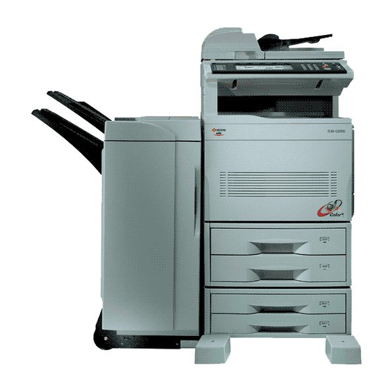
FINISHER INSTALLATION GUIDE
For installation on C830/C850 full-color copiers
MANUEL D'INSTALLATION DU FINISSEUR
Pour l'installation sur les copieurs entièrement en couleur C830/C850
GUÍA DE INSTALACIÓN DEL FINALIZADOR
Para instalar en las copiadoras C830/C850 a todo color
FINISHER-INSTALLATIONSANLEITUNG
Für die Installation an Vollfarben-Kopierern C830/C850
PROCEDURA DI INSTALLAZIONE DEL FINISHER
Per l'installazione su fotocopiatrici totalmente a colori C830/C850
フィニッシャ設置手順書
C830/C850フルカラー複写機に取り付ける場合
Publicidad
Tabla de contenido

Resumen de contenidos para Kyocera C830
- Página 1 FINISHER INSTALLATION GUIDE For installation on C830/C850 full-color copiers MANUEL D’INSTALLATION DU FINISSEUR Pour l'installation sur les copieurs entièrement en couleur C830/C850 GUÍA DE INSTALACIÓN DEL FINALIZADOR Para instalar en las copiadoras C830/C850 a todo color FINISHER-INSTALLATIONSANLEITUNG Für die Installation an Vollfarben-Kopierern C830/C850 PROCEDURA DI INSTALLAZIONE DEL FINISHER Per l’installazione su fotocopiatrici totalmente a colori C830/C850...
- Página 3 Supplied Parts H TP-A bronze screw (M4 × 10) ....2 Note: The two M4 × 14 TP-A chrome screws G I S-type tap-tight binding screw (M3 × 8) ..2 are not required for this installation. A Finisher ............1 J Fixing guide pin ..........
-
Página 4: Procédure D'iNstallation
Installation Guide • Dual 500-sheet Paper feed desk / duplex Pa- Turn off the copier’s main switch and unplug the per feed desk 2 copier’s power cord from the wall outlet before Finisher installation is possible only if the items •... - Página 5 1. Atlaching the Mount Assembly to 4. Hold the exit cover assembly M so that it is 3. Hold the FU tray 5 and FD cover 6 so that the Copier they are horizontal, and remove them from the horizontal, and attach it to the copier. copier.
-
Página 6: Montaje Del Finalizador
2. Mounting the Finisher 5. Lift the exit cover assembly M, turn the 7. Fasten the retainer B to the copier’s exit cover 0 using the 4 M4 × 8 TP-A chrome screws F. assembly’s two mount pieces 9 toward the 1. - Página 7 2. Unscrew the transport fastening screw D from 4. Remove the tape I securing the solenoid H, 3. Pull out the 2 fastening pins G holding the the rail unit A, move it into the front screw and the tape K securing the shifting guide collection tank F in place, and take the col- hole E, and screw it in.
- Página 8 6. Pull the rail unit A out of the finisher. 8. Move the finisher next to the copier, and open the finisher’s front cover. Adjust the height-adjust- 7. Loosely fasten the rail unit A to the copier’s ment screw N in the rail unit A until the guideline L marked on the retainer is aligned with the finisher-attachment area with the 2 M4 ×...
- Página 9 9. Pull the finisher away, and tighten up the 2 11. Open the finisher’s front cover P. 14. Remove the tape V securing the cushioning screws O to securely fasten the rail unit to 12. Remove the tape R securing the internal tray material U for the stapler unit T, and remove the copier’s finisher-attachment area.
- Página 10 19. Fasten the main tray D to the finisher using 15. Remove the 2 fastening pins W securing the 17. Lift the stapler unit T further up, and then the 2 fixing guide pins J and the 2 hexagonal stapler unit T at the bottom of the intermedi- lower it.
-
Página 11: Montaje Del Conjunto Eléctrico Opcional
20. Hold the auxiliary tray E vertically, attach it to 3. Mounting the Option Power As- 2. Remove 3 screws \ and take off the copier’s sembly the top of the finisher, and lower it toward the rear cover ]. exit side X. - Página 12 4. Fasten the option power assembly L to the 5. Connect the option power assembly’s 2-pin 6. Reattach the copier’s rear cover ] using the a and 6-pin b connectors, and reconnect the copier with the 2 M3 × 8 S-type tap-tight bind- 3 screws \ you removed at Step 2.
-
Página 13: Conexión Del Cable De Señal
4. Connecting the Signal Cable 7. Remove 2 screws d and take off the cover [C850 full-color machine with 100/120 V plate e on the rear cover. specifications only] 1. Connect the finisher’s signal cable f to the 8. Reconnect the connector [ to the rear of the Pass the finisher's signal cable f through the connector g on the copier. - Página 14 5. Checking and Adjusting 2. Check the centering of the punch-holes on the If holes are off-center toward the front of the test copy. copier (case [a] in illustration): 3. Loosen the 4 screws i securing the retainer • Move the retainer toward the rear of the machine (in [Adjust the punch-hole centering.] h, move the retainer as necessary to adjust the direction of the...
- Página 15 [Adjust the paper curl] If excessive downward curl (case [c] in illus- (3) Run paper through the machine. 1. Run paper through the machine. tration): (4) Check the downward curl on the ejected pa- 2. Check the curl on the paper ejected onto the (1) Open the finisher’s front cover P.
- Página 16 1 2 3 (2) Move the upper lever m one step to the right. (3) Run paper through the machine. If excessive upward curl (case [d] in illustra- Note: The lever is initially set to position “1,” and (4) Check the upward curl on the ejected paper. tion): can be adjusted to five positions (“1”...
- Página 17 MEMO...
- Página 18 MEMO...
- Página 19 MEMO...
- Página 20 2003. 6 3CH81013D...