Tabla de contenido
Publicidad
Idiomas disponibles
Idiomas disponibles
Enlaces rápidos
Harbor Breeze ® is a registered trademark of LF,
LLC. All Rights Reserved.
ATTACH YOUR RECEIPT HERE
Serial Number
Purchase Date
Questions, problems, missing parts? Before returning to your retailer, call our customer
service department at 1-800-643-0067, 8 a.m. - 6 p.m., EST, Monday - Thursday
8 a.m. - 5 p.m., EST Friday
PH18307
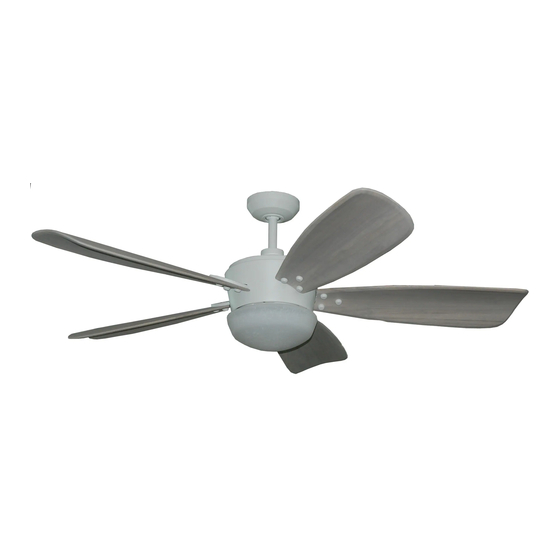
ITEM #1090752
SARATOGA II
CEILING FAN
MODEL #00581
UL MODEL #STG60
Español p. 16
1
Publicidad
Capítulos
Tabla de contenido
Solución de problemas

Manuales relacionados para Harbor Breeze SARATOGA II


Resumen de contenidos para Harbor Breeze SARATOGA II
- Página 1 ITEM #1090752 SARATOGA II CEILING FAN MODEL #00581 UL MODEL #STG60 Harbor Breeze ® is a registered trademark of LF, LLC. All Rights Reserved. Español p. 16 ATTACH YOUR RECEIPT HERE Serial Number Purchase Date Questions, problems, missing parts? Before returning to your retailer, call our customer service department at 1-800-643-0067, 8 a.m.
-
Página 2: Tabla De Contenido
TABLE OF CONTENTS WARNING • ELECTRIC SHOCK HAZARD - To reduce the risk of electric shock, do not use this fan with any Safety Information....................... 2 solid-state speed control device. Package Contents....................... 4 • ELECTRIC SHOCK HAZARD - To reduce the risk of electric shock, make sure electricity has been turned off at the circuit breaker or fuse box before beginning installation. -
Página 3: Package Contents
PACKAGE CONTENTS HARDWARE CONTENTS Wire Connector Blade Arm Screw Qty. 4 Qty. 16 Decorative Screw Blade Screw Qty. 15 Qty. 16 PART DESCRIPTION QUANTITY Mounting Bracket Canopy Canopy Cover PREPARATION Yoke Cover Before beginning assembly of product, make sure all parts are present. Compare parts with package 6 in. -
Página 4: Important
ASSEMBLY INSTRUCTIONS ASSEMBLY INSTRUCTIONS 1. Determine mounting method. 4a. STANDARD DOWNROD INSTALLATION: Downrod Mount (standard or angled ceiling) Insert downrod (E) through canopy (B), canopy cover (C), and yoke cover (D). Thread wires IMPORTANT: lf angle mounting, check to make sure from fan motor assembly through downrod (E). - Página 5 ASSEMBLY INSTRUCTIONS ASSEMBLY INSTRUCTIONS 6. Install hanger ball on top of downrod (E) into 9. Slide canopy (B) up against ceiling and over two mounting bracket (A) opening. Rotate fan until slot on screws on mounting bracket (A). Rotate canopy (B) hanger ball engages the tab on mounting bracket (A).
-
Página 6: Assembly Instructions
ASSEMBLY INSTRUCTIONS ASSEMBLY INSTRUCTIONS 12. Insert blade assembly through slot on fan motor 15. Place the fitter plate (I) over two screws and turn assembly (H) and align three screw holes in blade clockwise until it locks. Install previously removed arm (F) with screw holes in fan motor assembly (H). -
Página 7: Operating Instructions
ASSEMBLY INSTRUCTIONS OPERATING INSTRUCTIONS REMOTE CONTROL: 18. Align two key slots on light fitter assembly (J) with two screws on fitter plate (I). Place NOTE: If you have more than one remote-controlled fan installed in the same location, you may want to light fitter assembly (J) over two screws and change the frequency of the remote control to avoid any possible interference between remote controls. -
Página 8: Care And Maintenance
CARE AND MAINTENANCE WARRANTY The manufacturer warrants this fan to be free from defects in workmanship and material present at • To reduce the risk of fire, electric shock or injury to persons, care and maintain this fan. time of shipment from the factory for lifetime limited from the date of purchase. This warranty applies •... -
Página 9: Adjunte Su Recibo Aquí
ARTÍCULO # 1090752 VENTILADOR DE TECHO SARATOGA MODELO # 00581 MODELO UL # STG60 Harbor Breeze es una marca registrada de LF, LLC. ® Todos los derechos reservados. ADJUNTE SU RECIBO AQUÍ Número de serie Fecha de compra ¿Preguntas, problemas, piezas faltantes? Antes de volver a la tienda, llame a nuestro Departamento de Servicio al Cliente al 1-800-643-0067, de lunes a jueves, de 8 a. -
Página 10: Información De Seguridad
ÍNDICE ADVERTENCIA • PELIGRO DE DESCARGA ELÉCTRICA: Para reducir el riesgo de descargas eléctricas, Información de seguridad......................17 no use este ventilador con dispositivos de control de velocidad de estado sólido. Contenido del paquete......................19 • RIESGO DE DESCARGA ELÉCTRICA: Para reducir el riesgo de descargas eléctricas, asegúrese de cortar la electricidad en la caja del interruptor de circuito o en la caja de fusibles Aditamentos.......................20 antes de comenzar la instalación. -
Página 11: Contenido Del Paquete
CONTENIDO DEL PAQUETE ADITAMENTOS Tornillo para el Conector brazo de las aspas de cables Cant. 16 Cant. 4 Tornillo decorativo Tornillo para aspas Cant. 15 Cant. 16 PIEZA DESCRIPCIÓN CANTIDAD Soporte de montaje Base Cubierta de la base PREPARACIÓN Cubierta de la horquilla Antes de comenzar a ensamblar el producto, asegúrese de tener todas las piezas. -
Página 12: Instrucciones De Ensamblaje
INSTRUCCIONES DE ENSAMBLAJE INSTRUCCIONES DE ENSAMBLAJE 1. Determine el método de instalación. 4a. INSTALACIÓN ESTÁNDAR CON VARILLA: Montaje de varilla (techos estándar o en ángulo) Inserte la varilla (E) por la base (B), la cubierta de la base (C) y la cubierta de la horquilla (D). IMPORTANTE: Si realiza la instalación en ángulo, Pase los cables desde el ensamble del motor verifique que el ángulo del techo no tenga una... - Página 13 INSTRUCCIONES DE ENSAMBLAJE INSTRUCCIONES DE ENSAMBLAJE 6. Instale la bola para colgar en la parte superior de la 9. Deslice la base (B) contra el techo y por los varilla (E) en la abertura del soporte de montaje (A). dos tornillos en el soporte de montaje (A). Gire el ventilador hasta que la ranura de la bola para Gire la base (B) en dirección de las manecillas colgar calce con la lengüeta del soporte de montaje (A).
- Página 14 INSTRUCCIONES DE ENSAMBLAJE INSTRUCCIONES DE ENSAMBLAJE 12. Inserte el ensamble del aspa a través de la ranura 15. Coloque la placa de soporte (I) sobre los dos en el ensamble del motor del ventilador (H) y alinee tornillos y gírela en dirección de las manecillas los tres orificios para tornillos en el brazo del aspa (F) Ranura del reloj hasta que se bloquee.
-
Página 15: Instrucciones De Funcionamiento
INSTRUCCIONES DE ENSAMBLAJE INSTRUCCIONES DE FUNCIONAMIENTO CONTROL REMOTO: 18. Alinee los dos chaveteros del ensamble del soporte de iluminación (J) con los dos tornillos en la placa NOTA: Si tiene más de un ventilador a control remoto instalado en la misma ubicación, se recomienda cambiar de soporte (I). -
Página 16: Cuidado Y Mantenimiento
CUIDADO Y MANTENIMIENTO GARANTÍA El fabricante garantiza que este ventilador no presenta defectos de fabricación ni en los materiales • Para reducir el riesgo de incendios, descargas eléctricas o lesiones personales, trate este presentes en el momento del transporte desde la fábrica, durante un período limitado de por vida ventilador con cuidado y realice el mantenimiento correspondiente.