Tabla de contenido
Publicidad
Idiomas disponibles
Idiomas disponibles
Enlaces rápidos
ATTACH YOUR RECEIPT HERE
Purchase Date
Questions, problems, missing parts? Before returning to your retailer, call our customer
service department at 1-800-527-1292, 8:30 a.m. - 5 p.m., CST, Monday - Friday.
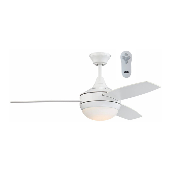
BEACH CREEK
LED CEILING FAN
1
ITEM #1145471
0923049
MODEL #TG44LW3D1RS
TG44OSB3D1RC
Español p. 21
Publicidad
Capítulos
Tabla de contenido
Solución de problemas

Manuales relacionados para Harbor Breeze TG44LW3D1RS


Resumen de contenidos para Harbor Breeze TG44LW3D1RS
- Página 1 ITEM #1145471 0923049 BEACH CREEK LED CEILING FAN MODEL #TG44LW3D1RS TG44OSB3D1RC Español p. 21 ATTACH YOUR RECEIPT HERE Purchase Date Questions, problems, missing parts? Before returning to your retailer, call our customer service department at 1-800-527-1292, 8:30 a.m. - 5 p.m., CST, Monday - Friday.
-
Página 2: Tabla De Contenido
TABLE OF CONTENTS Safety Information ......................... 3 Package Contents ........................ 5 Hardware Contents ........................... 6 Preparation ........................... 6 Initial Installation ........................6 Downrod-Style Fan Mounting ....................9 Closemount-Style Fan Mounting ..................11 Wiring ...........................13 Final Installation ........................15 Operating Instructions ......................16 Care and Maintenance ...................... -
Página 3: Safety Information
SAFETY INFORMATION Modifications not approved by the party responsible for compliance could void the user's authority to operate the equipment. *NOTE: This equipment has been tested and found to comply with the limits for a Class B digital device, pursuant to Part 15 of the FCC Rules. These limits are designed to provide reasonable protection against harmful interference in a residential installation. - Página 4 SAFETY INFORMATION WARNING WARNING To reduce the risk of fire, electrical shock or personal injury, mount fan to outlet box marked "ACCEPTABLE FOR FAN SUPPORT OF 35 LBS. OR LESS" and use mounting screws provided with the outlet box. Most outlet boxes commonly used for the support of lighting fixtures are not acceptable for fan support and may need to be replaced.
-
Página 5: Package Contents
PACKAGE CONTENTS PART DESCRIPTION QUANTITY PART DESCRIPTION QUANTITY Downrod Glass Shade Canopy Pin (preassembled) Mounting Bracket Clip (preassembled) Motor Housing Remote Control Receiver Yoke Cover Remote Pack LED Light Kit (preassembled) Canopy Mounting Screw (preassembled) Motor Screw (preassembled) Lock Washer (preassembled) Blade IMPORTANT REMINDER: You must use the parts provided with this fan for proper installation... -
Página 6: Hardware Contents
HARDWARE CONTENTS (shown actual size) Fiber Blade Blade Screw Wire Washer Connector Qty. 9 Qty. 9 + 1 extra Qty. 4 + 1 extra PREPARATION Before beginning assembly of product, make sure all parts are present. Place motor on carpet or on foam to avoid damage to finish. - Página 7 INITIAL INSTALLATION 2. Determine mounting method to use. A. Downrod mount (standard or angled ceiling) 19° max. B. Closemount (standard ceiling only) IMPORTANT: If using the angle mount, check to make sure the ceiling angle is not steeper than 19°. *Helpful Hint: Downrod-style mounting is best suited for ceilings 8 ft.
- Página 8 INITIAL INSTALLATION 5. Remove 6 motor screws (H) and 6 lock washers (I) from top of motor housing (D). Remove the yoke plate and top plate from motor housing (D). yoke plate top plate Slide one blade (J) through one of the rectangular openings on center band of motor housing (D).
-
Página 9: Important
INITIAL INSTALLATION Secure mounting bracket (C) to outlet box (not included) using screws, spring washers and flat ANGLE STANDARD washers provided with the outlet box. MOUNT MOUNT *NOTE: It is very important you use the proper hardware when installing the mounting bracket (C) as this will support the fan. - Página 10 DOWNROD-STYLE FAN MOUNTING Insert downrod (A) through canopy (B), and yoke cover (E). Thread wires from motor housing (D) up through downrod (A). Slip downrod (A) into yoke, align holes and re-install pin (L) and clip (M). Tighten set screws and then tighten nuts.
-
Página 11: Closemount-Style Fan Mounting
DOWNROD-STYLE FAN MOUNTING If you cut back the lead wires in Step 4, strip 1/2 in. of insulation from end of each wire -- WHITE, BLACK, GREEN and BLUE. Twist stripped ends of each strand of wire within the insulation with pliers (not included). - Página 12 CLOSEMOUNT-STYLE FAN MOUNTING Remove every other motor screw (H) and lock washer (I) from top of motor housing (D). Pull wires up through hole in the middle of the canopy (B). Align larger holes in canopy (B) with 3 screws in top of motor housing (D). Attach canopy (B) to motor housing (D) using the three motor screws (H) and lock washers (I) previously removed.
-
Página 13: Wiring
WIRING WARNING: To reduce the risk of fire, electrical shock or personal injury, wire connectors provided with this fan are designed to accept only one 12-gauge house wire and two lead wires from the fan. If your house wire is larger than 12-gauge or there is more than one house wire to connect to the corresponding fan lead wires, consult an electrician for the proper size wire connectors to use. - Página 14 WIRING Wrap electrical tape (not included) around each individual wire connector (CC) down to the wire. WARNING: Make sure no bare wire or wire strands are visible after making connections. Place GREEN and WHITE connections on opposite side of the outlet box from the BLACK and BLUE (if applicable) connections.
-
Página 15: Final Installation
FINAL INSTALLATION 1. Lift canopy (B) to mounting bracket (C) again, aligning slotted holes in canopy (B) with loosened canopy mounting screws (G) in mounting bracket Closemount Downrod (C). Twist canopy (B) clockwise to lock. Re-insert Option Option the two canopy mounting screws (G) previously removed (Step 4, page 7) and tighten all canopy mounting screws (G) securely. -
Página 16: Operating Instructions
OPERATING INSTRUCTIONS CAUTION: The remote control transmitter can be programmed to multiple receivers or fans. If this is not desired, turn wall switch off to any other programmable receiver or fan. FCC Compliance Notice for Remote Control Modifications not approved by the party responsible for compliance could void the user's authority to operate the equipment. - Página 17 OPERATING INSTRUCTIONS 2. Restore electrical power. Within 30 seconds of restoring electrical power, press and hold the “0” button on the remote control transmitter for 5 seconds or until light on the fan blinks twice. Use the remote control transmitter to test the light and fan functions to confirm the learning process is complete.
-
Página 18: Care And Maintenance
OPERATING INSTRUCTIONS 4a. In warmer weather, setting the reverse switch in the LEFT position will result in downward airflow creating a wind chill effect. 4b. In cooler weather, setting the reverse switch in the RIGHT position will result in upward airflow that can help move stagnant, hot air off the ceiling area. -
Página 19: Troubleshooting
TROUBLESHOOTING WARNING: Before beginning work, shut off the power supply to avoid electrical shock. PROBLEM POSSIBLE CAUSE CORRECTIVE ACTION Fan does not move. 1. Reverse switch not engaged. 1. Push switch firmly either left or right. 2. Power is off or fuse is blown. 2. -
Página 20: Limited Lifetime Warranty
LIMITED LIFETIME WARRANTY The distributor warrants this fan to be free from defects in workmanship and materials present at time of shipment from the factory for Lifetime limited from the date of purchase. This warranty applies only to the original purchaser. The distributor agrees to correct any defect at no charge or, at our option, replace the ceiling fan with a comparable or superior model. -
Página 21: Adjunte Su Recibo Aquí
ARTÍCULO # 1145471 0923049 VENTILADOR DE TECHO LED BEACH CREEK MODELO # TG44LW3D1RS TG44OSB3D1RC ADJUNTE SU RECIBO AQUÍ Fecha de compra ¿Preguntas, problemas, piezas faltantes? Antes de volver a la tienda, llame a nuestro Departamento de Servicio al Cliente al 1-800-527-1292, de lunes a viernes de 8:30 a.m. a 5 p.m. - Página 22 ÍNDICE Información de seguridad .....................23 Contenido del paquete ......................25 Aditamentos ..........................26 Preparación .......................... 26 Instalación inicial ........................26 Montaje del ventilador en estilo de varilla ................29 Montaje del ventilador en estilo cerrado ................31 Cableado ..........................33 Instalación final ........................35 Instrucciones de funcionamiento ..................
-
Página 23: Información De Seguridad
INFORMACIÓN DE SEGURIDAD Las modificaciones que no estén aprobadas por la parte responsable del cumplimiento podrían anular la autorización del usuario para utilizar el equipo. *NOTA: este equipo ha sido probado y se ha verificado que cumple con los límites para un dispositivo digital clase B, conforme a la sección 15 de las reglas de la FCC. - Página 24 INFORMACIÓN DE SEGURIDAD ADVERTENCIA ADVERTENCIA Para reducir el riesgo de incendio, descargas eléctricas o lesiones personales, monte el ventilador en una caja de salida marcada como "ACCEPTABLE FOR FAN SUPPORT OF 35 LBS. OR LESS" (APTA PARA SOSTENER VENTILADORES DE 15,87 KG O MENOS) y utilice los tornillos de montaje que se proporcionan con la caja de salida.
-
Página 25: Contenido Del Paquete
CONTENIDO DEL PAQUETE PIEZA DESCRIPCIÓN CANTIDAD PIEZA DESCRIPCIÓN CANTIDAD Varilla Pantalla de vidrio Base Pasador (preensamblado) Soporte de montaje Sujetador (preensamblado) Carcasa del motor Receptor del control remoto Cubierta de la horquilla Paquete remoto Kit de iluminación LED (preensamblado) Tornillo de montaje de la base (preensamblado) Tornillo del motor (preensamblado) -
Página 26: Aditamentos
ADITAMENTOS (se muestran en tamaño real) Tornillo Arandela para para aspa aspa de fibra Conector de cables Cant.: 9 Cant.: 9 + 1 adicional + 1 adicional Cant.: 4 PREPARACIÓN Antes de comenzar a ensamblar el producto, asegúrese de tener todas las piezas. Ubique el motor sobre una alfombra o espuma para evitar dañar el acabado. -
Página 27: Importante
INSTALACIÓN INICIAL 2. Determine el método de instalación que utilizará. A. Montaje de varilla (techo estándar o en ángulo) 19° máx. B. Montaje cerrado (solo para techos estándar) IMPORTANTE: Si realiza la instalación en ángulo, verifique que el ángulo del techo no tenga una inclinación superior a los 19°. -
Página 28: Aditamentos Utilizados
INSTALACIÓN INICIAL 5. Retire 6 tornillos del motor (H) y 6 arandelas de seguridad (I) de la parte superior de la carcasa del motor (D). Retire la placa de la horquilla y la placa placa de la superior de la carcasa del motor (D). horquilla placa superior... -
Página 29: Montaje Del Ventilador En Estilo De Varilla
INSTALACIÓN INICIAL Asegure el soporte de montaje (C) a la caja de salida (no se incluye) con los tornillos, las MONTAJE MONTAJE arandelas de resorte y las arandelas planas EN ÁNGULO ESTÁNDAR que incluye la caja de salida. *NOTA: Es muy importante que use los aditamentos adecuados para instalar el soporte de montaje (C), ya que este soportará... - Página 30 MONTAJE DEL VENTILADOR EN ESTILO DE VARILLA Introduzca la varilla (A) a través de la base (B) y la cubierta de la horquilla (E). Pase los conductores desde la carcasa del motor (D) a través de la varilla (A). Deslice la varilla (A) en la horquilla, alinee los orificios y vuelva a instalar el pasador (L) y el sujetador (M).
-
Página 31: Montaje Del Ventilador En Estilo Cerrado
MONTAJE DEL VENTILADOR EN ESTILO DE VARILLA Si decidió cortar los cables conductores en el paso 4, pele 1,27 cm del aislamiento del extremo de cada cable: BLANCO, NEGRO, VERDE Y AZUL. Tuerza los extremos pelados de cada filamento de cable dentro del aislamiento con pinzas (no se incluyen). - Página 32 MONTAJE DEL VENTILADOR EN ESTILO CERRADO Retire cada otro tornillo del motor (H) y la arandela de seguridad (I) de la parte superior de la carcasa del motor (D). Pase los cables hacia arriba a través del orificio en el centro de la base (B). Alinee los orificios grandes de la base (B) con los 3 tornillos en la parte superior de la carcasa del motor (D).
-
Página 33: Cableado
CABLEADO ADVERTENCIA: Para reducir el riesgo de incendios, descargas eléctricas o lesiones personales, los conectores de cables incluidos con este ventilador están diseñados para soportar solo un cable de la casa de calibre 12 y dos cables conductores del ventilador. Si el cable de la casa es de un calibre superior a 12 o hay más de un cable para conectar a los cables conductores del ventilador correspondientes, consulte a un electricista cuál es el tamaño adecuado de los conectores de cables que debe utilizar. - Página 34 CABLEADO Cubra con cinta aislante (no se incluye) cada conector de cables (CC) individual hacia abajo del cable. ADVERTENCIA: Asegúrese de que no haya conductores desnudos ni filamentos de cables visibles después de hacer las conexiones. Coloque los cables VERDE y BLANCO en el lado opuesto de la caja de salida con respecto a las conexiones de los cables NEGRO y AZUL.
-
Página 35: Instalación Final
INSTALACIÓN FINAL 1. Levante la base (B) hacia el soporte de montaje (C) nuevamente, alineando los orificios ranurados en la Opción de montaje base (B) con los tornillos de montaje de la base (G) Opción de varilla cerrado aflojados del soporte de montaje (C). Gire la base (B) en dirección de las manecillas del reloj para asegurar. -
Página 36: Instrucciones De Funcionamiento
INSTRUCCIONES DE FUNCIONAMIENTO PRECAUCIÓN: El transmisor para control remoto se puede programar para varios receptores o ventiladores. Si usted no desea hacer esto, desactive el interruptor de pared para cualquier otro receptor o ventilador programable. Aviso de cumplimiento de la FCC para el control remoto Las modificaciones que no estén aprobadas por la parte responsable del cumplimiento podrían anular la autorización del usuario para utilizar el equipo. - Página 37 INSTRUCCIONES DE FUNCIONAMIENTO 2. Restablezca la alimentación eléctrica. Antes de que transcurran 30 segundos de haber restablecido la alimentación eléctrica, mantenga presionado el botón "0" (apagado) en el control remoto durante 5 segundos o hasta que la luz del ventilador titile dos veces. Use el trasmisor para control remoto a fin de probar las funciones de la luz y del ventilador, y así...
-
Página 38: Cuidado Y Mantenimiento
INSTRUCCIONES DE FUNCIONAMIENTO 4a. En climas más cálidos la configuración del interruptor de reversa en la posición a la IZQUIERDA creará un flujo de aire descendente que generará un efecto de viento refrescante. 3b. En climas más fríos la configuración del interruptor de reversa en la posición a la DERECHA creará... -
Página 39: Solución De Problemas
SOLUCIÓN DE PROBLEMAS ADVERTENCIA: Antes de comenzar cualquier trabajo, desconecte el suministro de electricidad para evitar descargas eléctricas. PROBLEMA CAUSA POSIBLE ACCIÓN CORRECTIVA El ventilador no 1. El interruptor de reversa no está 1. Mueva firmemente el interruptor se mueve. activado. -
Página 40: Garantía Limitada De Por Vida
GARANTÍA LIMITADA DE POR VIDA El distribuidor garantiza que este ventilador no presenta defectos en la mano de obra ni en los materiales presentes al momento del transporte desde la fábrica durante un período limitado de por vida a partir de la fecha de compra. Esta garantía es válida solo para el comprador original. El distribuidor acepta reparar cualquier defecto sin cargo o, según nuestro criterio, remplazar el ventilador de techo por un modelo comparable o superior.