Registrarse
Cargar
Manuales
Marcas
Castolin Eutectic Manuales
Sistemas de Soldadura
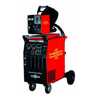
TotalArc 5000
Castolin Eutectic TotalArc 5000 Manuales
Manuales y guías de usuario para Castolin Eutectic TotalArc 5000. Tenemos
1
Castolin Eutectic TotalArc 5000 manual disponible para descarga gratuita en PDF: Manual De Instrucciones
Castolin Eutectic TotalArc 5000 Manual De Instrucciones (161 páginas)
Marca:
Castolin Eutectic
| Categoría:
Sistemas de Soldadura
| Tamaño: 8.94 MB
Tabla de contenido
Deutsch
2
Tabla de Contenido
2
Sehr Geehrter Castolin-Kunde
2
Sicherheitsvorschriften
3
Allgemeines
3
Bestimmungsgemässe Verwendung
3
Verpflichtungen des Betreibers
3
Verpflichtungen des Personals
3
Persönliche Schutzausrüstung
3
Gefahr durch Schädliche Gase und Dämpfe
3
Gefahr durch Funkenflug
3
Gefahren durch Netz- und Schweiss-Strom
3
Besondere Gefahrenstellen
3
Informelle Sicherheitsmassnahmen
4
Sicherheitsmassnahmen am Aufstellort
4
Vagabundierende Schweisströme
4
Sicherheitsmassnahmen IM Normalbetrieb
4
Sicherheitstechnische Inspektion
4
Veränderungen am Schweissgerät
4
Ersatz- und Verschleissteile
4
Kalibrieren von Schweissgeräten
4
Die CE-Kennzeichnung
4
Urheberrecht
4
Allgemeines
5
Prinzip der Totalarc 2 3000 / 4000 / 5000
5
Gerätekonzept
5
Einsatzgebiete
5
Beschreibung des Bedienpanels
6
Bedienelemente und Anschlüsse
8
Stromquelle Totalarc² 3000
8
Stromquelle Totalarc² 4000 / 5000
9
Drahtvorschub DS III
10
Fernbedienung RC 2
11
Fernbedienung RC 4
11
4 Takt Betrieb
12
2 Takt Betrieb
12
4 Takt Betrieb Aluminium
12
Schweißbrenner-Betriebsarten
12
Punktieren
13
Schweißgerät in Betrieb Nehmen
14
Bestimmungsgemäße Verwendung
14
Aufstellbestimmungen
14
Netzanschluß
14
Option Drahtvorschubaufnahme Montieren
14
Verbindungsschlauchpaket an Stromquelle Anschliessen
14
Verbindungsschlauchpaket an Drahtvorschub Anschliessen
15
Gasflasche Montieren / Anschliessen
15
Schweißbrenner Montieren
15
Kühlgerät in Betrieb Nehmen
15
Schutzgasmenge Einstellen
16
Drahtspule Einsetzen
16
Drahtelektrode Einlaufen Lassen
16
Vorschubrollen Wechseln
16
Anschliessen
15
MIG/MAG-Schweißen
17
Manuell
17
Funktion Ignition Time-Out
17
Sonder-2-Takt Betrieb für Automateninterface
17
E-Handschweißen
18
WIG-Schweißen
18
Job-Betrieb
19
Job Erstellen
19
Job Kopieren / Überschreiben
19
Job Löschen
20
Job Abrufen
20
Das Setup-Menü
21
In das Setup-Menü Einsteigen
21
Parameter Ändern
21
Das Setup-Menü Verlassen
21
Parameter Verfahren „MIG/MAG Standard- / Impulslichtbogen Schweißen
21
Parameter Verfahren „WIG-Schweißen
21
Parameter Verfahren „E-Handschweißen
21
Parameter Betriebsart „2-Takt Betrieb für Automateninterface
22
Parameter Betriebsart „4-Takt Betrieb Aluminium
22
Parameter Betriebsart „Punktieren
22
2Nd - Zweite Ebene des Setup-Menüs
22
Pushpull-Unit
23
Fehlermeldungen an den Anzeigen
23
Fehlerdiagnose und -Behebung
24
Fehlermeldungen an den Anzeigen
24
Stromquelle Totalarc 2 3000 / 4000 / 5000
25
Pflege und Wartung
26
Technische Daten
27
Stromquelle Totalarc² 3000 / 4000 / 5000
27
Kühlgerät (Eingebaut in Stromquelle)
27
Drahtvorschub DS III
27
English
30
Dear Castolin Customer
30
Safety Rules
31
General Remarks
31
Utilisation for Intended Purpose Only
31
Obligations of Owner/Operator
31
Obligations of Personnel
31
Personal Protective Equipment
31
Hazards from Noxious Gases and Vapours
31
Hazards from Flying Sparks
31
Hazards from Mains and Welding Current
31
Particular Danger Spots
31
Safety Precautions at the Installation Location
32
Vagrant Welding Currents
32
Safety Precautions in Normal Operation
32
Safety Inspection
32
Alterations to the Welding Machine
32
Spares and Wearing Parts
32
Calibration of Welding Machines
32
CE-Marking
32
Copyright
32
General Remarks
33
Principle of the Digital Family of Machines
33
Machine Concept
33
Areas of Use
33
Description of Control Panel
34
Controls and Connections
36
Power Source Totalarc² 3000
36
Power Source Totalarc² 4000 / 5000
37
DS III Wire Feeder
38
RC 2 Remote-Control Unit
39
RC 4 Remote-Control Unit
39
2 Step Mode
40
Torch Operating Modes
40
4-Step Mode
40
4-Step Mode (Aluminium)
40
Spot Welding
41
Starting to Use the Welding Machine
42
Utilisation for Intended Purpose Only
42
Machine Set-Up Regulations
42
Mains Connection
42
Mounting the Optional Wirefeeder Fixture
42
Fixing the Interconnecting Cable to the Power Source
42
Connecting the Interconnecting Cable to the Wirefeeder
43
Mounting / Connecting the Gas Cylinder
43
Installing the Welding Torch
43
Starting up the Cooling Unit
43
Setting the Shielding-Gas Rate
44
Mounting the Wire Spool
44
Feeding in the Wire Electrode
44
Changing the Feed Rollers
44
To the Power Source
43
MIG/MAG Welding
45
Manual
46
Ignition Time-Out Function
46
Special 2-Step Mode for Automatic Interface
46
Manual Electrode Welding
47
TIG Welding
47
Job Mode
48
Creating a Job
48
Copy / Overwrite Job
48
Deleting a Job
49
Retrieving a Job
49
The Set-Up Menu
50
Accessing the Setup-Menu
50
Changing the Parameter
50
Exit the Set-Up Menu
50
Parameters for "MIG/MAG Standard / Pulsed-Arc Welding" Process
50
Parameters for "TIG Welding
50
Parameters for "Manual Electrode Welding" Process
50
Special 2-Step Mode for Robot Interface
51
Parameters for "Aluminium 4-Step" Mode
51
Parameters for "Spot Welding" Mode
51
2Nd - Second Level of Set-Up Menu
51
Pushpull Unit
52
Error Codes on the Display
52
Troubleshooting
53
Error Messages on the Displays
53
Totalarc² 3000 / 4000 / 5000 Power Source
54
Care and Maintenance
55
Technical Data
56
Total Arc² 3000 / 4000 / 5000 Power Source
56
Cooling Unit (Built in Power Source)
56
DS III Wire Feeder
56
Italiano
86
Egregio Cliente Della Castolin
86
Della Saldatura
87
Norme DI Sicurezza
87
In Generale
87
Uso in Conformità alle Istruzioni
87
Responsabilità Dell'esercente
87
Responsabilità del Personale
87
Equipaggiamento DI Protezione Personale
87
Pericoli Attraverso Gas E Vapori Nocivi
87
Pericoli Attraverso Scintillamento
87
Pericolo Attraverso Corrente Della Rete E Della Saldatura
87
Punti Particolarmente Pericolosi
87
Misure DI Sicurezza Informali
88
Misure DI Sicurezza Sul Luogo DI Installazione
88
Correnti Vaganti
88
Misure DI Sicurezza Nell`esercizio Normale
88
Ispezione DI Sicurezza Tecnica
88
Modifiche Alla Saldatrice
88
Parti DI Ricambio E D`usura
88
Calibratura DI Saldatrici
88
Il Contrassegno CE
88
Diritti D'autore
88
Informazioni Generali
89
Principio del Totalarc² 3000 / 4000 / 5000
89
Concezione Dell'apparecchio
89
Settori D'applicazione
89
Descrizione del Pannello DI Comando
90
Comandi E Attacchi
92
Fonte Elettrica Totalarc² 3000
92
Fonte Elettrica Totalarc² 4000 / 5000
93
Alimentatori Filo DS III
94
Telecomando RC 2
95
Telecomando RC 4
95
Modi DI Funzionamento del Cannello Della Saldatrice
96
Funzionamento a Due Tempi
96
Funzionamento a 4 Tempi
96
Funzionamento a 4 Tempi Alluminio
96
Saldatura a Punti
97
Messa in Funzione Della Saldatrice
98
Utilizzo Appropriato
98
Istruzioni Per L'installazione
98
Collegamento Alla Rete
98
Montaggio Opzione Porta Avanzamento Filo
98
Allacciamento del Pacco Tubo Collegamento Alla Fonte DI Corrente
98
Allacciamento del Pacco Tubo Collegamento All'alimentazione Filo
99
Come Montare / Collegare la Bombola del Gas
99
Montaggio del Cannello DI Saldatura
99
Messa in Funzione del Raffreddatore
99
Regolazione Della Quantità DI Gas Inerte
100
Applicare la Bobina del Filo
100
Come Inserire Il Filo Dell'elettrodo
100
Sostituzione Dei Rulli D'avanzamento
100
Alla Fonte DI Corrente
99
Saldatura MIG/MAG
101
Funzionamento Manuale
102
Funzione Ignition Time-Out
102
Funzionamento Speciale a Due Fasi Per
102
Interfaccia con Il Robot
102
Saldatura Manuale E
103
Saldatura WIG
103
Funzione Lavorazione
104
Esecuzione Della Lavorazione
104
Come Copiare /Sovrascrivere una Lavorazione
104
Come Cancellare una Lavorazione
105
Come Richiamare una Lavorazione
105
Il Menù DI Settaggio
106
Come Entrare Nel Menù DI Settaggio
106
Come Modificare I Parametri
106
Come Uscire Dal Menù DI Settaggio
106
Parametro Sistema „Saldatura con Arco Voltaico Ad Impulsi Standard MIG/MAG
106
Parametro Funzione „Saldatura WIG
106
Parametro Funzione „Saldatura Manuale E
106
Funzionamento Speciale a Due Fasi Per Interfaccia con Il Robot
107
Parametro Funzione „Lavorazione a 4 Tempi in Alluminio
107
Parametro Funzione „Lavorazione a Punti
107
2Nd - Secondo Livello del Menù DI Settaggio
107
Unità Pushpull
108
Identificazione E Risoluzione Dei Problemi
109
Spie DI Segnalazione Dei Problemi
109
Fonte Elettrica Totalarc² 3000 / 4000 / 5000
110
Cura E Manutenzione
111
Dati Tecnici
112
Fonte Elettrica Totalarc² 3000 / 4000 / 5000
112
Refrigeratore (Incorporato Nella Fonte DI Corrente)
112
Alimentatore Filo DS III
112
Español
114
Distinguido Cliente de Castolin
114
Soldadura
115
Normas de Seguridad
115
Generalidades
115
Uso Previsto
115
Obligaciones del Propietario
115
Obligaciones del Personal
115
Equipo de Protección Personal
115
Peligro por Gases y Vapores Nocivos
115
Peligro por Chispas Voladoras
115
Peligro por la Corriente Eléctrica y la Corriente de Soldadura
115
Focos Principales de Peligro
115
Medidas de Seguridad Informales
116
Medidas de Seguridad en el Lugar de Emplazamiento
116
Corrientes de Soldadura Vagabundas
116
Medidas de Seguridad en Funcionamiento Normal
116
Inspección Técnica
116
Cambios en la Soldadora
116
Piezas de Repuesto y de Desgaste
116
Calibrado de Soldadoras
116
El Distintivo CE
116
Derechos de Propiedad
116
Generalidades
117
Principio del Totalarc 2 3000 / 4000 / 5000
117
Concepto del Aparato
117
Campos de Aplicación
117
Descripción del Panel de Control
118
Elementos de Manejo y Conexiones
120
Fuente de Corriente Totalarc² 3000
120
Fuente de Corriente Totalarc² 4000 / 5000
121
Devanadera de Alambre DS III
122
Mando a Distancia RC 2
123
Mando a Distancia RC 4
123
Modos de Operación del Soplete
124
Operación 2 Pasos
124
Modo de 4 Pasos
124
Operación 4 Pasos Aluminio
124
Soldadura por Puntos
125
De Alambre
126
Puesta en Marcha de la Máquina de Soldar
126
Utilización Prevista
126
Directrices de Emplazamiento
126
Conexión a la Red
126
Opción de Montaje de Alojamiento de Avance de Alambre
126
Conectar el Paquete de Mangueras de Conexión a la Fuente de Corriente
126
Conectar el Paquete de Mangueras de Conexión al Avance de Alambre
127
Montar y Conectar la Bombona de Gas
127
Montaje del Soplete de Soldar
127
Puesta en Marcha de Aparato Refrigerador
127
Ajuste de la Cantidad de Gas Protector
128
Colocar la Bobina de Alambre
128
Introducción del Electrodo de Alambre
128
Cambiar Los Rodillos de Transporte
128
A la Fuente de Corriente
127
Soldadura MIG/MAG
129
Manual
130
Función Ignition Time-Out
130
Operación Especial 2 Tiempos para Interfaz de Robot
130
Soldadura Manual E
131
Soldadura WIG
131
Operación con Tareas
132
Crear Tarea
132
Copiar / Sobrescribir Tarea
132
Borrar una Tarea
133
Abrir una Tarea
133
El Menú Setup
134
Para Pasar al Menú Setup
134
Modificar Parámetros
134
Salir del Menú Setup
134
Parámetros del Procedimiento "Soldadura MIG/MAG Estándar / Impulso de Arco de Luz
134
Parámetros del Procedimiento "Soldadura WIG
134
Parámetros del Procedimiento "Soldadura Manual E
134
Operación Especial de 2 Tiempos para Interfaz de Robot
135
Parámetros del Modo de Operación "Operación 4 Pasos Aluminio
135
Parámetros de Modo de Operación "Soldadura por Puntos
135
2Nd - Segundo Nivel del Menú Setup
135
Unidad Pushpull
136
Diagnóstico y Solución de Errores
137
Mensajes de Error en Los Indicadores
137
Cuidado y Mantenimiento
139
Fuente de Corriente Totalarc² 3000 / 4000 / 5000
140
Datos Técnicos
140
Aparato Refrigerador (Incorporado en la Fuente de Corriente)
140
Devanador de Alambre DS III
140
Lista de Repuestos
141
Publicidad
Publicidad
Productos relacionados
Castolin Eutectic TotalArc 3000
Castolin Eutectic TotalArc 4000
Castolin Eutectic AutoMax 600
Castolin Eutectic Casto TIG 2.5 FP Pulse
Castolin Eutectic Derby 202
Castolin Eutectic DPT 400i
Castolin Eutectic GS 850
Castolin Eutectic GSi 600
Castolin Eutectic GSX 750 HD
Castolin Eutectic MIG PULSE 3003 DP
Castolin Eutectic Categorias
Sistemas de Soldadura
Herramientas Eléctricas
Pistolas de Soldar
Equipo Industrial
Inversores
Más Castolin Eutectic manuales
Login
Entrar
O
Iniciar sesión con Facebook
Iniciar sesión con Google
Cargar el manual
Cargar desde el disco
Cargar desde la URL