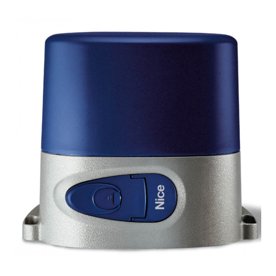
Nice ROBO RO 300 Manual De Instrucciones
Motorreductor electromecánico para cancelas correderas
Ocultar thumbs
Ver también para ROBO RO 300:
- Manual de instrucciones (100 páginas) ,
- Manual de instrucciones y catálogo de recambios (12 páginas)
Tabla de contenido
Publicidad
Idiomas disponibles
Idiomas disponibles
R O B O
I
MANUALE
ISTRU ZIO NI
E CATALOGO
RICAMBI
Motoriduttore
elettromeccanico
per cancelli
scorrevoli
QUESTO LIBRETTO È DESTINATO SOLO ALL'INSTALLATORE.
L'installazione dovrà essere effettuata solamente da per so na le professionalmente qualifi cato in conformità a quanto previsto
dalla legge n° 46 del 5 marzo 1990 e successive mo di fi che ed integrazioni e nel pieno rispetto delle norme UNI 8612.
GB
INSTRUCTIONS
LIVRET
MANUAL
D'INSTRUCTIONS
AND SPARE
ET CATALOGUE
PARTS
DES
CATALOGUE
RECHANGES
Electromechanical
Mototréducteur
gearmotor for
électromécanique
sliding gates
pour portails
coulissants
F
D
ANLEITUNGSHEFT
UND
ERSATZTEIL-
KATALOG
Elektromechanischer
Antrieb für
Gleittore
V. 010
E
MANUAL DE
INSTRUCCIONES
Y CATÁLOGO
DE RECAMBIOS
Motorreductor
electromecánico
para cancelas
correderas
Publicidad
Capítulos
Tabla de contenido

Manuales relacionados para Nice ROBO RO 300


Resumen de contenidos para Nice ROBO RO 300
- Página 1 V. 010 R O B O INSTRUCTIONS LIVRET MANUALE ANLEITUNGSHEFT MANUAL DE MANUAL D’INSTRUCTIONS ISTRU ZIO NI INSTRUCCIONES AND SPARE ET CATALOGUE E CATALOGO ERSATZTEIL- Y CATÁLOGO PARTS RICAMBI KATALOG DE RECAMBIOS CATALOGUE RECHANGES Motorreductor Motoriduttore Electromechanical Elektromechanischer Mototréducteur electromecánico elettromeccanico gearmotor for Antrieb für...
-
Página 2: Modèles Et Caractéristiques
ROBO MODELLI E CARATTERISTICHE MODELS AND CHARACTERISTICS MODÈLES ET CARACTÉRISTIQUES MODELLE UND EIGENSCHAFTEN MODELOS Y CARACTERÍSTICAS Con centrale, 300 Kg. With central unit, 300 kg Avec centrale, 300 kg, Mit Steuereinheit, Con central, 300 Kg. RO 300 frizione elettronica. electronic clutch embrayage électronique. - Página 3 ROBO VERIFICHE E CHECKING CONTROLES Y C O N T R Ô L E S PRÜFUNGEN AND PRELIMINARY PRELIMINARES PRE LI MI NA RI PRÉLIMINAIRES UND VORBEREITEN PROCEDURES DE ARBEITEN A) Lesen A) Leer atentamente las A) Leggere at ten ta men te A) Read the instructions A) Lire attentivement les le istruzioni.
- Página 4 ROBO DIMENSIONI D' INGOMBRO - DIMENSIONS - DIMENSIONS D’ENCOMBREMENT - RAUMBEDARF - DIMENSIONES FIG. 1 MANOVRA MANUALE - MANUAL OPERATION - MANOEUVRE MANUELLE - MANUELLE HANDHABUNG - MANIOBRA MANUAL FIG. 2 FIG. 3 1) Die Abdeckung des 1) Hacer deslizar hacia 1) Fare scorrere al l'in die tro 1) Slide the key cover back.
-
Página 5: Ffixation Plaque De Base
ROBO FISSAGGIO PIASTRA DI BASE Rispettando le misure d'in gom bro (Fig. 1), fi ssare a terra la piastra di base me dian te 4 robusti tasselli ad espansione (Fig. 4) oppure annegarla nel calcestruzzo. Prevedere una o più guaine per il passaggio dei cavi elet tri ci (Fig. 4). N.B. -
Página 6: Fissaggio Motoriduttore
ROBO FISSAGGIO MOTORIDUTTORE Togliere il coperchio svitando le viti (Fig. 5). Appoggiare il motoriduttore sulla piastra. Inserire le due viti a brugola (Fig. 6). Posizionare il motoriduttore in funzionamento manuale. Predisporre la cremagliera. Appoggiare sul l'in gra nag gio il primo elemento di cremagliera (Fig. 7) e bloc car lo con viti e distanziarli al cancello, facendo scorrere l'anta. -
Página 7: Befestigung Des Antriebs
ROBO FIXATION MOTORÉDUCTEUR Enlever le couvercle en dévissant les vis (Fig. 5). Poser le motoréducteur sur la plaque. Introduire les deux vis avec hexagone en creux (Fig. 6) Positionner le motoréducteur en fonctionnement manuel. Préparer la crémaillère. Poser sur l’engrenage le premier élément de la crémaillère (Fig. 7) et le bloquer avec des vis et des entretoises au portail en faisant coulisser celui-ci. - Página 8 ROBO REGOLAZIONE DELLA FRIZIONE MECCANICA RO1020 Agire con cacciavite sulla vite (Fig. 10). Attenzione, il motoriduttore viene fornito con la frizione re go la ta al mas si mo; oc cor re che ini zial men te si di mi nu i sca la coppia. Per aumentare la coppia ruotare in senso orario.
-
Página 9: Eregulacion Del Embrague Electrico Ro1010 Fig
ROBO REGOLAZIONE DELLA FRIZIONE ELETTRICA RO1010 La regolazione della coppia è affi data al trasformatore incorporato. Vi sono 5 posizioni con in di ca zio ni 30% ÷ 100% (Fig. 11). ADJUSTING THE ELECTRIC CLUTCH RO1010 The incorporated transformer regulates the torque. There are 5 positions marked 30% - 100%. -
Página 10: Spare Parts Catalogue
ROBO CATALOGO RICAMBI SPARE PARTS CATALOGUE CATALOGUE DES RECHANGES ERSATZTEILKATALOG CATÁLOGO DE RECAMBIOS Per i ricambi N° 26 - 36 - 37 - 39 - 25 - 31 - 5 - 32, spe ci fi ca re il modello di "ROBO". For parts no. - Página 11 ROBO Pos. Code Descrizione Description Description Beschreibung Descripción BMAM 4567 Ancoraggio motore. Motor anchoring Ancrage moteur Motorverankerung Anclaje motor. BMBM 4567 Base motore alluminio Aluminium motor base Base moteur aluminium Grundgestell Motor Al. Base motor aluminio. BMFP 4567 Flangia esterna di prot. External protection flange Flasque externe de protection Externer Schutzflansch...
- Página 12 (send copy of the page enclosed with the actuator to be repaired) Difetto segnalato / Defect ................................................................Parte riservata alla NICE spa per comunicazioni al cliente Space reserved for NICE spa to communicate with the Clients Data registrazione ........Data riparazione....... N. Riparazione ......Date of registration Repair date Repair number Parti sostituite ...............................
- Página 13 V. 004 Scheda Electronic Centrale Elektronische Ficha elettronica di control card électronique Steuerkarte für electrónica de controllo per for ROBO de contrôle Kolbentorantri control para PLUS or pour attuatori ebe ROBO accionadores ROBO PLUS CLIMBER actionneurs PLUS oder ROBO PLUS o o CLIMBER actuators ROBO PLUS ou...
-
Página 14: Tabla De Contenido
(Sicurezza nell’impiego delle porte motorizzate - metodi di prova) Nella progettazione e realizzazione dei propri prodotti, Nice, rispetta (per quanto compete alle apparecchiature) tutte queste normative, è fondamentale però che anche l'installatore (per quanto compete agli impianti) prosegua nel rispetto scrupoloso delle medesime norme. -
Página 15: Guida Rapida
Italiano GUIDA RAPIDA Non installare il motore senza i necessari “Arresti meccanici della corsa”! Installare il motoriduttore, gli elementi di comando (selettore a chiave o pulsantiera) e di sicurezza (arresto di emergenza, fotocellule, costole sensibili e lampeggiante), poi eseguire i collegamenti elettrici secondo il seguente schema: PROGRAMMAZIONE OK ENCODER FUNZIONI... -
Página 16: Introduzione
"Lampeggiante anche in pausa" e di particolari funzioni di tipo operativo "Partenza graduale" e "Rallentamento" inserite di serie, "Freno" di tipo sensibile al contesto che interviene solo se richiesto l'arresto istantaneo del movimento. La scheda è predisposta per l'inserimento di tutta la gamma di ricevitori radio serie "K","Bio"o"Flo" prodotti da Nice. 1.2) DESCRIZIONE DEL PRODOTTO: Vista la particolarità... -
Página 17: Istruzioni Per L'iNstallazione
Per questi motivi Nice ha sviluppato un proprio sistema di frizione che osiamo definire "intelligente". Durante il movimento viene via via calcolata ed aggiornata quella che potrebbe essere definita "velocità media", rispetto a questa velocità viene calcolata un certa riduzione (regolabile dal trimmer) che rappresenta la soglia limite di intervento. -
Página 18: Schema Dei Collegamenti
= Microinterruttore per rilevare lo stato di motore sbloccato (manovra a mano) ENCODER = Collegamenti al lettore ottico che rileva la rotazione dell'albero Sono presenti due ulteriori innesti per schede opzionali: RADIO = Innesto per ricevitori radio prodotti da Nice CARICA = Innesto per scheda carica batteria... -
Página 19: Istruzioni Per I Collegamenti
Italiano 2.4) ISTRUZIONI PER I COLLEGAMENTI: Per garantire l'incolumità dell'operatore e per prevenire danni ai componenti, mentre si effettuano i collegamenti, sia di bassa tensione (230 V) che di bassissima tensione (24 V), o si innestano le varie schede: la centrale non deve essere assolutamente alimentata elettricamente. È... -
Página 20: Limiti Della Corsa
Italiano 3.1) LIMITI DELLA CORSA: Giunti a questo punto dell'installazione, si può passare ad impostare i limiti della corsa entro i quali deve avvenire il movimento del cancello-portone. Come descritto nell'introduzione (Cap 1.1) il motoriduttore dispone di un sistema di controllo della posizione funzionante mediante lettura ottica dei gradi di rotazione dell'albero, questo sistema è... -
Página 21: Programmazione
Italiano Ora il motoriduttore muoverà lentamente il cancello nel senso della chiusura fino a rilevare il punto "0" (l'arresto meccanico che delimita il punto di massima chiusura). Una volta raggiunto il punto "0" il cancello si arresta e questo provoca l'intervento del sistema di frizione intelligente (vedi Cap. -
Página 22: Programmazione Manuale Delle Quote
Italiano 4.3) PROGRAMMAZIONE MANUALE DELLE QUOTE: Tutte le quote descritte nel precedente capitolo possono essere programmate in modo manuale, vediamo ora in che modo questo sia possibile: 4.3.1) Ricerca automatica delle quote (Tutti i limiti del cancello - portone): Viene eseguita una "ricerca automatica delle quote", è in tutto e per tutto uguale alla "ricerca iniziale delle quote" solamente, a differenza di quest'ultima può... - Página 23 Italiano 4.3.3) Ricerca manuale della quota "C" (Punto di arresto desiderato in CHIUSURA): Con questa procedura si esegue la “ricerca manuale della quota C” ovvero si programma il punto desiderato di chiusura ; questa quota e il punto in cui si ferma il cancello - portone nella manovra di chiusura. Nell’utilizzo come RO1024 questa quota viene posta normalmente a qualche centimetro dall’arresto meccanico in chiusura, mentre nel caso di utilizzo come CR2024 viene posta normalmente a pochi millimetri dall’arresto meccanico, è...
-
Página 24: Programmazione Del Tempo Pausa
Italiano 4.3.6) Ricerca manuale della quota "1" (Arresto meccanico in APERTURA): Mediante la procedura di "ricerca manuale della quota 1" si misura il punto di massima apertura; la quota è il punto di apertura oltre il quale il cancello - portone non può andare. Questa è sempre maggiore della quota "A". 1 2 3 4 5 6 7 8 9 10 1) Impostare i dip-switch come indicato, in questo modo si seleziona la "ricerca manuale della quota 1". -
Página 25: Funzioni Selezionabili
Italiano 5.1) FUNZIONI SELEZIONABILI: Il dip-switch FUNZIONI permette di selezionare i vari modi di funzionamento possibili e di inserire le funzioni desiderate. 1 2 3 4 5 6 7 8 9 10 Switch 1-2: Off Off = Movimento "Uomo Presente” On Off = Movimento "Semiautomatico"... -
Página 26: Prova Del Funzionamento
Italiano Switch 9: = Sicurezze (Foto e Foto2) anche ad inizio di ogni movimento É solito che la sicurezza "Foto" intervenga solo durante la manovra di chiusura e che "Foto2" intervenga solo durante la manovra di apertura . Se si desidera aumentare il livello di sicurezza e possibile, prima di iniziare il movimento, verificare il consenso dalle sicurezze "Foto"... -
Página 27: Scheda "Carica" Per Alimentazione A Batteria
Italiano Sia in apertura che in chiusura un intervento su ALT provoca un immediato arresto del movimento. Se in un ingresso di comando invece di un impulso viene mantenuto un segnale continuo si provoca uno stato di "prevalenza" in cui gli altri ingressi di comando rimangono disabilitati (utile per collegare un orologio o un selettore Notte-Giorno). Nel caso fosse inserito il modo di funzionamento automatico, dopo una manovra di apertura, viene eseguita una pausa al termine viene eseguita una chiusura. - Página 28 Italiano...
-
Página 29: Important Notice
PrEN 12445 (Safety in using motorised doors - testing methods) Nice products are designed and manufactured to meet all current European standards and it is essential that the installer also installs the equipment in accordance with all local and European requirements. -
Página 30: Quick Guide
English QUICK GUIDE: Do not install the motor without the “Mechanical travel stop devices”! Install the gearmotor , the control devices ( key switch or push button) and safety devices (emergency stop, photocells, sensitive edges and flashing light) and then connect the unit as follows: OK ENCODER PROGRAMMING FUNCTIONS... -
Página 31: Introduction
“Slow Start” and “Slow Stop” which are standard features, and a sensitive “Brake” that only works if movement has to be stopped quickly. The whole range of Nice plug-in radio receivers, “K”,”Bio” or “Flo”, can be fitted to the control card. 1.2) DESCRIPTION OF THE PRODUCT:... -
Página 32: Installation Instructions
For these reasons Nice has designed its own “intelligent” clutch system. During movement the “average speed” is calculated constantly and updated. A percentage reduction (adjustable with the trimmer) is calculated with respect to this speed and this is the triggering limit threshold. -
Página 33: Wiring Diagram
= Microswitch that detects the motor released state (hand manoeuvre) ENCODER = Connections to the optical reader that detects shaft rotation There are an additional two slots for optional cards: RADIO = Slot for Nice radio receivers CHARGE = Slot for battery charger card... -
Página 34: Connection Instructions
English 2.4) INSTRUCTIONS FOR CONNECTIONS: Disconnect all power (24V and 230V) before carrying out any work on the system We recommend waiting until installation is complete, the system tested and correct operation verified before plugging in the optional RADIO or CHARGE cards. The optional cards are not necessary for the working of the system and if they are used they make troubleshooting more complex. -
Página 35: Travel Limits
English 3.1) TRAVEL LIMITS: Once you have reached this point of the installation you can now set the travel limits within which the gate/door can move. As described in the introduction (Chapter 1.1), the gearmotor has a gate/door position control system that optically reads the shaft’s rotation degrees, controlling it all the time. -
Página 36: Programming
English The motor will now move the gate/door slowly in the closing direction until point “0” is detected (mechanical stop that defines the maximum closing point). Once point “0” is reached the gate/door stops, causing the intelligent clutch system to work (see Chapter 1.3) and the close mechanical stop point detected by the encoder will be used to reset the “distance counter”. -
Página 37: Manual Programming Of Limits
English 4.3) MANUALLY PROGRAMMING THE DISTANCES: All the distances described in the previous chapter can be programmed manually: 4.3.1) Automatic limits search (all gate/door limits): An “automatic limits search” is carried out which is identical to the “initial limits search” except that the former can be activated at any time even if the gearmotor is already installed and the memory has correct distance values stored 1 2 3 4 5 6 7 8 9 10 USE AS FOR AN “RO1024”... - Página 38 English 4.3.4) Manual search for distance “B” (Stopping point wanted in PARTIAL OPENING): With the “manual search for distance “B” you can programme the point wanted for partial opening; the distance is the point at which the gate/door stops when it receives a partial opening command. It is normally at an intermediate point between “A” and “C”. 1 2 3 4 5 6 7 8 9 10 1) Set the dip-switches as indicated;...
-
Página 39: Programming Pause Time
English 4.4) PROGRAMMING PAUSE TIME: When the automatic closing function (see Chapter 5.1) is selected with the specific dip-switch a timer is activated that controls the “Pause Time”, following an opening manoeuvre. When this time has elapsed a closing manoeuvre is automatically activated. If this time has never been programmed it is set at 30 seconds but any time value can be selected, from 1 to 1023 seconds (about 17 minutes) by means of a specific procedure. -
Página 40: Setting Mode Function Switches
English 5.1) SELECTABLE FUNCTIONS: The FUNCTIONS dip-switch lets you select the various possible functioning modes and to enable the functions you want. 1 2 3 4 5 6 7 8 9 10 Switches 1-2: Off Off = “Hold to Run Control” Functioning On Off = “Semiautomatic”... -
Página 41: Functioning Tests
English Usually the safety “Photocell” triggers only during the closing manoeuvre and “Photocell2” only during the opening manoeuvre. If you wish to increase the level of safety it is possible to programme the system to check that the safety devices “PHOTOCELL” and “PHOTOCELL2”are clear before movement can start. -
Página 42: Charge" Card For Battery Powering
English 7.1) “CHARGE” CARD also battery powered The unit is equipped with a power transformer that can provide the motor’s power requirement and that of the electronic card so it can all be powered directly by the mains. If you want the system to continue working in the case of a power cut then you have to add a suitable battery and the relative battery charger card. - Página 43 PrEN 12445 (Sécurité dans l’emploi des portes motorisées: méthodes d’essai) Dans le projet et dans la fabrication de ses produits, Nice respecte toutes ces normes (en ce qui concerne ses appareils); il est indispensable toutefois que l’installateur lui aussi continue à respecter scrupuleusement ces mêmes normes (en ce qui concerne les installations).
-
Página 44: Guide Rapide
Français GUIDE RAPIDE: Ne pas installer le moteur sans les “Butées mécaniques de la course” nécessaires! Installer le motoréducteur, les éléments de commande (sélecteur à clé ou tableau de commande) et de sécurité (arrêt d’urgence, photocellules, barres palpeuses et clignotant), puis exécuter les connexions électriques selon le schéma suivant: OK CODEUR PROGRAMMATION FONCTIONS... -
Página 45: Introduction
“Frein” de type sensible qui intervient seulement si l’arrêt instantané du mouvement est demandé. La carte est prévue pour le fonctionnement avec toute la gamme de récepteurs radio série “K”, “Bio” ou “Flo” produits par Nice. 1.2) DESCRIPTION DU PRODUIT: Étant donné... -
Página 46: Instructions Pour L'iNstallation
Pour ces raisons, Nice a développé son propre système d’embrayage que nous osons qualifier “d’intelligent”. Durant le mouvement, le dispositif calcule et met à jour au fur et à mesure ce que l’on peut définir la “vitesse moyenne”. Par rapport à... -
Página 47: Schéma Des Connexions
Français Ne pas installer le moteur sans avoir préparé les “Butées mécaniques de la course” nécessaires! Ces butées doivent être de forme et de consistance adaptée pour arrêter le mouvement du portail ou de la porte en n’importe quelle circonstance; il est bon de vérifier que la course jusqu’au point de butée mécanique ne comporte pas de situations dangereuses et que les marges minimum de sécurité... -
Página 48: Instructions Pour Les Connexions
= Connexions au lecteur optique qui détecte la rotation de l’arbre Il y a deux autres prises pour cartes en option: RADIO = Prise pour récepteurs radio par Nice CHARGE = Prise pour carte chargement batterie 2.4) INSTRUCTIONS POUR LES CONNEXIONS: Pour garantir la sécurité... -
Página 49: Limites De La Course
Français 3.1) LIMITES DE LA COURSE: Arrivés à ce point de l’installation, on peut passer au réglage des limites de la course entre lesquelles doit s’effectuer la manœuvre du portail ou de la porte. Suivant la description donnée dans l’introduction (Chap. 1.1), le motoréducteur dispose d’un système de contrôle de la position fonctionnant par lecture optique des degrés de rotation de l’arbre, ce système est en mesure de contrôler un instant après l’autre la position du portail ou de la porte. -
Página 50: Recherche Initiale Des Mesures
Français 3.2) RECHERCHE INITIALE DES MESURES: La procédure de “recherche initiale des mesures” est extrêmement simple, elle prévoit uniquement les phases suivantes: 1) Alimenter le motoréducteur et contrôler que toutes les sécurités sont actives et fonctionnent correctement. 2) Il est conseillé (mais non obligatoire) de débloquer le motoréducteur et de porter le portail ou la porte à 50 - 100 cm de la butée mécanique en fermeture puis de le bloquer;... -
Página 51: Mémorisation Des Paramètres
Français 4.2) MÉMORISATION DES PARAMÈTRES: Les phases de programmation manuelle des paramètres se terminent avec la mémorisation de ce qui a été sélectionné. Dans les chapitres qui suivent, on trouvera plusieurs fois l’indication “Procéder à la mémorisation”, dans ce cas, il faut exécuter la procédure décrite ci-après: 1) Presser au moins 2 secondes la touche “<<>>”... - Página 52 Français 4.3.3) Recherche manuelle de la mesure “C” (Point d’arrêt désiré en FERMETURE): Avec cette procédure, on effectue la “recherche manuelle de la mesure C”, c’est-à-dire qu’on programme le point de fermeture désiré; il s’agit du point où s’arrête le portail ou la porte dans la manœuvre de fermeture. Dans l’utilisation comme RO1024, cette mesure se trouve normalement à...
-
Página 53: Recherche Manuelle De La Mesure "1" (Butée Mécanique En Ouverture)
Français 4.3.6) Recherche manuelle de la mesure “1” (Butée mécanique en OUVERTURE): Avec cette procédure, on effectue la “recherche manuelle de la mesure 1” c’est-à-dire qu’on programme le point d’ouverture maximum; la mesure est le point d’ouverture au-delà duquel le portail ou la porte ne peut pas aller. Cette mesure doit toujours être supérieure à... -
Página 54: Effacement De La Mémoire
Français 4.5) EFFACEMENT DE LA MÉMOIRE: Tous les paramètres programmables sont réglés dans une mémoire de type non volatile présente sur la carte. Il peut être nécessaire de devoir effacer en bloc ce qui a été mémorisé. Pour effacer tout le contenu de la mémoire, il faut suivre la procédure suivante: 1 2 3 4 5 6 7 8 9 10 1) Régler les dip-switchs de la manière indiquée, de cette manière on sélectionne la fonction “effacement de la mémoire”. -
Página 55: Essai De Fonctionnement
Français Dip-switch 5: = Préclignotement L’impulsion de commande provoque d’abord l’activation du clignotant puis après 5 secondes (2 s en mode manuel), le mouvement commence. Dip-switch 6: = Clignotement également en Pause Normalement, le clignotant est activé seulement durant le mouvement en ouverture ou en fermeture, cette fonction prévoit que le clignotant reste actif même durant la Pause, afin de signaler l’état de “fermeture prochaine”. -
Página 56: Description Des Modes De Fonctionnement
Français 6.2) DESCRIPTION DES MODES DE FONCTIONNEMENT: Dans le fonctionnement en mode “dispositif de l’homme mort”, l’entrée OUVERTURE-TEMPORISATEUR permet le mouvement jusqu’au point d’ouverture désiré; l’entrée OUVERTURE PARTIELLE permet le mouvement jusqu’au point d’ouverture partielle; le PAS-À-PAS permet le mouvement alternativement en ouverture et en fermeture; dès que la commande en entrée cesse, le mouvement s’arrête. - Página 57 PrEN 12445 (Sicherheit beim Gebrauch der motorisierten Türen - Testmethoden) Bei der Projektierung und Konstruktion ihrer Produkte beachtet Nice (was die Apparaturen betrifft) all diese Vorschriften, es ist jedoch grundlegend, dass die gleichen Normen auch vom Installateur (was die Anlagen betrifft) mit der gleichen Genauigkeit und Sorgfalt beachtet werden.
-
Página 58: Schnellanleitung
Deutsch SCHNELLANLEITUNG: Den Motor nicht ohne die notwendigen “mechanischen Endanschläge des Laufes” installieren! Den Getriebemotor, die Steuerteile (Schlüsselwählschalter oder Druckknopftafeln) und die Sicherheitsvorrichtungen (Notabstellung, Photozellen, Sicherheitsleisten und Blinklicht) installieren, dann die Anschlüsse nach dem folgenden Plan ausführen: OK-ENCODER PROGRAMMIERUNG FUNKTIONEN ÜBERBRÜCKUNG KUPPLUNG TASTE SCHLIEßT... -
Página 59: Einleitung
“Blinkt auch in Pause” gehen, und besondere, serienweise eingefügte Betriebsfunktionen wie “schrittweises Anfahren” und “Verlangsamung”, sensible “Bremse”, die nur eingreift, falls das augenblickliche Anhalten der Bewegung erforderlich ist. Die Karte ist für die Einfügung aller von Nice serienweise hergestellen Funkempfänger wie “K”, “Bio” und “Flo” vorgerüstet. 1.2) BESCHREIBUNG DES PRODUKTES: Unter Berücksichtigung der Besonderheit des Produktes und des Gebrauchs absolut nicht konventioneller Techniken wird vor... -
Página 60: Intelligente Kupplung
System eingreifen, auf der anderen Seite verursacht eine höhere Spannung eine größere Beanspruchung, bevor das System eingreifen kann. Aus diesem Grund hat Nice ihr eigenes Kupplungssystem entwickelt, das wir als “intelligent” zu definieren wagen. Während der Bewegung wird nach und nach die Geschwindigkeit, die als “Durchschnittsgeschwindigkeit” definiert werden könnte,... -
Página 61: Installationsanleitungen
Deutsch 2.1) ANLEITUNGEN FÜR DIE INSTALLATION: Die Installation des Getriebemotors unter genauer Befolgung aller im beigelegten Betriebshandbuch gelieferten Anleitungen ausführen. Es wird betont, dass das Tor/Eingangstor unbedingt mit den dazu bestimmten mechanischen Endanschlägen des Laufes ausgestattet werden muss, sowohl weil das von der prEN 12453, Punkt 5.2.1vorgesehen ist, als auch weil es für den korrekten Betrieb der “Suche der Laufgrenzen”... -
Página 62: Beschreibung Der Anschlüsse
= Mikroschalter für das Vermessen des entriegelten Motors (Handbetrieb) ENCODER = Anschlüsse zum optischen Leser für die Messung der Wellendrehung Für Sonderkarten stehen zwei weitere Steckvorrichtungen zur Verfügung: FUNK = Steckvorrichtung für die von Nice hergestellten Funkempfänger LADEGERÄT = Steckvorrichtung für die Karte des Batterieladegeräts... -
Página 63: Anleitungen Für Die Ausführung Der Anschlüsse
Deutsch 2.4 ANLEITUNGEN FÜR DIE AUSFÜHRUNG DER ANSCHLÜSSE: Um die Unversehrtheit des Installateurs zu gewährleisten und Beschädigung der Komponenten vorzubeugen, während die Anschlüsse sowohl der niedrigen (230 V) als auch der niedrigsten (24 V) Spannung ausgeführt werden oder die verschiedenen Karten eingesteckt werden: darf die Zentrale absolut nicht elektrisch gespeist sein. -
Página 64: Laufgrenzen
Deutsch 3.1 LAUFGRENZEN: An diesem Punkt der Installation kann auf die Einstellung der Laufgrenzen, innerhalb welcher die Bewegung des Tors/Eingangstors erfolgen hat, übergegangen werden. Wie in der Einleitung beschrieben (Kap. 1.1), verfügt der Getriebemotor über ein Kontrollsystem der Position, das mittels optischer Lesung der Wellendrehgrade funktioniert. Dieses System ist fähig, die Position des Tors/Eingangstors in jedem Augenblick zu kontrollieren. -
Página 65: Anfängliche Suche Nach Den Maßen
Deutsch 3.2) ANFÄNGLICHE SUCHE NACH DEN MAßEN: Das Verfahren für die “anfängliche Suche nach den Maßen” ist sehr einfach: 1) Den Getriebemotor speisen und kontrollieren, dass alle Sicherheiten aktiv und wirksam sind 2) Der Getriebemotor sollte (nicht unbedingt nötig) entriegelt und das Tor/Eingangstor auf 50 - 100 cm Abstand vom mechanischen Endanschlag in Schließung gebracht werden;... -
Página 66: Speicherung Der Parameter
Deutsch 4.2) SPEICHERUNG der PARAMETER: Die manuelle Parameterprogrammierung wird mit der Speicherung der gewählten Parameter abgeschlossen. In den folgenden Kapiteln ist mehrmals “auf die Speicherung übergehen” angegeben; in diesen Fällen muss das hier folgend beschriebene Verfahren ausgeführt werden: 1) Mindestens 2 Sek. lang die kleine blaue Taste “<<>>” drücken Die “OK”-Leuchtdiode blinkt nun schnell 2) Die Taste “<<>>”... - Página 67 Deutsch 4.3.3) Manuelle Suche nach dem Maß “C” (gewünschter Anhaltepunkt in SCHLIEßUNG): Mit diesem Verfahren wird die “manuelle Suche nach dem Maß C” ausgeführt, bzw. es wird der gewünschte Schließpunkt programmiert; dieses Maß ist der Punkt, an dem das Tor/Eingangstor in Schließung anhält. Bei der Benutzung als RO1024 wird dieses Maß...
-
Página 68: Programmierung Der Pausezeit
Deutsch 4.3.6) Manuelle Suche nach dem Maß “1” (mechanischer Anschlag in ÖFFNUNG): Mit dem Verfahren für die “manuelle Suche nach dem Maß 1” wird der maximale Öffnungspunkt gemessen; das Maß ist der Öffnungspunkt, über den das Tor/Eingangstor nicht gehen kann. Dieses Maß muss immer grösser als “A” sein. 1 2 3 4 5 6 7 8 9 10 1) Die Dip-Switch wie gezeigt einstellen;... -
Página 69: Löschen Des Speichers
Deutsch 4.5) LÖSCHEN des SPEICHERS: Alle programmierbaren Parameter werden in einem Permanentspeicher auf der Karte registriert. Es kann notwendig sein, den gesamten Speicher auf einmal löschen zu müssen. Um den gesamten Inhalt des Speichers zu löschen, ist wie folgt vorzugehen: 1 2 3 4 5 6 7 8 9 10 1) Die Dip-Switch wie gezeigt einstellen;... -
Página 70: Betriebstest
Deutsch Switch 5: = Vorblinken Bei Steuerimpuls wird zuerst das Blinklicht aktiviert und nach 5 Sekunden (2 Sekunden in manueller Betriebsart) beginnt die Bewegung. Switch 6: = blinkt auch in Pause Gewöhnlich wird das Blinklicht nur während der Öffnungs- oder Schließbewegung aktiviert. Diese Funktion sorgt dafür, dass das Blinklicht auch während der Pause aktiv bleibt, um das “kommende Schließen”... -
Página 71: Beschreibung Der Betriebsarten
Deutsch Falls die automatische Betriebsweise gewählt wird, wird am Ende des Öffnungsvorganges eine “Pause” gemacht, nach der automatisch ein Schließvorgang gestartet wird. Die Pausezeit ist gleich 30 Sekunden, wenn sie nicht mit dem dazu bestimmten Verfahren programmiert worden ist. Die Pause wird auch bei der Bewegung in halbautomatischer Betriebsweise aktiviert, wenn der Eingriff einer Sicherheitsvorrichtung oder der intelligenten Kupplung während der Schließung eine Umkehrung auf Öffnung verursacht. -
Página 72: Technische Merkmale Der Zentrale
Deutsch TECHNISCHE EIGENSCHAFTEN DER ZENTRALE: Netzspeisung : 230 Vac ±10%, 50 - 60 Hz Batteriespeisung : 21 ÷ 28 Vcc (Kapazität > 6Ah) Höchststrom 24 V G.S. der Zubehörteile : 200 mA Höchstleistung des Blinklichtes : 25 W (24 Vcc) Höchstleistung der Kontrollampe für Offenes Tor/Eingangstor : 2 W (24 Vcc) Pausezeit... - Página 73 PrEN 12445 (Seguridad en el uso de puertas motorizadas – métodos de prueba) En el planeamiento y realización de sus productos, Nice respeta todas estas normativas, por lo que concierne a los aparatos; pero es fundamental que también el instalador respete escrupulosamente las mismas normas por lo que concierne a las instalaciones.
-
Página 74: Guía Rápida
Español GUÍA RÁPIDA: ¡No instale el motor sin los “Topes mecánicos de carrera” necesarios! Instale el motorreductor, los elementos de mando (selector de llave o caja de pulsadores) y de seguridad (paro de emergencia, fotocélulas, bordes sensibles y luz intermitente), después realice las conexiones eléctricas, de acuerdo con el siguiente esquema: OK ENCÓDER FUNCIONES... -
Página 75: Introducción
“Freno” de tipo sensible al contexto, que interviene sólo cuando se pide el paro inmediato del movimiento. La tarjeta está preparada para introducir toda la gama de radiorreceptores serie “K”, “Bio” o “Flo” fabricados por Nice. 1.2) DESCRIPCIÓN DEL PRODUCTO: Ante la particularidad del producto y el uso de técnicas no convencionales, antes de empezar a instalar el motorreductor y... -
Página 76: Instrucciones Para La Instalación
Por estos motivos, Nice ha desarrollado su propio sistema de embrague, que nos atrevemos a definir “inteligente”. Durante el movimiento se calcula y actualiza gradualmente lo que podríamos definir “velocidad media”; con respecto a esta velocidad se calcula una cierta reducción (regulable desde el trimmer) que representa el umbral límite de intervención. -
Página 77: Esquema De Las Conexiones
Español Estos tienen que tener la forma y consistencia adecuada para detener, bajo cualquier condición, el movimiento de la verja - portón. Conviene comprobar que cuando se alcance el punto del tope mecánico no se presenten situaciones peligrosas y que siempre se respeten los costados de seguridad. -
Página 78: Instrucciones Para Efectuar Las Conexiones
= Conexiones con el lector óptico que registra la rotación del árbol También existen otras dos conexiones para tarjetas opcionales: RADIO = Conexión para radiorreceptores fabricados por Nice CARGA = Conexión para tarjeta carga batería 2.4) INSTRUCCIONES PARA EFECTUAR LAS CONEXIONES: Para garantizar la seguridad del operador y prevenir posibles averías a los componentes, mientras se efectúan las conexiones,... -
Página 79: Límites De La Carrera
Español Una vez efectuadas todas estas maniobras, controle si el sentido de rotación es correcto, repitiendo la operación descripta en el punto “F”. NOTA: Cuando se invierte el sentido del movimiento, es necesario efectuar las tres operaciones descriptas anteriormente. Por ejemplo, si gira el conector “MOTOR”... -
Página 80: Búsqueda Inicial De Las Cotas
Español 3.2) BÚSQUEDA INICIAL DE LAS COTAS: El proceso de “búsqueda inicial de las cotas” es muy sencillo, sólo prevé estas etapas: 1) Conecte el motorreductor y controle que todos los dispositivos de seguridad estén habilitados y sean eficientes. 2) Se aconseja desbloquear el motorreductor y colocar la verja - portón a 50 - 100 cm. del tope mecánico de cierre, luego bloquéelo;... -
Página 81: Memorización De Los Parámetros
Español 4.2) MEMORIZACIÓN DE LOS PARÁMETROS: Las etapas de programación manual de los parámetros finalizan con la memorización de aquéllo que se haya seleccionado. En los próximos capítulos encontraremos más de una vez “Proceder a la memorización”, en estos casos conviene efectuar el procedimiento que describimos a continuación: 1) Apriete como mínimo 2 seg. -
Página 82: Búsqueda Manual De La Cota "C" (Punto De Paro Deseado Durante El Cierre)
Español 4.3.3) Búsqueda manual de la cota “C” (Punto de paro deseado durante el CIERRE): Con este procedimiento se efectúa la “Búsqueda manual de la cota “C”, es decir, se programa el punto deseado de cierre. Esta cota es el punto en el que se detiene la verja - portón en la maniobra de cierre. Al usarla como RO1024, dicha cota se sitúa normalmente a algunos centímetros del tope mecánico de cierre, mientras que si se usa como CR2024 se sitúa normalmente a pocos milímetros del tope mecánico. -
Página 83: Programación Del Tiempo De Pausa
Español 4.4) PROGRAMACIÓN DEL TIEMPO DE PAUSA: Cuando se selecciona la función de cierre automático, mediante el dip-switch correspondiente (véase Cap. 5.1), tras una maniobra de apertura se activa un temporizador que controla el llamado “Tiempo de Pausa”. Cuando termina dicho tiempo, se activa automáticamente una maniobra de cierre. -
Página 84: Funciones Que Pueden Ser Seleccionadas
Español 5.1) FUNCIONES QUE PUEDEN SER SELECCIONADAS: El dip-switch FUNCIONES permite seleccionar los diferentes modos de funcionamiento que son posibles, e introducir las funciones deseadas. 1 2 3 4 5 6 7 8 9 10 Switch 1-2: Off Off = Funcionamiento “con pulsador de interrupción automática” On Off = Funcionamiento “Semiautomático”... -
Página 85: Prueba Del Funcionamiento
Español Switch 9: = Dispositivo de seguridad (Fotocélula y Fotocélula2) incluso al principio de cada movimiento Normalmente, el dispositivo de seguridad “Fotocélula” se acciona sólo durante el cierre y “Fotocélula2” se acciona durante la apertura. Si desea aumentar el nivel de seguridad, es posible, antes de empezar el movimiento, comprobar el asenso de los dispositivos de seguridad “Fotocélula”... -
Página 86: Tarjeta "Carga" Para Alimentación También Desde Batería
Español empezado el movimiento, provoca un Stop. Tanto durante la apertura como durante el cierre, un accionamiento en STOP provoca el paro inmediato del movimiento. Si en una entrada de mando en lugar de un impulso se mantiene una señal continua, se provoca un estado de “prevalencia”· en el que las demás entradas de mando quedan deshabilitadas (útil para conectar un reloj o un selector Noche - Día). - Página 87 Español...
- Página 88 Via Pezza Alta n° 13 - Z.I. di Rustigne 31046 ODERZO ITALY Tel. 0422/853838 - Fax 0422/853585 http://www.niceforyou.com - email: info@niceforyou.com...