Publicidad
Idiomas disponibles
Idiomas disponibles
Enlaces rápidos
MANUAL DE INSTRUCCIONES
INSTRUCCIONES PARA EL USO Y EL MANTENIMIENTO,
LEA ESTE MANUAL ANTES DE PONER EN MARCHA EL
EQUIPO
INSTRUCTION MANUAL
INSTRUCTIONS FOR THE USE AND MAINTENANCE, READ
THIS MANUAL BEFORE STARTING THE EQUIPMENT
MANUEL D'INSTRUCTIONS
INSTRUCTIONS POUR L'UTILISATION ET LA MAINTE-
NANCE, LISEZ CE MANUEL AVANT DE METTRE L'APPA-
REIL EN MARCHE
BENUTZERHANDBUCH
BEDIENUNGS- UND WARTUNGSANLEITUNG, LESEN SIE
DIESE ANLEITUNG VOR INBETRIEBNAHME DES GERÄ-
TES
MANUAL DE INSTRUÇÕES
INSTRUÇÕES PARA O USO E MANUTENÇÃO, LEIA ESTE
MANUAL ANTES DE UTILIZAR O EQUIPAMENTO
MI03050-03 01/2015
ES
EN
FR
DE
PT
Publicidad

Manuales relacionados para Solter icom 1850

Resumen de contenidos para Solter icom 1850
- Página 1 MANUAL DE INSTRUCCIONES INSTRUCCIONES PARA EL USO Y EL MANTENIMIENTO, LEA ESTE MANUAL ANTES DE PONER EN MARCHA EL EQUIPO INSTRUCTION MANUAL INSTRUCTIONS FOR THE USE AND MAINTENANCE, READ THIS MANUAL BEFORE STARTING THE EQUIPMENT MANUEL D’INSTRUCTIONS INSTRUCTIONS POUR L’UTILISATION ET LA MAINTE- NANCE, LISEZ CE MANUEL AVANT DE METTRE L’APPA- REIL EN MARCHE BENUTZERHANDBUCH...
-
Página 2: Introducción
Rogamos se abstenga efectuar cual- quier manipulación en el aparato. Sólo personal técnicamente preparado puede realizarlo. SOLTER SOLDADURA, S.L. declina toda responsabilidad por prácticas negligentes en la utilización y/o manipulación. Este manual debe adjuntarse y conservarse con el modelo de máquina adquirido. -
Página 3: Descripciones Generales
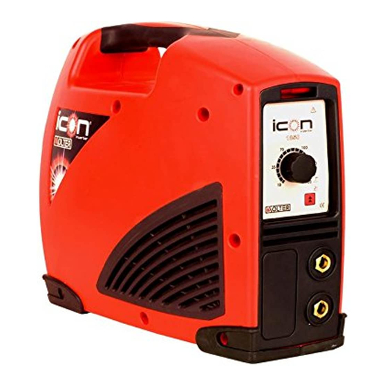
DESCRIPCIONES GENERALES El equipo de soldadura ICON con tecnología INVERTER SOLTER, consigue con una forma muy com- pacta y ligera una gran potencia y flexibilidad. Es posible aplicarlo de forma universal a cualquier tipo de soldadura de materiales tan diversos como aceros inoxidables, aceros aleados, aluminio (modelos ICON 2070 PRO DIGICEL ) u otros tipos de aceros, etc. -
Página 4: Ventilación
A/V Campo de regulación de la corriente y tensión de arco correspondiente. 10- datos correspondientes a la alimentación de la red. U1 Tensión de alimentación y tolerancia. I1eff Corriente eficaz absorbida. I1max Corriente máxima absorbida. 11- Nº de serie. Inverter ICON e ICON PRO SOLTER SOLDADURA S.L. -
Página 5: Descripción De Los Elementos Del Equipo
El diseño de la operativa con un solo mando está pensado para simplificar la modificación de los pará- metros. Usted no tiene que recordar complejas secuencias para entrar los datos, al contrario solo tiene que pulsar y girar el selector. Inverter ICON e ICON PRO SOLTER SOLDADURA S.L. - Página 6 En el caso de no tocar el mando durante unos segundos o si se ha iniciado la soldadura, el equipo automáticamente activa el parámetro I1 en modo modificación. En este caso, deberemos efectuar una pulsación corta para aceptar el dato del parámetro y poder seleccionar un nuevo parámetro. Inverter ICON e ICON PRO SOLTER SOLDADURA S.L.
- Página 7 Modo TIG ASD. Determina la sensibilidad para detectar la orden de apa- Sensibilidad gado del arco. El equipo iniciará el apagado del arco al separar el elec- trodo de la pieza, a mayor valor más alta será esta distancia. Inverter ICON e ICON PRO SOLTER SOLDADURA S.L.
- Página 8 Habilita la visualización del voltaje de soldadura durante el proceso de soldadura MMA Configura el límite de consumo del equipo en KVA. Los equipos SOLTER ICON con tecnología PFC, reducen automáticamente el amperaje máximo de soldadura para limitar el consumo en redes de alimentación dónde la tensión sea inferior a 190VAC.
-
Página 9: Modos De Soldadura
Los equipos SOLTER ICON con tecnología PFC son capaces de compensar las caídas de tensión que pudieran aparecer en la instalación como consecuencia del uso de una sección de cable defi- ciente. -
Página 10: Posibles Anomalías Y Soluciones
Se ha detectado un cortocircuito en la salida del equipo. Verifique que no tiene la pinza porta electro- dos en cortocircuito con la pinza de tierra. Si no es ningún cortocircuito externo, consultar con el servicio téc- nico. Inverter ICON e ICON PRO SOLTER SOLDADURA S.L. -
Página 11: Incidencias
Verificar la tensión de alimentación del equipo Indicador de ERROR iluminado. CAUSA SOLUCIÓN Esperar un tiempo para que se restablezca la temperatura El equipo está sobrecalentado de trabajo. La tensión de alimentación no es co- Verificar rrecta Inverter ICON e ICON PRO SOLTER SOLDADURA S.L. -
Página 12: Accesorios
MODELOS ICON 1850, ICON 1855 e ICON 1870 (A1) MODELOS ICON 2050 PRO, ICON 2055 PRO, ICON 2070 DIGICEL PRO e ICON 2060 PFC PRO (A2) ESQUEMA ELÉCTRICO ICON MMA (A3) ESQUEMA ELÉCTRICO ICON PRO MMA (A4) Inverter ICON e ICON PRO SOLTER SOLDADURA S.L. -
Página 13: Características Técnicas
IP23S Dimensiones (mm) 430x175x325 Peso (Kg) Fusible mínimo recomendado (A) ASISTENCIA TÉCNICA SOLTER ATENCIÓN AL CLIENTE 902 43 12 19 Email:solter@solter.com En caso de avería o consulta técnica, no dude en ponerse en contacto con nosotros y nuestro equipo de profesionales atenderá sus consultas de inmediato. -
Página 14: Safety And Protection
Only technically trained personnel can do this. Solter Soldadura denies all responsibility for negligent practices in the use or manipulation of this ma- chine. This manual must be kept with the equipment purchased. It is the responsibility of those per- sons who use and repair this machine to comply with the requirements of the above mentioned regulations. -
Página 15: General Descriptions
GENERAL DESCRIPTIONS ICON welding equipment with INVERTER SOLTER technology attains strength and flexibility with a com- pact, lightweight form. Universal application is possible to any type of welding materials - as diverse as stainless steel, alloyed steels, aluminum (ICON 2070 DIGICEL PRO) or other types of steel, etc. -
Página 16: Technical Data
6 minutes in operation and 4 minutes resting). A/V current regulation field and corresponding arc voltage. 10- Data corresponding to the mains supply. U1 Power voltage and tolerance. I1eff Efficient absorbed current. I1max Maximum absorbed current. 11- Serial N°. Inverter ICON e ICON PRO SOLTER SOLDADURA S.L. - Página 17 Single control concept Operational design with a single control has been created to simplify parameter modification. You no longer have to remember complex sequences for entering data, now just press and turn. Inverter ICON e ICON PRO SOLTER SOLDADURA S.L.
-
Página 18: Error Indication
If the control is not touched for several seconds or if welding has begun, the equipment will auto- matically activates the modification mode of I1 parameter. In this case, press for a short period to accept the parameter data and be able to select a new parameter. Inverter ICON e ICON PRO SOLTER SOLDADURA S.L. - Página 19 TIG ASD mode. Determines the sensitivity to detect the arc stoppage Sensitivity order. The equipment will begin to extinguish the arc on separating the electrode from the part; the higher the value the greater the distance. Inverter ICON e ICON PRO SOLTER SOLDADURA S.L.
- Página 20 MMA. Configure maxim input consumption level in KVA. SOLTER ICON equipments with PFC technology automatically reduced the maximum output welding current in order to prevent excessive consumption in AC power networks whose voltage is below 190Vac. The maximum welding input voltage is reduced gradually from 190 VAC to 85 VAC.
- Página 21 SOLTER ICON equipment featuring PFC technology is capable of offsetting voltage drops at the faci- lity that arising from the use of a section of faulty cable (the equipment can offset this drop and conti- nue operating as normal).
-
Página 22: Possible Problems And Solutions
In the event of a short circuit in the equipment output, check the electrode holder clamp is not in short circuit with the earth clamp. If an external short circuit is not the problem consult the technical department. Inverter ICON e ICON PRO SOLTER SOLDADURA S.L. - Página 23 The problem indicator is lit up and Er appears on the screen. CAUSE SOLUTION Wait for a time to ensure that the working temperature The equipment is overheating is re-established The electrical supply is not correct Check Inverter ICON e ICON PRO SOLTER SOLDADURA S.L.
- Página 24 Accessories which are compatible with the equipment must always be used with the equipment. Con- necting non-compatible or defective accessories may cause serious damage to the equipment. We re- commend the use of SOLTER original accessories. ASSEMBLY ICON 1850, ICON 1855 and ICON 1870 MODELS (A1)
-
Página 25: Technical Specifications
IP23S Dimensions (mm) 430x175x325 Weight (Kg) Minimum recommended fuse (A) SOLTER TECHNICAL ASSISTANCE CUSTOMER SERVICE 902 43 12 19 Email:solter@solter.com Please do not hesitate to contact us in the event of breakdown or technical difficulties. Our team of professionals will deal with your problem immediately. -
Página 26: Sécurité Et Protection
Lisez attentivement les indications de sécurité avant de mettre l’appareil en marche et de commencer les travaux de soudure. Les postes à souder SOLTER doivent être manipulées par des personnes for- mées ayant appris à utiliser les postes à souder et étant familiarisés avec les dispositifs de sécurité. -
Página 27: Descriptions Générales
DESCRIPTIONS GÉNÉRALES Le poste à souder ICON avec la technologie INVERTER SOLTER, est un poste très compact, léger, puissant et flexible. Vous pouvez l’utiliser de façon universelle pour tout type de soudage de matériaux aussi divers que les aciers inoxydables,aluminium (ICON 2070 DIGICEL PRO), les alliages d’acier ou d’autres types d’acier... -
Página 28: Déconnexion Automatique
A/V Intervalle de régulation du courant et tension d'arc correspondant. 10- Données correspondant à l'alimentation du réseau. U1 Tension d'alimentation et tolérance. I1eff Courant efficace absorbé. I1max I1max Courant maximal absorbé. 11- Nº de série. Inverter ICON e ICON PRO SOLTER SOLDADURA S.L. - Página 29 Le concept du fonctionnement à l’aide d’une seule commande a été conçu pour simplifier la modifica- tiondes paramètres. Vous n’avez plus à vous rappeler des séquences complexes pour saisir les données. Tout au contraire, vous n’avez plus qu’à appuyer ou qu’à tourner. Inverter ICON e ICON PRO SOLTER SOLDADURA S.L.
- Página 30 I1 en mode modification. Dans ce cas, il faudra appuyer brièvement sur le bouton pour accepter la donnée du paramètre et pouvoir sélectionner un nouveau paramètre. Inverter ICON e ICON PRO SOLTER SOLDADURA S.L.
-
Página 31: Paramètres
Mode TIG ASD. Elle correspond à la sensibilité pour détecter l'ordre d’extinction Sensibilité de l'arc. L'équipement commencera l'extinction de l'arc en éloignant l'électrode de la pièce. Plus grande sera la valeur et plus grande sera cette distance. Inverter ICON e ICON PRO SOLTER SOLDADURA S.L. - Página 32 Permet la visualisation du voltage de soudage pendant le processus de soudage MMA. Configure la limite de consommation de l'équipement en KVA. Les équipements SOLTER ICON avec technologie PFC, réduisent automatiquement l'ampérage maxi- mal de soudure pour limiter la consommation sur des réseaux d'alimentation où la tension est infé- rieure à...
-
Página 33: Modes De Soudage
10 et vous aurez la garantie que l'équipement ne pourra provoquer aucune surcharge. Les équipements SOLTER ICON disposant de la technologie PFC sont capables de compenser les chutes de tension qui pourraient apparaître dans l'installation suite à l'utilisation d'une section de câble déficiente. - Página 34 Il a été détecté un court-circuit à la sortie de l'équipement. Vérifiez que la pince porte-électrodes n’est pas en court-circuit avec la pince de terre. S’il n’y a aucun court-circuit externe, consulter le service techni- que. Inverter ICON e ICON PRO SOLTER SOLDADURA S.L.
- Página 35 L’indicateur d’erreur est allumé et l’indication Er s’affiche sur l’écran CAUSE SOLUTION L’appareil surchauffe Attendre un moment pour revenir à la température de travail. La tension d’alimentation n’est pas co- Vérifiez rrecte Inverter ICON e ICON PRO Inverter ICON e ICON PRO SOLTER SOLDADURA S.L. SOLTER SOLDADURA S.L.
- Página 36 En mode TIG ASD. L'arc s'éteint immédiatement après avoir été allumé. CAUSE SOLUTION Nous séparons trop l'électrode de la pièce au dé- Éloigner de 1 à 2 mm. marrage de l'arc. Nous avons une sensibilité très importante. Régler une plus faible sensibilité. Inverter ICON e ICON PRO SOLTER SOLDADURA S.L.
-
Página 37: Spécifications Techniques
ACCESSOIRES Vous devez toujours utiliser des accessoires compatibles avec l’appareil. La connexion d’accessoires non compatibles ou défectueux peut provoquer des pannes graves de l’appareil. Il est recommandé d’utiliser des accessoires originaux SOLTER. NOMENCLATURE MODÈLES ICON 1850, ICON 1855 et ICON 1870 (A1) MODÈLES... -
Página 38: Sicherheit Und Schutz
Produkt auch weiterhin den Anforderungen genannter Normen entspricht. Lesen Sie die Sicherheitshinweise gründlich bevor Sie das Gerät benutzen und mit den Schweißarbei- ten beginnen. Die Schweißgeräte von SOLTER dürfen nur von geschultem Personal verwendet werden, welches mit dem Arbeiten mit Schweißgeräten und den Sicherheitsvorkehrungen vertraut ist. -
Página 39: Allgemeine Beschreibungen
Sie bitte Ihre Sammelstelle für Elektromaterial. ALLGEMEINE BESCHREIBUNGEN Das Schweißgerät ICON mit der INVERTER SOLTER Technologie erzielt mit seiner sehr kompakten und leichten Form eine große Kraft und Flexibilität. Es ist universell für jegliche Schweißarbeit an den unterschiedlichsten Materialien wie rostfreier Stahl, gemischten Metallen, aluminium(ICON 2070 DIGICEL PRO) und anderen Metallarten anwendbar. -
Página 40: Automatisches Ausschalten
A/V Regulierungsbereich des Stromes und der Spannung des entsprechenden Schweißbogens. 10- Daten zur Speisung über das Netz. U1 : Speisespannung und Toleranz. I1eff : Verbrauchter Effektivstrom. I1max Maximal verbrauchter Strom. 11- Seriennummer. Inverter ICON e ICON PRO SOLTER SOLDADURA S.L. - Página 41 Der Entwurf der Handlung mit einer einzigen Steuerung ist dazu gedacht, um die Änderungen der Pa- rameter zu vereinfachen. Sie müssen sich nicht an die komplizierten Sequenzen erinnern, um die Daten einzugeben, im Gegenteil sie müssen nur drücken und drehen. Inverter ICON e ICON PRO SOLTER SOLDADURA S.L.
- Página 42 Gerät automatisch den Parameter I1 auf die Art Änderung akti- vieren. In diesem Fall, sollten wir ein kurzes drücken ausführen, um die Daten des Parameters zu akzeptieren und um einen neuen Parameter auswählen zu können. Inverter ICON e ICON PRO SOLTER SOLDADURA S.L.
- Página 43 Werkstück den Ausschaltbefehl des Bogens auszulösen. Das Gerät wird Empfindlich- beim trennen der Elektrode vom Werkstück den Ausschaltvorgang aktivieren. Die keit Distanz zwischen der Elektrode und dem Werkstück steigt mit dem Betrag des eingestellten Wertes. Inverter ICON e ICON PRO SOLTER SOLDADURA S.L.
- Página 44 Stellt die Grenze des Stromverbrauchs der Anlage in KVA ein. Die SOLTER ICON Anlagen mit PFC Technologie senken automatisch die maximale Schweißstroms- tärke, um den Verbrauch in den Anschlussnetzen zu senken, in denen die Spannung unter 190VAC beträgt. Die regulierbare maximale Schweißstromstärke wird allmählich auf 85VAC gesenkt.
- Página 45 Funktion Nr. 10 einzugeben. Auf diese Weise wird gewährleistet, dass das Gerät keine Überlastung erfährt. Die SOLTER ICON Anlagen mit PFC-Technologie sind in der Lage, die Spannungsabfälle, die in der Anlage aufgrund eines unzureichenden Querschnittes der Leiter auftreten könnten, zu kompensieren.
- Página 46 Error 5 Es wurde eine Fehlfunktion der Überwachungselektronik festgestellt. Es ist empfehlenswert, das Gerät während einigen Minuten auszuschalten und anschliessend wieder einzuschalten. Falls der Fehler Inverter ICON e ICON PRO Inverter ICON e ICON PRO SOLTER SOLDADURA S.L. SOLTER SOLDADURA S.L.
- Página 47 Anzeige auf dem Schirm. URSACHE LÖSUNG Sicherungen überprüfen oder den Schutz der Ausstattung. Es gibt keine Versorgungsspannung. Spannungüberprüfen. Netzkabel oder Steckdose sind defekt. Kontrollieren. Mögliche Überspannung des Netzes. Versorgungsspannung des Gerätes überprüfen. Inverter ICON e ICON PRO SOLTER SOLDADURA S.L.
- Página 48 MODELLE ICON 1850, ICON 1855 und ICON 1870 (A1) MODELLE ICON 2050 PRO, ICON 2055 PRO, ICON 2070 DIGICEL PRO und ICON 2060 PFC PRO (A2) ICON ELEKTRISCHES SCHEMA (A3) ICON PRO ELEKTRISCHES SCHEMA (A4). Inverter ICON e ICON PRO SOLTER SOLDADURA S.L.
- Página 49 IP23S Abmessungen (mm) 430x175x325 Gewicht (kg) Mindestsicherungen empfohlen (A) TECHNISCHER DIENST VON SOLTER KUNDENDIENST 902 43 12 19 Email:solter@solter.com Im Falle einer durch Sie nicht behebbaren Störung am Gerät oder wenn Sie technische Fragen haben, bitte kontaktieren Sie uns. Unsere professionellen Mitarbeiter werden Ihre Anragen so schnell wie möglich beantworten.
-
Página 50: Introdução
Ler com atenção as indicações de segurança antes decolocar em funcionamento o equipamento e iniciar os trabalhos de soldadura. Os equipamentos de soldadura SOLTER somente devem ser ma- nejados por pessoal formado e instruído na utilização de aparelhos de solda e familiarizado com as dis- posições de segurança.Pode encontrar informações detalhadas na publicação IEC ou CLC/TS 62081. - Página 51 DESCRIÇÕES GERAIS O equipamento de soldadura ICON com tecnologia INVERTER SOLTER, alcança, de forma bastante compacta e leve, uma grande potência e flexibilidade. É possível aplicar o mesmo de forma universal a qualquer tipo de soldadura de materiais tão diversos, como aço inoxidável, aço ligado, alumínio ( ICON 2070 DIGICEL PRO) ou outros tipos de aço, etc.
-
Página 52: Dados Técnicos
A/V Campo de regulação da corrente e respectiva tensão de arco. 10- Dados correspondentes à alimentação da rede. U1 U1 Tensão de alimentação e tolerância. I1eff Corrente eficaz absorvida. I1max Corrente máxima absorvida. 11- Nº de série. Inverter ICON e ICON PRO SOLTER SOLDADURA S.L. - Página 53 O desenho da operativa com apenas um comando está pensado para simplificar a modificação dos pa- râmetros. Não é necessário saber complexas sequências para entrar os dados, ao contrário é só pre- mire girar. Inverter ICON e ICON PRO SOLTER SOLDADURA S.L.
- Página 54 No caso de não tocar o comando durante alguns segundos ou quando iniciada a soldadura, o equipamento automaticamente activa o parâmetro I1 no modo modificação. Neste caso, premir de forma curta para aceitar o dado do parâmetro e poder seleccionar um novo parâmetro. Inverter ICON e ICON PRO SOLTER SOLDADURA S.L.
- Página 55 Modo TIG ASD. Determina a sensibilidade para detecção da ordem de apaga- mento do arco. O equipamento iniciará o apagamento do arco quando se afastar Sensibilidade o eléctrodo em relação à peça; quanto maior for o valor mais alta será esta dis- tância. Inverter ICON e ICON PRO SOLTER SOLDADURA S.L.
- Página 56 MMA. Configura o limite de consumo do equipamento em KVA. Os equipamentos SOLTER ICON com tecnologia PFC reduzem automaticamente a amperagem má- xima de soldadura para limitarem o consumo em redes de alimentação onde a tensão seja inferior a 190VAC. A amperagem máxima de soldadura regulável reduz-se paulatinamente até aos 85VAC.
-
Página 57: Modos De Soldagem
Os equipamentos SOLTER ICON com tecnologia PFC são capazes de compensar as quedas de ten- são que possam surgir na instalação em consequência do uso de uma secção de cabo deficiente. O equipamento pode compensar esta queda e continuar a trabalhar de forma habitual. -
Página 58: Possíveis Anomalias E Soluciones
Foi detectado um curto-circuito na saída do equipamento. Verifique se tem a pinça porta-eléctrodos em curto-circuito com a pinça de terra. Se não se tratar de nenhum curto-circuito externo, consultar o serviço técnico. Inverter ICON e ICON PRO SOLTER SOLDADURA S.L. - Página 59 O indicador de erro está iluminado e no ecrã aparece a indicação Er. CAUSA SOLUÇÃO O equipamento está com excesso de Aguardar algum tempo para que a temperatura de trabalho aquecimento. se restabeleça. A tensão de alimentação não é co- Revisar. rrecta. Inverter ICON e ICON PRO SOLTER SOLDADURA S.L.
-
Página 60: Acessórios
MODELOS ICON 1850, ICON 1855 e ICON 1870 (A1) MODELOS ICON 2050 PRO, ICON 2055 PRO, ICON 2070 DIGICEL PRO e ICON 2060 PFC PRO (A2) ESQUEMA ELÉCTRICO ICON (A3) ESQUEMA ELÉCTRICO ICON PRO (A4). Inverter ICON e ICON PRO SOLTER SOLDADURA S.L. -
Página 61: Especificações Técnicas
IP23S Dimensões (mm) 430x175x325 Peso (Kg) Fusível mínimo recomendado (A) ASSISTÊNCIA TÉCNICA SOLTER ATENDIMENTO AO CLIENTE 902 43 12 19 Email:solter@solter.com Em caso de avaria ou necessidade de consulta técnica, não hesite em entrar em contacto connosco e a nossa equipa de profissionais atenderá imediatamente as suas consultas. - Página 62 Inverter ICON e ICON PRO SOLTER SOLDADURA S.L.
- Página 63 Inverter ICON e ICON PRO SOLTER SOLDADURA S.L.
- Página 64 CERTIFICADO DE GARANTIA. (válido solo para España) Exija su cumplimentación al adquirir el aparato: SOLTER SOLDADURA S.L. garantiza a partir de la compra y durante 2 años, el artículo contra todo defecto de fabricación o de materiales. En caso de avería, la garantía cubre las piezas de recambio y la mano de obra, y el titular del equipo disfrutará...