Tabla de contenido
Publicidad
Idiomas disponibles
Idiomas disponibles
Enlaces rápidos
Harbor Breeze® is a registered trademark
of LF, LLC. All Rights Reserved.
ATTACH YOUR RECEIPT HERE
Serial Number
Questions, problems, missing parts? Before returning to your retailer, call our customer
service department at
5 p.m., EST, Friday.
EB15408
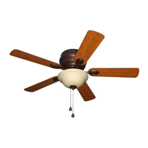
MAYFIELD CEILING FAN
Purchase Date
1-800-643-0067, 8 a.m. - 6 p.m., EST, Monday - Thursday, 8 a.m. -
1
ITEM
#0331094
MODEL
#BTH44ABZC5C
BTH44BNK5C
BTH44WW5C
Español p. 20
Lowes.com/harborbreeze
0331096
0648636
4009654
Publicidad
Capítulos
Tabla de contenido
Solución de problemas

Manuales relacionados para Harbor Breeze MAYFIELD BTH44ABZC5C


Resumen de contenidos para Harbor Breeze MAYFIELD BTH44ABZC5C
- Página 1 ITEM #0331094 0331096 0648636 MAYFIELD CEILING FAN MODEL #BTH44ABZC5C Harbor Breeze® is a registered trademark BTH44BNK5C of LF, LLC. All Rights Reserved. BTH44WW5C Español p. 20 ATTACH YOUR RECEIPT HERE 4009654 Serial Number Purchase Date Questions, problems, missing parts? Before returning to your retailer, call our customer service department at 1-800-643-0067, 8 a.m.
-
Página 2: Tabla De Contenido
TABLE OF CONTENTS Safety Information .......................2 Package Contents .......................4 Hardware Contents ..........................5 Preparation ..........................5 Initial Installation ........................6 Wiring ..........................8 Final Installation ........................10 Operating Instructions .......................15 Care and Maintenance ......................16 Troubleshooting .........................17 Limited Lifetime Warranty ....................18 Replacement Parts List .....................19 SAFETY INFORMATION READ AND SAVE THESE INSTRUCTIONS Please read and understand this entire manual before attempting to assemble, install or operate the product. - Página 3 SAFETY INFORMATION DANGER When using an existing outlet box, make sure the outlet box is securely attached to the building structure and can support the full weight of the fan. Failure to do this can result in serious injury or death.
-
Página 4: Package Contents
PACKAGE CONTENTS PART DESCRIPTION PART DESCRIPTION QUANTITY QUANTITY Motor Housing 5.4 mm Lock Washer (preassembled) + 1 extra Mounting Bracket Hex Nut (preassembled) Motor Assembly Lock Washer Light Kit Fitter (preassembled) Glass Shade Rubber Washer Pull Chain Extension (preassembled) Blade Motor Housing Mounting Finial Plate Screw (preassembled) -
Página 5: Hardware Contents
HARDWARE CONTENTS (shown actual size) Blade Fiber Screw Blade E3 Wire Washer Connector Qty. 15 + 1 extra Qty. 15 Qty. 4 + 1 extra PREPARATION Before beginning assembly of product, make sure all parts are present. Compare parts with package contents list and hardware contents list. -
Página 6: Initial Installation
INITIAL INSTALLATION Turn off circuit breakers and wall switch to the fan supply line leads. DANGER: Failure to disconnect power supply prior to installation may result in serious injury or death. This fan can be mounted as a flushmount on a regular (no-slope) ceiling only. -
Página 7: Important
INITIAL INSTALLATION Secure mounting bracket (B) to outlet box using screws, spring washers and flat washers provided with the outlet box. *NOTE: It is very important you use the proper hardware when installing the mounting bracket (B) as this will support the fan. Remove motor screws (M) and 5.4 mm lock washers (N) from underside of motor and save for blade arm (J) attachment later on. -
Página 8: Wiring
WIRING WARNING: To reduce the risk of fire, electrical shock or personal injury, wire connectors provided with this fan are designed to accept only one 12-gauge house wire and two lead wires from the fan. If your house wire is larger than 12-gauge or there is more than one house wire to connect to the corresponding fan lead wires, consult an electrician for the proper size wire connectors to use. - Página 9 WIRING 1c. FAN AND LIGHT CONTROLLED BY TWO FAN AND LIGHT CONTROLLED BY TWO WALL SWITCHES FAN AND LIGHT CONTROLLED BY TWO WALL SWITCHES WALL SWITCHES: If you intend to control the fan BLACK (WALL SWITCH FOR LIGHT) and light with separate wall switches, connect BLACK (WALL SWITCH) BLACK wire from fan to BLACK wire from the 120 V Power...
-
Página 10: Final Installation
FINAL INSTALLATION 1. Remove motor assembly (C) from "J" hook. Align holes in motor assembly (C) with holes in mounting bracket (B). Secure motor assembly (C) with mounting bracket flat washers (S) and mounting bracket nuts (U) previously removed (Step 3, page 6). 2. - Página 11 FINAL INSTALLATION Locate motor screws (M) and 5.4 mm lock washers (N) previously removed (Step 5, page 7). Insert two motor screws (M), along with 5.4 mm lock washers (N), through one blade arm (J) to attach blade arm (J) to motor. Tighten motor screws (M) securely.
- Página 12 FINAL INSTALLATION To attach light kit fitter (D) to motor assembly (C), align holes in switch housing cap, at top of light kit fitter (D), with holes in switch housing. (Make Switch sure to align gap on top edge of the switch Housing housing cap with the reverse switch on switch housing for the correct fit.) Re-insert switch...
- Página 13 FINAL INSTALLATION Locate rubber washer (Q), finial plate (H), and finial (I) that were previously removed (Step 5, page 11). Place rubber washer (Q) inside glass shade (E) over center hole. Align hole in center of glass shade (E) with threaded rod on light kit fitter (D), allowing pull chains to come through corresponding holes in glass shade (E).
- Página 14 FINAL INSTALLATION If you do NOT wish to use the light kit, remove the hex nut (O) and lock washer (P) WHITE BLACK from the threaded rod at the top of the light kit fitter (D). Unscrew the switch housing cap to remove it from the light kit fitter (D), and then gently feed the BLACK and WHITE wires from the light kit fitter (D) through the hole in the...
-
Página 15: Operating Instructions
OPERATING INSTRUCTIONS The pull chain located on the switch housing Switch has four positions to control fan speed. One pull Housing is HIGH, two is MEDIUM, three is LOW and four turns the fan OFF. The pull chain located in the center is used to turn the light ON or OFF. -
Página 16: Care And Maintenance
OPERATING INSTRUCTIONS 3a. In warmer weather, setting the reverse switch in the DOWN position will result in downward airflow creating a wind chill effect. 3b. In cooler weather, setting the reverse switch in the UP position will result in upward airflow that can help move stagnant, hot air off the ceiling area. -
Página 17: Troubleshooting
TROUBLESHOOTING WARNING: Before beginning work, shut off the power supply to avoid electrical shock. PROBLEM POSSIBLE CAUSE CORRECTIVE ACTION Fan does not 1. Reverse switch not engaged. 1. Push switch firmly either up or move. down. 2. Power is off or fuse is blown. 2. -
Página 18: Limited Lifetime Warranty
LIMITED LIFETIME WARRANTY The distributor warrants this fan to be free from defects in workmanship and materials present at time of shipment from the factory for Lifetime limited from the date of purchase. This warranty applies only to the original purchaser. The distributor agrees to correct any defect at no charge or, at our option, replace the ceiling fan with a comparable or superior model. -
Página 19: Replacement Parts List
PART # PART # Mounting Bracket 0331094-B 0331096-A 0648636-A Light Kit Fitter 0331094-D 0331096-B 0648636-B Blade 0331094-G 0331096-D 0648636-D Blade Arm 0331094-J 0331096-G 0648636-G Printed in China Harbor Breeze® is a registered trademark of LF, LLC. All Rights Reserved. Lowes.com/harborbreeze JMLI1508... -
Página 20: Adjunte Su Recibo Aquí
ARTÍCULO # 0331094 0331096 0648636 VENTILADOR DE TECHO MAYFIELD Harbor Breeze ® es una marca registrada de LF, LLC. Todos los derechos reservados. MODELO # BTH44ABZC5C BTH44BNK5C BTH44WW5C ADJUNTE SU RECIBO AQUÍ 4009654 Número de serie Fecha de compra ¿Preguntas, problemas, piezas faltantes? Antes de volver a la tienda, llame a nuestro Departamento de Servicio al Cliente al 1-800-643-0067, de lunes a jueves de 8 a.m. - Página 21 ÍNDICE Información de seguridad ....................21 Contenido del paquete ......................23 Aditamentos ........................24 Preparación ........................24 Instalación inicial .......................25 Cableado ...........................27 Instalación final .........................29 Instrucciones de funcionamiento ..................34 Cuidado y mantenimiento ....................35 Solución de problemas .....................36 Garantía limitada de por vida ...................37 Lista de piezas de repuesto ....................38 INFORMACIÓN DE SEGURIDAD LEA Y GUARDE ESTAS INSTRUCCIONES Lea y comprenda completamente este manual antes de intentar ensamblar, instalar o usar el producto.
-
Página 22: Información De Seguridad
INFORMACIÓN DE SEGURIDAD PELIGRO Si utiliza una caja de salida existente, asegúrese de que esté bien sujeta a la estructura del edificio y que pueda sostener el peso del ventilador. El incumplimiento de dicho paso podría provocar lesiones graves o la muerte. La estabilidad de la caja de salida es fundamental para minimizar el tambaleo y el ruido en el ventilador una vez que la instalación esté... -
Página 23: Contenido Del Paquete
CONTENIDO DEL PAQUETE PIEZA DESCRIPCIÓN PIEZA DESCRIPCIÓN CANTIDAD CANTIDAD Carcasa del motor Arandela de seguridad de 5,4 mm (preensamblada) + 1 adicional Soporte de montaje Tuerca hexagonal Ensamblaje del motor (preensamblada) Soporte del kit de iluminación Arandela de seguridad Pantalla de vidrio (preensamblada) Extensión para la cadena de tiro Arandela de goma... -
Página 24: Aditamentos
ADITAMENTOS (se muestran en tamaño real) Tornillo Arandela para para aspa aspa de fibra Conector de cables E3 Cant. 15 Cant. 15 + 1 adicional + 1 adicional Cant. 4 PREPARACIÓN Antes de comenzar a ensamblar el producto, asegúrese de tener todas las piezas. Compare las piezas con la lista del contenido del paquete y la lista de aditamentos. -
Página 25: Instalación Inicial
INSTALACIÓN INICIAL Interrumpa el suministro de energía del ventilador colocando los interruptores de circuito y el interruptor de pared en la posición de apagado. PELIGRO: Si no desconecta el suministro de electricidad antes de la instalación, pueden producirse lesiones graves o la muerte. Este ventilador se puede montar al ras en un techo regular (sin inclinación) solamente. - Página 26 INSTALACIÓN INICIAL Asegure el soporte de montaje (B) a la caja de salida con los tornillos, las arandelas de resorte y las arandelas planas provistos con la caja de salida. *NOTA: Es muy importante usar los artículos de ferretería correctos al instalar el soporte de montaje (B) puesto que sirve para sostener el ventilador.
-
Página 27: Cableado
CABLEADO ADVERTENCIA: Para reducir el riesgo de incendios, descargas eléctricas o lesiones personales, los conectores de cables proporcionados con este ventilador están diseñados para aceptar solo un conductor de la casa de calibre 12 y dos cables conductores del ventilador. Si el conductor de la casa es de un calibre superior a 12 o hay más de un conductor de la casa para conectar a los cables conductores del ventilador correspondientes, consulte a un electricista cuál es el tamaño adecuado de los conectores de cables que debe utilizar. -
Página 28: Dos Interruptores De Pared
CABLEADO 1c. VENTILADOR Y LUZ CONTROLADOS POR VENTILADOR Y LUZ CONTROLADOS POR DOS INTERRUPTORES DE PARED FAN AND LIGHT CONTROLLED BY TWO WALL SWITCHES DOS INTERRUPTORES DE PARED: Si desea NEGRO (INTERRUPTOR DE PARED) controlar el ventilador y la luz con interruptores de pared independientes, conecte el conductor Alimentación NEGRO (INTERRUPTOR DE PARED) -
Página 29: Instalación Final
CABLEADO IMPORTANTE: Si usa un regulador de intensidad de rango completo (no se incluye) para controlar la velocidad del ventilador, provocará un zumbido intenso del ventilador. Para reducir el riesgo de incendios o descargas eléctricas, NO use un regulador de intensidad de rango completo para controlar la velocidad del ventilador. - Página 30 INSTALACIÓN FINAL 3. Inserte parcialmente tres tornillos para aspa (AA) junto con tres arandelas para aspa de fibra (BB) en los orificios del aspa (G) para fijar el brazo de aspa (J) al aspa (G). Luego, apriete cada uno de los tornillos para aspa (AA), comenzando por el que está...
- Página 31 INSTALACIÓN FINAL Ubique los conductores AZUL (o NEGRO) y BLANCO de la carcasa del interruptor etiquetados FOR LIGHT (PARA EL KIT DE ILUMINACIÓN) y retire el plástico que mantiene unidos a estos dos conductores. Retire también las tapas de Carcasa del seguridad molex desde la parte inferior de los interruptor Conexiones...
- Página 32 INSTALACIÓN FINAL Ubique la arandela de goma (Q), la placa del remate (H) y el remate (I) que retiró previamente (Paso 5, página 30). Coloque la arandela de goma (Q) dentro de la pantalla vidrio (E), sobre el orificio central. Alinee el orificio central de la pantalla de vidrio (E) con la varilla roscada en el soporte del kit de iluminación (D), pasando las cadenas de tiro por los orificios correspondientes en la pantalla de...
- Página 33 INSTALACIÓN FINAL Si NO desea usar el kit de iluminación, retire la tuerca hexagonal (O) y la arandela de BLANCO seguridad (P) de la varilla roscada de la parte NEGRO superior del soporte del kit de iluminación (D). Desenrosque la tapa de la carcasa del interruptor para retirarla del soporte del kit de iluminación (D), y luego pase con cuidado los conductores NEGRO y BLANCO del soporte del...
-
Página 34: Instrucciones De Funcionamiento
INSTRUCCIONES DE FUNCIONAMIENTO La cadena de tiro ubicada en la carcasa del Carcasa del interruptor tiene cuatro posiciones para interruptor controlar la velocidad del ventilador. Jale una vez para la posición HIGH (ALTA), dos para la posición MEDIUM (MEDIA), tres para la posición LOW (BAJA) y cuatro para la posición OFF (APAGADO) que apaga el ventilador. -
Página 35: Cuidado Y Mantenimiento
INSTRUCCIONES DE FUNCIONAMIENTO 3a. En climas más cálidos, la configuración del interruptor de reversa en la posición DOWN (HACIA ABAJO) creará un flujo de aire descendente que generará un efecto de viento refrescante. 3b. En climas más fríos, la configuración del interruptor de reversa en la posición UP (HACIA ARRIBA) creará... -
Página 36: Solución De Problemas
SOLUCIÓN DE PROBLEMAS ADVERTENCIA: Antes de comenzar cualquier trabajo, desconecte el suministro de electricidad para evitar descargas eléctricas. PROBLEMA CAUSA POSIBLE ACCIÓN CORRECTIVA El ventilador 1. El interruptor de reversa no 1. Mueva firmemente el interruptor hacia no se mueve. está... -
Página 37: Garantía Limitada De Por Vida
GARANTÍA LIMITADA DE POR VIDA El distribuidor garantiza que este ventilador no presentará defectos en la mano de obra ni en los materiales presentes al momento del transporte desde la fábrica durante un período limitado de por vida a partir de la fecha de compra. Esta garantía es válida solo para el comprador original. El distribuidor acepta reparar cualquier defecto sin cargo o, según nuestro criterio, remplazar el ventilador de techo por un modelo comparable o superior. -
Página 38: Lista De Piezas De Repuesto
0331094-B 0331096-B 0648636-B Soporte del kit de 0331094-D 0331096-D 0648636-D iluminación Aspa 0331096-G 0648636-G 0331094-G Brazo de aspa 0331096-J 0648636-J 0331094-J Impreso en China ® Harbor Breeze es una marca registrada de LF, LLC. Todos los derechos reservados. Lowes.com/harborbreeze JMLI1508...