Tabla de contenido
Publicidad
Idiomas disponibles
Idiomas disponibles
Enlaces rápidos
Harbor Breeze® is a registered trademark
of LF, LLC. All Rights Reserved.
Purchase Date
Questions, problems, missing parts? Before returning to your retailer, call our customer
service department at 1-800-643-0067, 8 a.m. - 8 p.m., EST, Monday - Sunday.
BM19336
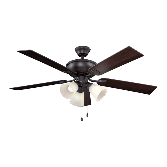
Sailor Bay Ceiling Fan
1
ITEM #1461040
1461041
1461042
MODEL #RLG52NWZ5L
RLG52BNK5L
RLG52WW5L
Español p. 21
ATTACH YOUR RECEIPT HERE
ADJUNTE SU RECIBO AQUÍ
4007498
Publicidad
Capítulos
Tabla de contenido
Solución de problemas

Manuales relacionados para Harbor Breeze RLG52NWZ5L


Resumen de contenidos para Harbor Breeze RLG52NWZ5L
- Página 1 ITEM #1461040 1461041 1461042 Sailor Bay Ceiling Fan MODEL #RLG52NWZ5L Harbor Breeze® is a registered trademark RLG52BNK5L of LF, LLC. All Rights Reserved. RLG52WW5L Español p. 21 ATTACH YOUR RECEIPT HERE ADJUNTE SU RECIBO AQUÍ 4007498 Purchase Date Questions, problems, missing parts? Before returning to your retailer, call our customer service department at 1-800-643-0067, 8 a.m.
-
Página 2: Tabla De Contenido
TABLE OF CONTENTS Safety Information ........................2 Package Contents ........................5 Hardware Contents .......................6 Preparation ...........................6 Initial Installation ........................6 Downrod-Style Fan Mounting ....................8 Closemount-Style Fan Mounting ..................10 Wiring ..........................12 Final Installation ........................14 Operating Instructions .......................16 Care and Maintenance ......................18 Troubleshooting........................18 Limited Lifetime Warranty ....................19 Replacement Parts List ......................20 SAFETY INFORMATION READ AND SAVE THESE INSTRUCTIONS... - Página 3 SAFETY INFORMATION DANGER When using an existing outlet box, make sure the outlet box is securely attached to the building structure and can support the full weight of the fan. Failure to do this can result in serious injury or death.
- Página 4 SAFETY INFORMATION CAUTION Modifications not approved by the party responsible for compliance could void the user's authority to operate the equipment. *NOTE: This equipment has been tested and found to comply with the limits for a Class B digital device, pursuant to Part 15 of the FCC Rules. These limits are designed to provide reasonable protection against harmful interference in a residential installation.
-
Página 5: Package Contents
PACKAGE CONTENTS PART DESCRIPTION PART DESCRIPTION QUANTITY QUANTITY Lock Washer Downrod (preassembled) + 1 extra Canopy Pin (preassembled) Mounting Bracket Clip (preassembled) Motor Housing Bulb Star Washer Canopy Mounting Screw (preassembled) (preassembled) Light Kit Fitter Switch Housing Screw Blade (preassembled) Blade Arm Glass Shade Motor Screw... -
Página 6: Hardware Contents
HARDWARE CONTENTS (shown actual size) Blade Blade Wire Screw Washer Connector Qty. 15 Qty. 15 Qty. 4 + 1 extra + 1 extra Pull Chain Extension Qty. 2 PREPARATION Before beginning assembly of product, make sure all parts are present. Place motor on carpet or on foam to avoid damage to finish. -
Página 7: Important
INITIAL INSTALLATION 2. Determine mounting method to use. A. Downrod mount (standard or angled ceiling) B. Closemount (standard ceiling only) 19° max. IMPORTANT: If using the angle mount, ensure the ceiling angle is not steeper than 19°. *Helpful Hint: Downrod-style mounting is best suited for ceilings 8 ft. -
Página 8: Downrod-Style Fan Mounting
INITIAL INSTALLATION 5. Remove preassembled motor screws (J) and lock washers (K) from underside of motor housing (D). If there are plastic motor blocks installed with the motor screws (J), discard the plastic motor blocks. Note: Make sure to keep loose hardware separate to avoid confusion during installation. - Página 9 DOWNROD-STYLE FAN MOUNTING Slip downrod (A) into motor housing yoke, align holes and re-install pin (L) and clip (M). Tighten set screws in motor housing yoke and then tighten preassembled nuts on the set screws. Set Screw & Nut Yoke Depending on the length of downrod you use, you may need to cut the lead wires back to simplify the wiring.
-
Página 10: Closemount-Style Fan Mounting
DOWNROD-STYLE FAN MOUNTING Install hanging ball of downrod (A) into opening of mounting bracket (C). Align one of the slots in hanging ball with tab in mounting bracket (C). DANGER: Failure to align one of the slots in the ball with the tab may result in serious injury or death. - Página 11 CLOSEMOUNT-STYLE FAN MOUNTNG Pull wires up through hole in the middle of the Screw canopy (B) and attach canopy (B) to motor housing (D) using the three previously removed Lock screws and lock washers. Washer Temporarily hang fan on the tab on the mounting bracket (C) using one of the non-slotted holes in the canopy (B).
-
Página 12: Wiring
WIRING WARNING: To reduce the risk of fire, electrical shock or personal injury, wire connectors provided with this fan are designed to accept only one 12-gauge house wire and two lead wires from the fan. If your house wire is larger than 12-gauge or there is more than one house wire to connect to the corresponding fan lead wires, consult an electrician for the proper size wire connectors to use. - Página 13 WIRING 1b. FAN CONTROLLED BY PULL CHAIN, LIGHT FAN CONTROLLED BY PULL CHAIN, LIGHT BY WALL SWITCH FAN AND LIGHT CONTROLLED BY TWO WALL SWITCHES BY WALL SWITCH: Connect BLACK wire from fan to BLACK wire from ceiling. Connect BLUE wire from fan to the BLACK (or RED) wire from the 120V POWER FROM CEILING...
-
Página 14: Final Installation
FINAL INSTALLATION 1. Temporarily lift canopy (B) to mounting bracket (C) to determine which two canopy mounting screws (O) in mounting bracket (C) align with slotted holes in canopy (B) and partially loosen these two canopy mounting screws (O). Remove the other two canopy mounting screws (O) along with star washers (E). - Página 15 FINAL INSTALLATION Remove the three preassembled switch housing screws (P) from light kit fitter (F). Locate the BLACK (or BLUE) and WHITE wires in the switch housing preassembled on motor housing (D) that are labeled FOR LIGHT KIT CONNECTION and remove plastic from these two wires. Switch BLACK (or BLUE) WHITE...
-
Página 16: Operating Instructions
FINAL INSTALLATION Install bulbs (N). IMPORTANT: When you need to replace bulbs, please allow the bulb(s) and glass shade(s) to cool down before touching them. 8. Attach pull chain extensions (DD) or custom pull chain extensions (not included) to corresponding fan and light pull chains. - Página 17 OPERATING INSTRUCTIONS 2. The light pull chain, located in the middle, is used to turn the lights ON or OFF. 3. Use the fan reverse switch, located on the Reverse Switch switch housing, to optimize your fan for seasonal performance. A ceiling fan will allow you to raise your thermostat setting in summer and lower your thermostat setting in winter without feeling a difference in your comfort.
-
Página 18: Care And Maintenance
OPERATING INSTRUCTIONS 3C. IMPORTANT: Reverse switch must be set either completely UP or completely DOWN for fan to function. If the reverse switch is set in the middle position, fan will not operate. CARE AND MAINTENANCE At least twice each year, lower canopy (B) to check downrod (A) assembly, and then tighten all screws on the fan. -
Página 19: Limited Lifetime Warranty
TROUBLESHOOTING PROBLEM POSSIBLE CAUSE CORRECTIVE ACTION Excessive wobbling. 1. Blades are loose. 1. Tighten all blade screws. 2. Blade arms incorrectly attached. 2. Re-install blade arms. 3. Unbalanced blades. 3. Switch one blade with a blade from the opposite side. 4. -
Página 20: Replacement Parts List
REPLACEMENT PARTS LIST For replacement parts, call our customer service department at 1-800-643-0067, 8 a.m. - 8 p.m., EST, Monday - Sunday. #1461040 #1461041 #1461042 PART DESCRIPTION PART # PART # PART # Downrod 1461040-A 1461041-A 1461042-A Canopy 1461040-B 1461041-B 1461042-B Mounting Bracket 1461040-C... - Página 21 Ventilador de techo Sailor Bay Harbor Breeze es una marca registrada ® de LF, LLC. Todos los derechos reservados. MODELO #RLG52NWZ5L RLG52BNK5L RLG52WW5L 4007498 Fecha de compra ¿Preguntas, problemas, piezas faltantes? Antes de volver a la tienda, llame a nuestro Departamento de Servicio al Cliente al 1-800-643-0067, de lunes a domingo de 8 a.m.
- Página 22 ÍNDICE Información de seguridad ....................22 Contenido del paquete .......................25 Aditamentos ........................26 Preparación ........................26 Instalación inicial ........................26 Montaje del ventilador en estilo de varilla ................28 Montaje del ventilador en estilo cerrado ................30 Cableado ..........................32 Instalación final ........................34 Instrucciones de funcionamiento ..................36 Cuidado y mantenimiento ....................38 Solución de problemas .......................38 Garantía limitada de por vida .....................39...
-
Página 23: Información De Seguridad
INFORMACIÓN DE SEGURIDAD PELIGRO Si utiliza una caja de salida existente, asegúrese de que esté bien sujeta a la estructura del edificio y que pueda sostener el peso del ventilador. El incumplimiento de dicho paso podría provocar lesiones graves o la muerte. La estabilidad de la caja de salida es fundamental para minimizar el balanceo y el ruido en el ventilador una vez que la instalación esté... - Página 24 INFORMACIÓN DE SEGURIDAD PRECAUCIÓN Las modificaciones que no estén aprobadas por la parte responsable del cumplimiento podrían anular la autorización del usuario para utilizar el equipo. *NOTA: este equipo ha sido probado y se ha verificado que cumple con los límites para un dispositivo digital clase B, conforme a la sección 15 de las reglas de la FCC.
-
Página 25: Contenido Del Paquete
CONTENIDO DEL PAQUETE PIEZA DESCRIPCIÓN PIEZA DESCRIPCIÓN CANTIDAD CANTIDAD Arandela de seguridad Varilla (preensamblada) + 1 adicional Base Pasador (preensamblado) Soporte de montaje Sujetador (preensamblado) Carcasa del motor Bombilla Arandela de estrella Tornillo de montaje de (preensamblada) la base (preensamblado) Soporte del kit de iluminación Tornillo de la carcasa del Aspa... -
Página 26: Aditamentos
ADITAMENTOS (se muestran en tamaño real) Arandela Tornillo Conector de para aspa para aspa cables Cant. 15 Cant. 15 Cant. 4 + 1 adicional + 1 adicional Extensión para la cadena de tiro Cant. 2 PREPARACIÓN Antes de comenzar a ensamblar el producto, asegúrese de tener todas las piezas. Ubique el motor sobre una alfombra o espuma para evitar dañar el acabado. -
Página 27: Importante
INSTALACIÓN INICIAL 2. Determine el método de montaje que utilizará. A. Montaje de varilla (techos estándares o en ángulo) 19° máx. B. Montaje cerrado (sólo para techos estándares) IMPORTANTE: si utiliza el montaje en ángulo, verifique que el ángulo del techo no tenga una inclinación superior a los 19°. -
Página 28: Montaje Del Ventilador En Estilo De Varilla
INSTALACIÓN INICIAL 5. Retire los tornillos del motor (J) y las arandelas de seguridad (K) preensamblados de la parte inferior de la carcasa del motor (D). Si hay topes plásticos del motor instalados con los tornillos del motor (J), deseche los topes plásticos del motor. Nota: asegúrese de mantener todo el aditamento Tope separado para evitar confundirlo durante la... - Página 29 MONTAJE DEL VENTILADOR EN ESTILO DE VARILLA Deslice la varilla (A) en la horquilla de la carcasa del motor, alinee los orificios y vuelva a instalar el pasador (L) y el sujetador (M). Apriete los tornillos de fijación en la horquilla de la carcasa del motor y apriete las tuercas previamente ensambladas a los tornillos de fijación.
-
Página 30: Montaje Del Ventilador En Estilo Cerrado
MONTAJE DEL VENTILADOR EN ESTILO DE VARILLA Instale la bola para colgar en la varilla (A) en la abertura del soporte de montaje (C). Alinee una de las ranuras en la bola para colgar con la lengüeta del soporte de montaje (C). PELIGRO: si no alinea una de las ranuras de la bola con la lengüeta, pueden producirse lesiones graves o la muerte. - Página 31 MONTAJE DEL VENTILADOR EN ESTILO CERRADO Pase los cables hacia arriba a través del orificio en el centro de la base (B) y fije la base (B) a la Tornillo carcasa del motor (D) con los tres tornillos y las Arandela de tres arandelas de seguridad que retiró...
-
Página 32: Cableado
CABLEADO ADVERTENCIA: para reducir el riesgo de incendios, descargas eléctricas o lesiones personales, los conectores de cables incluidos con este ventilador están diseñados para soportar solo un cable de la casa de calibre 12 y dos cables conductores del ventilador. Si el cable de la casa es de un calibre superior a 12 o hay más de un cable para conectar a los cables conductores del ventilador correspondientes, consulte a un... -
Página 33: Cadena De Tiro Y Luz Controlada Por Interruptor De Pared
CABLEADO 1b. VENTILADOR CONTROLADO POR VENTILADOR CONTROLADO POR CADENA DE TIRO Y LUZ CONTROLADA POR INTERRUPTOR DE PARED CADENA DE TIRO Y LUZ CONTROLADA POR INTERRUPTOR DE PARED: conecte el cable NEGRO del ventilador al cable NEGRO del techo. ALIMENTACIÓN Conecte el cable AZUL del ventilador al cable DE 120 V DESDE EL TECHO... -
Página 34: Instalación Final
INSTALACIÓN FINAL 1. Levante temporalmente la base (B) hacia el soporte de montaje (C) para determinar cuáles son los dos Opción de montaje tornillos de montaje de la base (O) en el soporte de Opción de cerrado varilla montaje (C) que se alinean con los orificios ranurados en la base (B) y afloje parcialmente estos dos tornillos de montaje de la base (O). - Página 35 INSTALACIÓN FINAL Retire los tres tornillos de la carcasa del interruptor (P) preensamblados del soporte del kit de iluminación (F). Ubique los cables NEGRO (o AZUL) y BLANCO, etiquetados como FOR LIGHT KIT CONNECTION (PARA ENCHUFE DEL JUEGO DE LUZ), en la carcasa del interruptor que se encuentra preensamblada en la carcasa del motor (D) y retire el plástico de estos dos cables.
-
Página 36: Instrucciones De Funcionamiento
INSTALACIÓN FINAL Instale las bombillas (N). IMPORTANTE: cuando necesite reemplazar las bombillas, deje que estas y las pantallas de vidrio se enfríen antes de tocarlas. 8. Conecte las extensiones para la cadena de tiro (DD) o las extensiones para la cadena de tiro personalizadas (no incluidas) con las cadenas de tiro del ventilador y luz correspondientes. - Página 37 INSTRUCCIONES DE FUNCIONAMIENTO 2. La cadena de tiro de iluminación, ubicada en la parte central, se utiliza para ENCENDER o APAGAR las luces. 3. Utilice el interruptor de reversa del ventilador, Interruptor ubicado en la carcasa del interruptor, para de reversa optimizar el rendimiento de su ventilador según la Carcasa del estación del año.
-
Página 38: Cuidado Y Mantenimiento
INSTRUCCIONES DE FUNCIONAMIENTO 3C. IMPORTANTE: el interruptor de reversa se debe configurar ya sea completamente UP (arriba) o completamente DOWN (abajo) para que funcione el ventilador. Si el interruptor de reversa se configura en la posición del medio, el ventilador no funcionará. CUIDADO Y MANTENIMIENTO Al menos dos veces al año, baje la base (B) para revisar el ensamble de la varilla (A) y luego apriete todos los tornillos en el ventilador. -
Página 39: Garantía Limitada De Por Vida
SOLUCIÓN DE PROBLEMAS PROBLEMA CAUSA POSIBLE ACCIÓN CORRECTIVA Hay un tambaleo 1. Apriete todos los tornillos de las aspas. 1. Las aspas están flojas. excesivo. 2. Los brazos de las aspas no están 2. Vuelva a instalar los brazos de las aspas. ajustados correctamente. -
Página 40: Lista De Piezas De Repuesto
LISTA DE PIEZAS DE REPUESTO Para obtener piezas de repuesto, llame a nuestro Departamento de Servicio al Cliente al 1-800-643-0067, de lunes a domingo de 8 a.m. a 8 p.m., hora estándar del Este. #1461040 #1461041 #1461042 PIEZA DESCRIPCIÓN PIEZA # PIEZA # PIEZA # Varilla...